EP2146114A2 - Teleskop-Doppelspindelantrieb - Google Patents
Teleskop-Doppelspindelantrieb Download PDFInfo
- Publication number
- EP2146114A2 EP2146114A2 EP09009298A EP09009298A EP2146114A2 EP 2146114 A2 EP2146114 A2 EP 2146114A2 EP 09009298 A EP09009298 A EP 09009298A EP 09009298 A EP09009298 A EP 09009298A EP 2146114 A2 EP2146114 A2 EP 2146114A2
- Authority
- EP
- European Patent Office
- Prior art keywords
- thread
- spindle
- linear drive
- nut
- coupling element
- Prior art date
- Legal status (The legal status is an assumption and is not a legal conclusion. Google has not performed a legal analysis and makes no representation as to the accuracy of the status listed.)
- Granted
Links
Images


Classifications
-
- F—MECHANICAL ENGINEERING; LIGHTING; HEATING; WEAPONS; BLASTING
- F16—ENGINEERING ELEMENTS AND UNITS; GENERAL MEASURES FOR PRODUCING AND MAINTAINING EFFECTIVE FUNCTIONING OF MACHINES OR INSTALLATIONS; THERMAL INSULATION IN GENERAL
- F16H—GEARING
- F16H25/00—Gearings comprising primarily only cams, cam-followers and screw-and-nut mechanisms
- F16H25/18—Gearings comprising primarily only cams, cam-followers and screw-and-nut mechanisms for conveying or interconverting oscillating or reciprocating motions
- F16H25/20—Screw mechanisms
-
- F—MECHANICAL ENGINEERING; LIGHTING; HEATING; WEAPONS; BLASTING
- F16—ENGINEERING ELEMENTS AND UNITS; GENERAL MEASURES FOR PRODUCING AND MAINTAINING EFFECTIVE FUNCTIONING OF MACHINES OR INSTALLATIONS; THERMAL INSULATION IN GENERAL
- F16H—GEARING
- F16H25/00—Gearings comprising primarily only cams, cam-followers and screw-and-nut mechanisms
- F16H25/18—Gearings comprising primarily only cams, cam-followers and screw-and-nut mechanisms for conveying or interconverting oscillating or reciprocating motions
- F16H25/20—Screw mechanisms
- F16H25/2056—Telescopic screws with at least three screw members in coaxial arrangement
-
- Y—GENERAL TAGGING OF NEW TECHNOLOGICAL DEVELOPMENTS; GENERAL TAGGING OF CROSS-SECTIONAL TECHNOLOGIES SPANNING OVER SEVERAL SECTIONS OF THE IPC; TECHNICAL SUBJECTS COVERED BY FORMER USPC CROSS-REFERENCE ART COLLECTIONS [XRACs] AND DIGESTS
- Y10—TECHNICAL SUBJECTS COVERED BY FORMER USPC
- Y10T—TECHNICAL SUBJECTS COVERED BY FORMER US CLASSIFICATION
- Y10T74/00—Machine element or mechanism
- Y10T74/18—Mechanical movements
- Y10T74/18568—Reciprocating or oscillating to or from alternating rotary
- Y10T74/18576—Reciprocating or oscillating to or from alternating rotary including screw and nut
- Y10T74/18664—Shaft moves through rotary drive means
-
- Y—GENERAL TAGGING OF NEW TECHNOLOGICAL DEVELOPMENTS; GENERAL TAGGING OF CROSS-SECTIONAL TECHNOLOGIES SPANNING OVER SEVERAL SECTIONS OF THE IPC; TECHNICAL SUBJECTS COVERED BY FORMER USPC CROSS-REFERENCE ART COLLECTIONS [XRACs] AND DIGESTS
- Y10—TECHNICAL SUBJECTS COVERED BY FORMER USPC
- Y10T—TECHNICAL SUBJECTS COVERED BY FORMER US CLASSIFICATION
- Y10T74/00—Machine element or mechanism
- Y10T74/18—Mechanical movements
- Y10T74/18568—Reciprocating or oscillating to or from alternating rotary
- Y10T74/18576—Reciprocating or oscillating to or from alternating rotary including screw and nut
- Y10T74/18672—Plural screws in series [e.g., telescoping, etc.]
-
- Y—GENERAL TAGGING OF NEW TECHNOLOGICAL DEVELOPMENTS; GENERAL TAGGING OF CROSS-SECTIONAL TECHNOLOGIES SPANNING OVER SEVERAL SECTIONS OF THE IPC; TECHNICAL SUBJECTS COVERED BY FORMER USPC CROSS-REFERENCE ART COLLECTIONS [XRACs] AND DIGESTS
- Y10—TECHNICAL SUBJECTS COVERED BY FORMER USPC
- Y10T—TECHNICAL SUBJECTS COVERED BY FORMER US CLASSIFICATION
- Y10T74/00—Machine element or mechanism
- Y10T74/18—Mechanical movements
- Y10T74/18568—Reciprocating or oscillating to or from alternating rotary
- Y10T74/18576—Reciprocating or oscillating to or from alternating rotary including screw and nut
- Y10T74/18688—Limit stop
Definitions
- the invention relates to a linear drive, in particular a spindle drive according to the preamble of claim 1. Furthermore, the invention relates to an adjusting unit with a linear drive according to claim 12.
- the two substantially extending over the height of the lifting device in its retracted position threaded spindles are arranged directly one inside the other, the threaded spindles by a tongue and groove or a Mehrkantring Insert axially movable (slidably) and rotatably connected to each other.
- the lifting device is relatively complex and requires many components.
- the drive is exclusively via the first threaded spindle.
- the invention includes the technical teaching that in a linear drive, in particular a spindle drive, with a central, drivable coupling element, coupled to the coupling element in operative connection, in particular rotation-resistant, first element and a coupled to the coupling element in operative connection, the first element axially arranged opposite, in particular fixed, second element, wherein a coupling of the elements with the coupling element via corresponding thread pairings, it is provided that the thread pairings are formed as opposing thread pairings to provide a compact, substantially three-piece linear drive with a maximum travel.
- Fixed means that the first element and the second element are rotationally fixed with respect to the coupling element.
- the first member and the second member are movable by rotation of the coupling member in the axial direction thereof in relation to the coupling member.
- the linear drive can be formed as a telescopic linear drive, that is, the two opposing fixed elements can be moved apart via the movable coupling element, that move longitudinally in the axial direction.
- a synchronous extension that is, axial movement relative to the coupling element, the elements realized via a drive.
- the elements can be designed as hollow elements or as solid elements.
- the first element as a first threaded spindle with a first spindle thread
- the second element as a second threaded spindle with a second spindle thread
- the coupling element as a spindle nut with one corresponding to each spindle thread, with the corresponding Spindle thread cooperating female thread is formed, wherein a first thread pair comprising the first spindle thread and a corresponding first female thread opposite to a second thread pairing comprising the second spindle thread and a corresponding second female thread is formed.
- first element as a first spindle nut with a first female thread
- second element as a second spindle nut with a second female thread
- the coupling element as a threaded spindle with one corresponding to each female thread
- a first thread pair comprising the first nut thread and a corresponding first spindle thread is formed in opposite directions to a second thread pairing comprising the second nut thread and a corresponding second spindle thread.
- the threaded spindle has two different threads.
- the threads can be formed one behind the other on a same surface. Alternatively, the threads may be formed on different surfaces. Also, the threads can be formed superimposed on the same surface.
- the threaded spindle may preferably be formed as a double-threaded spindle.
- the first element as a first threaded spindle with a first spindle thread
- the second element as a second spindle nut with a second female thread
- the Coupling element as a threaded nut spindle having a first female thread, which cooperates with the first spindle thread, and a second spindle thread, which cooperates with the second female thread is formed, wherein a first thread pair comprising the first female thread and a corresponding first screw thread in opposite directions a second thread pairing comprising the second nut thread and a corresponding second spindle thread is formed.
- Yet another embodiment of the present invention provides that the second element as a first threaded spindle with a first screw thread, the first element as a second spindle nut with a second female thread and the coupling element as a threaded nut spindle with a first female thread, which cooperates with the first spindle thread, and a second spindle thread, which cooperates with the second female thread, is formed, wherein a first thread pairing comprising the first nut thread and a corresponding first screw thread opposite to a second thread pairing comprising the second nut thread and a corresponding second spindle thread is formed ,
- This embodiment represents the inverse of the embodiment immediately above.
- the two elements are aligned coaxially with one another.
- the elements can also be formed offset from each other, it is preferred for a simple structure that the elements are arranged coaxially to one another.
- At least one of the two elements is designed as a hollow element with a hollow interior is, in which the other element is at least partially retractable.
- the other element is at least partially retractable.
- the threads have substantially the same thread pitch with opposite spindle pairing thread direction, so that a synchronous operation, that is, a synchronous extension is feasible.
- the elements are axially moved substantially equally, that is approximately in the ratio 1: 1.
- At least one of the elements has a stop for limiting a linear movement of the linear drive.
- the stop can be designed to be displaceable or fixed.
- a suitable material for the stop is, for example, an elastic material such as rubber, hard rubber and the like.
- a solid material such as steel, metal or the like may be selected as the material for the stop.
- the stop is designed as a ring, in particular as a snap ring or Segering. The stop can act in particular in a movable, that is not stationary, arrangement for adjusting the linear drive.
- a control can be adjusted via the stop, for example during a first operation or during a readjustment.
- the stop can be used as an installation and / or installation aid.
- the stop can be arranged at any position on one of the elements be, for example, at one end adjacent to the coupling element or at the end facing away from the coupling element.
- the linear drive has at least one guide device for guiding at least one of the elements.
- the guide can be used in particular elongated elements which are exposed to buckling without guide device.
- the guide device can further improve the running property of the linear drive.
- the guide device may for example be formed as a profile tube, for example as a profile tube with non-rotationally symmetrical cross section. In the latter case, the guide device, in particular in the form of a profile tube with non-rotationally symmetrical cross-section can be used as anti-rotation.
- the rotation ensures that the corresponding element does not rotate with the coupling element.
- the linear drive can be rotatably mounted on an element with another component such as a piece of furniture or the like.
- the other element may be secured against rotation with the coupling element via the guide device.
- This is particularly advantageous when the linear drive is used in a table leg, in particular in rotationally symmetrical table legs.
- the then upstanding on the floor element can rotate in case of insufficient contact force without guide device in an adjustment on the ground, so that sanding marks.
- the guide device may be formed as a support sleeve, which can accommodate, for example, axial forces. No axial forces act on the guide device.
- a further embodiment of the present invention provides that the guide device is integrally formed on at least one of the elements.
- the linear drive further has a compact design with few components in a collapse of the linear drive, the guide means can be moved together.
- the guide device is designed to be telescopic.
- the installation height of the linear drive is solely dependent on the design of the two elements and the coupling element. A possible actuator height does not flow into the installation height of the linear drive if it is designed accordingly.
- At least one guide device is formed as a separate component in the coupling element.
- the guide device can also be formed on the coupling element. As a result, a guide of the coupling element is ensured.
- the coupling element has two axially spaced coupling regions each having a corresponding thread, wherein the threads are axially aligned and correspond to the respective thread of the elements.
- the spaced-apart coupling regions are preferably spaced such that this distance substantially corresponds to the length of one of the elements.
- Yet another embodiment of the present invention provides that the distance of the coupling regions is formed corresponding to at least one of the lengths of the threads of the elements, so that at least one of the threads of the elements substantially in one between the coupling regions and a Coupling wall defined cavity is retractable. In this way, a compact linear drive can be realized in the contracted state.
- the distance is formed substantially corresponding to an axial length of the hollow interior.
- the coupling element has at least one entrainment device arranged on a wall side facing away from the cavity.
- the coupling element can be coupled with a part to be moved, for example, a table leg or the like, so that, for example Hubversteliung is possible.
- the linear drive is essentially formed in three parts with a coupling element and two elements. If the linear drive integrated in a table leg or the like, the table leg is accordingly also form three parts.
- a central part is then coupled via the driver to position the central part or the middle parts in a predetermined relative position to the other two parts of the table leg at a height adjustment of the table leg.
- the middle part is coupled to the coupling element such that the middle part is always arranged centrally to the other two adjacent parts of the table leg.
- an actuator device is provided with an actuator for driving the coupling element. While the elements are fixed, the coupling element can be rotated via the actuator, whereby an axial movement of the spindles is realized. The fact that only one element, namely the coupling element, is driven, a synchronous moving apart of the spindles in the axial direction can be realized. About the thread pitch can be, for example, a Ausfahrssel the spindles or more generally of the elements.
- the actuator or the actuator device can be arranged directly on the coupling element. Preferably, the actuator is arranged at one end of the linear drive, so that it can be arranged concealed in an installation on adjusting such as tables.
- the coupling element is designed so that neither the motor nor the coupling part must absorb substantially axial forces of the (linear drive or) the driving load, and is thus decoupled via the coupling part of the linear drive with respect to axial forces.
- the actuator device can be designed such that its overall height has no influence on the overall height of the linear drive.
- the actuator may have a corresponding passage through which the linear drive can be at least partially inserted, in particular an element of the linear drive.
- the actuator surrounds the linear drive.
- the coupling part can also be arranged, so that this also has no effect on the installation height of the actuator.
- the coupling element can be driven by hand, for example via a crank or another tool.
- Preferably designed as an electric motor or the like actuator is provided.
- the actuator device has a coupling part for coupling the actuator to the coupling element.
- the coupling element is driven by the actuator, that is moved.
- the coupling part and the coupling element each have corresponding engaging means for transmitting a driving force from the actuator to the coupling element.
- the actuator device is decoupled from the linear drive with respect to axial forces of the linear drive.
- the coupling part may, for example, like the coupling element, also be formed as a square tube.
- Another embodiment of the present invention provides that the engagement means have an anti-rotation, in particular respectively corresponding, non-rotationally symmetrical contours. In this way, a torsion-proof power transmission can take place by nesting of coupling element and coupling part.
- the coupling part is formed as a profile tube with a hollow interior for at least partially receiving one of the elements. In this way, an extremely compact design of the linear drive can be realized by parts are arranged in the interior.
- the inner space has a length that corresponds essentially to a length of the receiving thread of the element.
- the coupling part can be arranged on the inside, that is, it runs at least partially in a cavity in the elements and / or the coupling element.
- the invention further includes the technical teaching that, in an adjusting unit, comprising at least a first and a second adjusting part, which are adjustable relative to one another, a linear drive according to the invention for adjusting the adjusting unit and / or the adjusting units connected thereto is provided.
- the adjustment unit may be a furniture unit, an automotive unit, a lamp unit, a monitor unit or any other unit in which at least two components are moved axially controlled with respect to each other
- the first and / or the second adjustment part has / have an adjustment part cavity in which the linear drive is at least partially arranged.
- the coupling element and the elements are to be arranged in the adjustment part cavity.
- Yet another embodiment of the present invention provides that the first, the second or any adjustment part is adjustably coupled via a driving of the linear drive with the linear drive / are. Due to the compact design, the linear drive can be easily arranged in the adjustment unit.
- the adjustment is designed as a piece of furniture, selected from the group comprising: table legs, chair legs, legs, bed legs, Bettenverstell Roaden, computer tables and the like.
- the linear drive is constructed in the simplest case of three components: a first element, a second element and in between with a coupling element which couples the two elements.
- the rotation can be done by an actuator.
- the actuator device is decoupled in terms of axial forces of the three components listed above.
- the elements are arranged against rotation. This can be done for example via a separate anti-rotation, which is realized for example by a guide device.
- the linear actuator with actuator device and optionally with guide device requires no axial bearing for receiving axial loads.
- the suspension of the linear drive can take place by means of the guide device, which is designed to prevent rotation, on one side, so that an element is suspended rotationally fixed.
- the Actuator is controlled by a controller. This can be adjusted for pre-settable extension position, for example using a stop. This can be easily adjusted, for example, starting and ending position.
- the linear drive is designed as a telescopic drive. The three components, which can be formed substantially the same length, can be moved into each other, so that there is a compact design in the retracted state, which corresponds approximately to the length of a component. The achievable with this linear drive maximum stroke then corresponds to about twice the length of the linear drive in the retracted state. With a corresponding thread design (counter-rotating, thread pitch equal), a synchronous method of the linear drive can be realized.
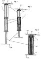
- the linear drive 1 is designed as a telescopic double spindle drive with a central, drivable coupling element 2, a coupled to the coupling element 2 in operative connection, non-driven, that is fixed with respect to a rotation, first element 3rd and a fixed to the coupling element 2 in Wirkver Struktur, the first element 3 arranged axially opposite, fixed second element 4.
- the first element 3 is formed as a first threaded spindle 5 with a first screw thread 5a.
- the second element 4 is formed as a second threaded spindle 6 with a second spindle thread 6a.
- the second threaded spindle 6 and also the coupling element 2 are presently designed as hollow components, once as a hollow spindle and once as a hollow tube, with a hollow interior 9, in which the first threaded spindle 5 is at least partially retractable.
- the second element 4 is substantially formed as a hollow cylinder.
- the coupling element 2, the first element 3 and the second element 4 are arranged coaxially with each other, so that they give a telescopic structure.
- the coupling element 2 is formed as a spindle nut 7 with a first female thread 7a, which corresponds to the first element 3, more precisely the first spindle thread 5a, and a second female thread 8a, which corresponds to the second spindle thread 6a.
- the two female threads 7a, 8a are axially spaced from each other, wherein the distance substantially corresponds to the length of the threads 5a, 6a of the threaded spindles 5.6 in the longitudinal direction.
- the linear drive 1 comprises an actuator device 10, which comprises an actuator 11 and a coupling part 12.
- the actuator 11 is designed as an (electric) motor which drives the coupling part 12.
- the coupling part 12 is formed as a hollow profile tube, which is engaged via engagement means 13 with the coupling element 2.
- the engagement means 13 as formed not rotationally symmetric contours.
- the coupling part 12 is formed as a hollow profile drive tube, which comprises the coupling element 2 at least partially against rotation, wherein the outer contour of the coupling element 2 is not rotationally symmetrical, as well as the inner contour of the drive tube (corresponding coupling part 12).
- the Profurntriebsrohr is designed as a square tube.
- the drive tube 12 the first threaded spindle 5 is arranged, and partially the coupling element 2.
- the drive tube 12 is also arranged coaxially with the coupling element 2 and the two threaded spindles 3 and 4.
- a three-part linear drive 1 is formed with actuator 10. Special bearings or bearing elements, in particular axial bearings for absorbing axial forces, are not required for the mounting of the elements 3, 4.
- the linear drive 1 is shown substantially in a maximum extension length.
- the second threaded spindle 6 has at its end located in the coupling element 2 a stop 2a which abuts against a corresponding section of the coupling element 2 from the inside when an adjustable maximum extension distance is reached.
- FIG. 2 is the linear actuator 1 after Fig. 1 only partially retracted or extended.
- the components of the linear drive 1, the coupling element 2 and the two elements 3, 4 are driven into one another, so that only a minimum installation space for the linear drive 1 is required.
- the coupling element 2 and the second threaded spindle 6 are retracted into the drive tube 12.
- the linear drive 1 In the longitudinal direction, that is in the axial direction, the length of the linear drive 1 is approximately equal to the axial length of the first threaded spindle 5.
- the linear drive 1 more precisely the coupling element 2 at its remote from the actuator 11 end a drive 14, via which an adjustment unit with the linear drive 1 can be coupled.
- a hatched area is shown at the top and bottom of the linear drives 1, respectively.
- This area represents, for example, components that are adjustable relative to each other via the linear drive 1, in particular in the axial direction of the linear drive 1.
- the hatched area indicates that the actuator is fixed relative to the hatched area.
- the hatched area represents an adjustment unit 16, which comprises a first adjustment part 17 and a second adjustment part 18, which are adjustable relative to one another, in particular in the axial direction.
- the adjustment unit 16 is coupled via the driver 14 with the linear drive 1 and can be adjusted accordingly. Is a non-rotating guide device 15 ( Fig4-6 ), so the linear drive must not be rotationally fixed with respect to the hatched area 18, since the guide means 15 prevents co-rotation with the coupling element 2.
- Figures 4-6 show the linear drive 1 with an additional support and guide sleeve 15.
- the linear actuator 1 corresponds to Fig. 4-6 to the linear drive Fig. 1-3
- the support guide sleeve 15 is preferably arranged in the coupling element 2 and causes easier threading of the first threaded spindle 5 in the second threaded spindle 6 at a retraction of the linear drive 1.
- the support guide sleeve 15 cylindrical, so that it can be arranged to save space in the linear drive 1.
- FIGS. 7 to 9 show another embodiment of the linear actuator 1, wherein the coupling element 2 and the elements 3,4 with respect to their execution Fig. 1-3 differ.
- the coupling element 2 is in the Fig. 7-9 formed as a drivable threaded spindle 5, more precisely as a double-threaded spindle 5.
- the double-threaded spindle 5 is formed in a circumferentially outer region as a hollow spindle. In an inner region located therein, the double-threaded spindle 5 can be formed as a full-threaded spindle or as a hollow threaded spindle.
- the threaded spindle 5 in the inner region formed as a hollow spindle to receive the coupling member 12 of the actuator 10 operatively connected therein.
- the threaded spindle 5 has a first spindle thread 5a, which is designed as an external thread.
- the threaded spindle 5 in the inner region, a second spindle thread 6a, which is also designed as an external thread, but in opposite directions to the other external thread.
- the threaded spindle 5 points in the Fig. 7-9 So two threaded spindle sections, which are multi-part, preferably formed in one piece.
- the elements 3, 4 are in the Fig. 7-9 formed as a spindle nuts 7.8, more precisely as fixed tailpipes, in particular as a round or profile tubes with corresponding female thread sections, which cooperate with the corresponding, corresponding thread of the coupling element 2.
- first element 3 which essentially form the linear drive 1
- second element 4 which essentially form the linear drive 1
- the first element 3 is designed as a first threaded spindle 5, in particular as a hollow spindle.
- the coupling element 2 is formed as a second threaded spindle 6, wherein it is formed in an outer region as a hollow spindle and in an inner region as a profile tube or as a profiled bar, each with a corresponding thread.
- the second element 4 is formed as a spindle nut 7, which has a corresponding female thread 7a on a region located to the coupling element 2.
Landscapes
- Engineering & Computer Science (AREA)
- General Engineering & Computer Science (AREA)
- Mechanical Engineering (AREA)
- Transmission Devices (AREA)
Abstract
Description
- Die Erfindung betrifft einen Linearantrieb, insbesondere einen Spindelantrieb nach dem Oberbegriff des Anspruchs 1. Weiter betrifft die Erfindung eine Verstelleinheit mit einem Linearantrieb gemäß Anspruch 12.
- Aus dem Stand der Technik sind allgemein verschiedene Linearantriebe bekannt. Aus der
DE 2920133 B1 ist eine Hubvorrichtung mit mindestens zwei gegeneinander teleskopartig ausfahrbaren Gewindespindeln und mit diesen zusammenwirkenden, an den Gewindespindeln längs verstellbaren, umdrehbaren Muttern bekannt. Hierbei ist eine erste Gewindespindel angetrieben, wobei der Antrieb der zweiten Gewindespindel über eine Gleitführung durch die erste Gewindespindel erfolgt und die zweite Gewindespindel sich auf der ersten Gewindespindel abstützt. Die beiden sich im Wesentlichen über die Höhe der Hubvorrichtung in deren eingefahrenen Zustand erstreckenden Gewindespindeln sind unmittelbar ineinander angeordnet, wobei die Gewindespindeln durch eine Nut- und Federführung oder eine Mehrkantringführung axial beweglich (verschiebbar) und drehfest miteinander verbunden sind. - Die Hubvorrichtung ist relativ komplex aufgebaut und erfordert viele Bauteile. Zudem erfolgt der Antrieb ausschließlich über die erste Gewindespindel.
- Es ist deshalb eine Aufgabe der vorliegenden Erfindung, einen Linearantrieb sowie Möbelstücke mit Linearantrieb zu schaffen, bei welchem ein einfacherer Aufbau, insbesondere mit weniger Bauteilen, realisiert ist.
- Diese und weitere Aufgaben werden ausgehend von einem Linearantrieb nach Anspruch 1 und einer Verstelleinheit nach Anspruch 12 in Verbindung mit deren Merkmalen gelöst.
- Vorteilhafte Weiterbildungen der Erfindung sind in den abhängigen Ansprüchen angegeben oder werden nachstehend im Zusammenhang mit der Beschreibung der Figuren angegeben.
- Die Erfindung schließt die technische Lehre ein, dass bei einem Linearantrieb, insbesondere einem Spindelantrieb, mit einem mittigen, antreibbaren Kopplungselement, einem mit dem Kopplungselement in Wirkverbindung gekoppelten, insbesondere rotationsfesten, ersten Element und einem mit dem Kopplungselement in Wirkverbindung gekoppelten, dem ersten Element axial gegenüber angeordneten, insbesondere feststehenden, zweiten Element, wobei eine Kopplung der Elemente mit dem Kopplungselement über entsprechende Gewindepaarungen erfolgt, vorgesehen ist, dass die Gewindepaarungen als gegenläufige Gewindepaarungen ausgebildet sind, um einen kompakten, im Wesentlichen dreiteiligen Linearantrieb mit einem maximalen Verfahrweg zu schaffen. Feststehend bedeutet, dass das erste Element und das zweite Element rotationsfest in Bezug auf das Kopplungselement ausgebildet sind. Das erste Element und das zweite Element sind durch Rotation des Kopplungselements in deren Axialrichtung in Relation zu dem Kopplungselement bewegbar.
- Durch die gegenläufigen Gewindepaarungen lässt sich der Linearantrieb als Teleskoplinearantrieb ausbilden, das heißt, die beiden gegenüberstehenden feststehenden Elemente lassen sich über das bewegbare Kopplungselement auseinander bewegen, das heißt in Axialrichtung längs verschieben. Über das zentrale, angetriebene Kopplungselement ist ein synchrones Ausfahren, das heißt axiales Bewegen relativ zu dem Kopplungselement, der Elemente über einen Antrieb realisierbar. Die Elemente können als Hohlelemente oder als Vollelemente ausgebildet sein.
- In einer Ausführungsform der vorliegenden Erfindung ist vorgesehen, dass das erste Element als eine erste Gewindespindel mit einem ersten Spindelgewinde, das zweite Element als eine zweite Gewindespindel mit einem zweiten Spindelgewinde und das Kopplungselement als eine Spindelmutter mit je einem zu jedem Spindelgewinde korrespondierenden, mit dem entsprechenden Spindelgewinde zusammenwirkenden Muttergewinde ausgebildet ist, wobei eine erste Gewindepaarung umfassend das erste Spindelgewinde und ein korrespondierendes erstes Muttergewinde gegenläufig zu einer zweiten Gewindepaarung umfassend das zweite Spindelgewinde und ein korrespondierendes zweites Muttergewinde ausgebildet ist.
- Eine andere Ausführungsform der vorliegenden Erfindung sieht vor, dass das erste Element als eine erste Spindelmutter mit einem ersten Muttergewinde, das zweite Element als eine zweite Spindelmutter mit einem zweiten Muttergewinde und das Kopplungselement als eine Gewindespindel mit je einem zu jedem Muttergewinde korrespondierenden, mit dem entsprechenden Muttergewinde zusammenwirkenden Spindelgewinde (-abschnitt) ausgebildet ist, wobei eine erste Gewindepaarung umfassend das erste Muttergewinde und ein korrespondierendes erstes Spindelgewinde gegenläufig zu einer zweiten Gewindepaarung umfassend das zweite Muttergewinde und ein korrespondierendes zweites Spindelgewinde ausgebildet ist. Die Gewindespindel weist zwei unterschiedliche Gewinde auf. Dabei können die Gewinde hintereinander an einer gleichen Fläche ausgebildet sein. Alternativ können die Gewinde an unterschiedlichen Flächen ausgebildet sein. Auch können die Gewinde an der gleichen Fläche überlagert ausgebildet sein. Die Gewindespindel kann bevorzugt als Doppelgewindespindel ausgebildet sein.
- In wiederum einer anderen Ausführungsform der vorliegenden Erfindung ist vorgesehen, dass das erste Element als eine erste Gewindespindel mit einem ersten Spindelgewinde, das zweite Element als eine zweite Spindelmutter mit einem zweiten Muttergewinde und das Kopplungselement als eine Gewinde-Mutter-Spindel mit einem ersten Muttergewinde, welches mit dem ersten Spindelgewinde zusammenwirkt, und einem zweiten Spindelgewinde, welches mit dem zweiten Muttergewinde zusammenwirkt, ausgebildet ist, wobei eine erste Gewindepaarung umfassend das erste Muttergewinde und ein korrespondierendes erstes Spindelgewinde gegenläufig zu einer zweiten Gewindepaarung umfassend das zweite Muttergewinde und ein korrespondierendes zweites Spindelgewinde ausgebildet ist.
- Noch eine andere Ausführungsform der vorliegenden Erfindung sieht vor, dass das zweite Element als eine erste Gewindespindel mit einem ersten Spindelgewinde, das erste Element als eine zweite Spindelmutter mit einem zweiten Muttergewinde und das Kopplungselement als eine Gewinde-Mutter-Spindel mit einem ersten Muttergewinde, welches mit dem ersten Spindelgewinde zusammenwirkt, und einem zweiten Spindelgewinde, welches mit dem zweiten Muttergewinde zusammenwirkt, ausgebildet ist, wobei eine erste Gewindepaarung umfassend das erste Muttergewinde und ein korrespondierendes erstes Spindelgewinde gegenläufig zu einer zweiten Gewindepaarung umfassend das zweite Muttergewinde und ein korrespondierendes zweites Spindelgewinde ausgebildet ist. Diese Ausführungsform stellt die Umkehrung des unmittelbar zuvor aufgeführten Ausführungsbeispiel dar.
- Es sind somit verschiedene Kombinationen des Linearantriebs mit den drei Bauteilen Kopplungselement, erstes Element und zweites Element realisierbar.
- In einer weiteren Ausführungsform der vorliegenden Erfindung ist vorgesehen, dass die beiden Elemente koaxial zueinander ausgerichtet sind. Zwar können die Elemente auch versetzt zueinander ausgebildet werden, jedoch ist es für einen einfachen Aufbau bevorzugt, dass die Elemente koaxial zueinander angeordnet sind.
- In noch einer weiteren Ausführungsform der vorliegenden Erfindung ist vorgesehen, dass mindestens eines der beiden Elemente als Hohlelement mit einem Hohlinnenraum ausgebildet ist, in welchem das andere Element zumindest teilweise einfahrbar ist. Auf diese Weise lässt sich ein maximaler Ausfahrweg bei einem minimalen Platzbedarf realisieren. Durch ein Anordnen der Bauteile ineinander, lässt sich eine geringe Einbauhöhe realisieren. Der mit dem erfindungsgemäßen Linearantrieb realisierbar Hub entspricht etwa der zweifachen Einbauhöhe.
- Noch ein weiteres Ausführungsbeispiel der vorliegenden Erfindung sieht vor, dass die Gewinde im Wesentlichen die gleiche Gewindesteigung bei gegenläufiger Spindelpaarung-Gewinderichtung aufweisen, sodass ein synchroner Betrieb, das heißt, ein synchrones Ausfahren realisierbar ist. Bei einem Antrieb des Kopplungselements werden die Elemente axial im Wesentlichen gleichermaßen bewegt, also etwa im Verhältnis 1:1. Durch unterschiedliche Gewindesteigungen ließen sich andere, beliebige Verhältnisse realisieren.
- In noch einem weiteren Ausführungsbeispiel der vorliegenden Erfindung ist vorgesehen, dass mindestens eines der Elemente einen Anschlag zur Begrenzung einer Linearbewegung des Linearantriebs aufweist. Hierdurch lässt sich ein Ausfahrweg auf einfache Weise begrenzen. Der Anschlag kann verschiebbar oder fest ausgebildet sein. Ein geeignetes Material für den Anschlag ist zum Beispiel ein elastisches Material wie Gummi, Hartgummi und dergleichen. Alternativ kann als Material für den Anschlag ein festes Material wie Stahl, Metall oder dergleichen ausgewählt sein. In einer bevorzugten Ausführungsform ist der Anschlag als Ring, insbesondere als Sprengring oder Segering ausgebildet. Der Anschlag kann insbesondere in einer bewegbaren, das heißt nicht ortsfesten, Anordnung zur Justierung des Linearantriebs fungieren. Insbesondere lässt sich über den Anschlag eine Steuerung justieren, zum Beispiel bei einem Erstbetrieb oder bei einer Nachjustierung. Weiter kann der Anschlag als Einbau- und/oder Montagehilfe genutzt werden. Der Anschlag kann an einer beliebigen Position an einem der Elemente angeordnet werden, beispielsweise an einem Ende benachbart zu dem Kopplungselement oder an dem zu dem Kopplungselement abgewandten Ende.
- Ein Ausführungsbeispiel der vorliegenden Erfindung sieht vor, dass der Linearantrieb mindestens eine Führungseinrichtung zur Führung mindestens eine(r)s der Elemente aufweist. Durch die Führung lassen sich insbesondere längliche Elemente verwenden, welche ohne Führungseinrichtung einem Ausknicken ausgesetzt sind. Die Führungseinrichtung kann weiter die Laufeigenschaft des Linearantriebs verbessern. Es können mehrere Führungseinrichtungen vorgesehen sein. Die Führungseinrichtung kann beispielsweise als Profilrohr ausgebildet sein, beispielsweise als ein Profilrohr mit nicht rotationssymmetrischem Querschnitt. In dem letzteren Fall kann die Führungseinrichtung, insbesondere in Form eines Profilrohrs mit nicht rotationssymmetrischem Querschnitt als Verdrehsicherung verwendet werden. Die Verdrehsicherung bewirkt, dass sich das entsprechende Element nicht mit dem Kopplungselement mitdreht. Somit kann der Linearantrieb an einem Element drehfest mit einem weiteren Bauteil wie einem Möbelstück oder dergleichen angeordnet sein. Das andere Element kann gegen ein Mitdrehen mit dem Kopplungselement über die Führungseinrichtung gesichert sein. Dies ist insbesondere dann von Vorteil, wenn der Linearantrieb in einem Tischbein zum Einsatz kommt, insbesondere bei rotationssymmetrischen Tischbeinen. Das dann auf dem Boden aufstehende Element kann sich bei unzureichender Anpresskraft ohne Führungseinrichtung bei einem Verstellen auf dem Boden drehen, sodass Schleifspuren entstehen. Durch die Verdrehsicherung kann der Tisch in der Höhe verstellt werden, ohne dass sich das den Boden kontaktierende Element oder das dem Boden zugeordnete Element sich mit dem Kopplungselement mitdreht. Die Führungseinrichtung kann als Abstützhülse ausgebildet sein, welche zum Beispiel axiale Kräfte aufnehmen kann. Auf die Führungseinrichtung wirken keine axialen Kräfte.
- Ein weiteres Ausführungsbeispiel der vorliegenden Erfindung sieht vor, dass die Führungseinrichtung integriert an mindestens einem der Elemente ausgebildet ist. Hierzu ist kein separates Bauteil erforderlich, sodass der Linearantrieb weiter eine kompakte Bauform mit wenigen Bauteilen aufweist Bei einem Zusammenfahren des Linearantriebs kann die Führungseinrichtung mit zusammengefahren werden. Beispielsweise ist die Führungseinrichtung hierzu teleskopartig ausgebildet. Die Einbauhöhe des Linearantriebs ist allein von der Ausbildung der beiden Elemente und des Kopplungselements abhängig. Eine eventuelle Aktuatoreinrichtungshöhe fließt bei entsprechender Auslegung nicht in die Einbauhöhe des Linearantriebs mit ein.
- Noch ein weiteres Ausführungsbeispiel der vorliegenden Erfindung sieht vor, dass mindestens eine Führungseinrichtung als separates Bauteil in dem Kopplungselement ausgebildet ist. Alternativ zu der Ausbildung an dem Element lässt sich die Führungseinrichtung ebenso an dem Kopplungselement ausbilden. Hierdurch ist eine Führung des Kopplungselements gewährleistet.
- Noch ein weiteres Ausführungsbeispiel der vorliegenden Erfindung sieht vor, dass das Kopplungselement zwei axial zueinander beabstandete Kopplungsbereiche mit jeweils einem entsprechenden Gewinde aufweist, wobei die Gewinde axial fluchtend ausgebildet sind und zu dem jeweiligen Gewinde der Elemente korrespondieren. Die beabstandeten Kopplungsbereiche sind vorzugsweise derart beabstandet, dass dieser Abstand im Wesentlichen der Länge eines der Elemente entspricht.
- Noch ein weiteres Ausführungsbeispiel der vorliegenden Erfindung sieht vor, dass der Abstand der Kopplungsbereiche korrespondierend zu mindestens einer der Längen der Gewinde der Elemente ausgebildet ist, sodass mindestens eines der Gewinde der Elemente im Wesentlichen in einen zwischen den Kopplungsbereichen und einer Kopplungswandung definierten Hohlraum einfahrbar ist. Auf diese Weise lässt sich im zusammengefahrenen Zustand ein kompakter Linearantrieb realisieren.
- In einer Ausführungsform der vorliegenden Erfindung ist weiterhin vorgesehen, dass der Abstand im Wesentlichen korrespondierend zu einer axialen Länge des Hohlinnenraums ausgebildet ist.
- Ein anderes Ausführungsbeispiel der vorliegenden Erfindung sieht vor, dass das Kopplungselement mindestens eine auf einer dem Hohlraum abgewandten Wandungsseite angeordnete Mitnahmeeinrichtung aufweist. Über die Mitnahmeeinrichtung lässt sich das Kopplungselement mit einem zu bewegenden Teil beispielsweise einem Tischbein oder dergleichen koppeln, sodass beispielsweise eine Hubversteliung möglich ist. Der Linearantrieb ist im Wesentlichen dreiteilig ausgebildet mit einem Kopplungselement und zwei Elementen. Wird der Linearantrieb in einem Tischbein oder dergleichen integriert, so ist das Tischbein entsprechend auch dreiteilig auszubilden. Ein mittlerer Teil ist dann über den Mitnehmer gekoppelt, um bei einer Höhenverstellung des Tischbeins das mittlere Teil oder die mittleren Teile in einer vorbestimmten Relativposition zu den andern beiden Teilen des Tischbeins zu positionieren. Insbesondere ist das mittlere Teil derart mit dem Kopplungselement gekoppelt, dass der mittlere Teil stets mittig zu den beiden anderen benachbarten Teilen des Tischbeins angeordnet ist.
- Noch eine weitere Ausführungsform der vorliegenden Erfindung sieht vor, dass weiter eine Aktuatoreinrichtung mit einem Aktuator zum Antreiben des Kopplungselements vorgesehen ist. Während die Elemente feststehen, lässt sich über den Aktuator das Kopplungselement rotieren, wodurch ein axiales Verfahren der Spindeln realisiert ist. Dadurch, dass nur ein Element, nämlich das Kopplungselement, angetrieben wird, ist ein synchrones Auseinanderfahren der Spindeln in axialer Richtung realisierbar. Über die Gewindesteigung lässt sich beispielsweise ein Ausfahrverhältnis der Spindeln oder allgemeiner der Elemente, festlegen. Der Aktuator bzw. die Aktuatoreinrichtung kann direkt an dem Kopplungselement angeordnet sein. Bevorzugt ist der Aktuator an einem Ende des Linearantriebs angeordnet, sodass dieser sich bei einem Einbau an Verstelleinrichtungen wie Tischen versteckt anordnen lässt. Das Kopplungselement ist so ausgebildet, dass weder der Motor noch das Kopplungsteil im Wesentlichen axiale Kräfte des (Linearantriebs bzw.) der antreibenden Last aufnehmen muss, und somit über des Kopplungsteil von dem Linearantrieb in Bezug auf Axialkräfte entkoppelt ist. Die Aktuatoreinrichtung kann derart ausgebildet sein, dass dessen Bauhöhe keinen Einfluss auf die Bauhöhe des Linearantriebs hat. Hierzu kann der Aktuator einen entsprechenden Durchlass aufweisen, durch welchen der Linearantrieb zumindest teilweise durchgesteckt werden kann, insbesondere ein Element des Linearantriebs. Somit umgibt der Aktuator den Linearantrieb. In diesem Durchlass kann ebenfalls das Kopplungsteil angeordnet sein, sodass dieses ebenfalls keinen Einfluss auf die Einbauhöhe des Aktuators hat. Das Kopplungselement kann per Hand angetrieben werden, zum Beispiel auch über eine Kurbel oder ein anderes Hilfsmittel. Bevorzugt ist ein als Elektromotor oder dergleichen ausgebildeter Aktuator vorgesehen.
- Noch ein weiteres Ausführungsbeispiel der vorliegenden Erfindung sieht vor, dass die Aktuatoreinrichtung ein Kopplungsteil zum Koppeln des Aktuators mit dem Kopplungselement aufweist. Über das entsprechende Kopplungsteil wird das Kopplungselement von dem Aktuator angetrieben, das heißt bewegt.
- Noch eine weitere Ausführungsform der vorliegenden Erfindung sieht vor, dass der Kopplungsteil und das Kopplungselement jeweils korrespondierende Eingriffsmittel zum Übertragen einer Antriebskraft von dem Aktuator auf das Kopplungselement aufweisen. Durch den Kopplungsteil wird die Aktuatoreinrichtung in Bezug auf axiale Kräfte des Linearantriebs von dem Linearantrieb entkoppelt. Das Kopplungsteil kann beispielsweise, wie das Kopplungselement auch, als Vierkantrohr ausgebildet sein.
- Eine andere Ausführungsform der vorliegenden Erfindung sieht vor, dass die Eingriffsmittel eine Verdrehsicherung, insbesondere jeweils korrespondierender, nicht rotationssymmetrische Konturen, aufweisen. Hierdurch kann eine verdrehsichere Kraftübertragung durch Ineinanderstecken von Kopplungselement und Kopplungsteil erfolgen.
- Wiederum eine andere Ausführungsform der vorliegenden Erfindung sieht vor, dass der Kopplungsteil als Profilrohr mit einem hohlen Innenraum zur zumindest teilweisen Aufnahme einer der Elemente ausgebildet ist. Auf diese Weise lässt sich eine äußerst kompakte Bauform des Linearantriebs realisieren, indem Teile in dem Innenraum angeordnet sind.
- Zudem lässt sich in einer anderen Ausführungsform der vorliegenden Erfindung vorsehen, dass der Innenraum eine im Wesentlichen zu einer Länge des aufnehmenden Gewindes des Elementes korrespondierende Länge aufweist.
- In bevorzugten Ausführungsformen lässt sich das Kopplungsteil innenliegend anordnen, das heißt, es verläuft zumindest teilweise in einem Hohlraum in den Elementen und/oder des Kopplungselements.
- Die Erfindung schließt weiter die technische Lehre ein, dass bei einer Verstelleinheit, umfassend mindestens ein erstes und ein zweites Verstellteil, welche relativ zueinander verstellbar sind, ein erfindungsgemäßer Linearantrieb zum Verstellen der Verstelleinheit und/oder der daran angeschlossenen Verstelleinheiten vorgesehen ist. Die Verstelleinheit kann eine Möbeleinheit, eine automotive Einheit, eine Lampeneinheit, eine Monitoreinheit oder eine andere beliebige Einheit sein, bei der mindestens zwei Bestandteile axial zueinander gesteuert bewegt werden
- In einer Ausführungsform der vorliegenden Erfindung ist vorgesehen, dass das erste und/oder das zweite Verstellteil einen Verstellteilhohlraum aufweist/aufweisen, in welchem der Linearantrieb zumindest teilweise angeordnet ist. Bevorzugt sind das Kopplungselement und die Elemente in dem Verstellteilhohlraum anzuordnen.
- Noch eine weitere Ausführungsform der vorliegenden Erfindung sieht vor, dass das erste, das zweite oder ein beliebiges Verstellteil über eine Mitnahme des Linearantriebs mit dem Linearantrieb verstellbar gekoppelt ist/sind. Aufgrund der kompakten Bauform lässt sich der Linearantrieb bequem in der Verstelleinheit anordnen.
- Noch eine weitere Ausführungsform der Erfindung sieht vor, dass die Verstelleinheit als Möbelstück ausgebildet ist, ausgewählt aus der Gruppe umfassend: Tischbeine, Stuhlbeine, Regalbeine, Bettenbeine, Bettenverstelleinrichtungen, Computertische und dergleichen.
- Zusammenfassend ist der Linearantrieb im einfachsten Fall aus drei Bauteilen aufgebaut: einem ersten Element, einem zweiten Element und dazwischen mit einem Kopplungselement, welches die beiden Elemente koppelt. Durch rotieren des Kopplungselements werden die beiden Elemente axial bewegt. Das Rotieren kann durch eine Aktuatoreinrichtung erfolgen. Die Aktuatoreinrichtung ist hinsichtlich axialer Kräfte von den drei zuvor aufgeführten Bauteilen entkoppelt. Die Element sind verdrehsicher angeordnet. Dies kann zum Beispiel über eine separate Verdrehsicherung erfolgen, die beispielsweise durch eine Führungseinrichtung realisiert ist. Der Linearantrieb mit Aktuatoreinrichtung und optional mit Führungseinrichtung erfordert keine Axiallagerung zum Aufnehmen axialer Lasten. Die Aufhängung des Linearantriebs kann mittels der Führungseinrichtung, die als Verdrehsicherung ausgebildet ist, einseitig erfolgen, sodass ein Element rotationsfest aufgehängt ist. Ist keine Verdrehsicherung vorgesehen, müssen beide Elemente rotationsfest oder verdrehsicher angeordnet sein. Die Aktuatoreinrichtung wird über eine Steuerung gesteuert. Diese kann bezüglich vorbstimmbarer Ausfahrposition justiert werden, zum Beispiel unter Verwendung eines Anschlags. Hierüber lassen sich beispielsweise Anfangs- und Endposition leicht justieren. Der Linearantrieb ist als Teleskopantrieb ausgebildet. Die drei Bauteile, die sich im Wesentlichen etwa gleich lang ausbilden lassen, können ineinander verfahren werden, so dass sich eine kompakte Bauform im eingefahrenen Zustand ergibt, die in etwa der Länge eines Bauteils entspricht. Der mit diesem Linearantrieb erreichbare maximale Hub entspricht dann etwa der zweifachen Länge des Linearantriebs im eingefahren Zustand. Bei entsprechender Gewindeauslegung (gegenläufig, Gewindesteigung gleich) lässt sich ein synchrones Verfahren des Linearantriebs realisieren.
- Weitere, die Erfindung verbessernde Maßnahmen, sind in den Unteransprüchen angegeben oder ergeben sich aus der nachfolgenden Beschreibung von mindestens einem Ausführungsbeispiel der Erfindung, welches in den Figuren schematisch dargestellt ist. Sämtliche aus den Ansprüchen, der Beschreibung oder der Zeichnung hervorgehenden Merkmale und/oder Vorteile, einschließlich konstruktiver Einzelheiten, räumliche Anordnungen und/oder Verfahrensschritte können sowohl für sich als auch in verschiedensten Kombinationen erfindungswesentlich sein.
- In den Figuren ist Folgendes dargestellt:
- Fig. 1-3
- zeigen schematisch in einer Seitenquerschnittsansicht einen Linearantrieb in einem ausgefahrenen, einem teilweise aus-/bzw. eingefahrenen und einem eingefahrenen Zustand,
- Fig. 4-6
- zeigen schematisch den Linearantrieb nach
Figur 1 in einer Seitenquerschnittsansicht mit einer zusätzlichen Führungseinrichtung und - Fig 7-9
- zeigen schematisch eine andere Ausführungsform des Linearantriebs mit zwei Spindelmuttern und einer (Doppel-)Gewindespindel.
-
Figur 1-3 zeigen schematisch in einer Seitenquerschnittsansicht einen Linearantrieb 1. Der Linearantrieb 1 ist als Teleskop-Doppelspindelantrieb ausgebildet mit einem mittigen, antreibbaren Kopplungselement 2, einem mit dem Kopplungselement 2 in Wirkverbindung gekoppelten, nicht angetriebenen, das heißt in Bezug auf eine Rotation feststehenden, ersten Element 3 und einem mit dem Kopplungselement 2 in Wirkverbildung gekoppelten, dem ersten Element 3 axial gegenüber angeordneten, feststehenden zweiten Element 4. Das erste Element 3 ist als erste Gewindespindel 5 mit einem ersten Spindelgewinde 5a ausgebildet. Das zweite Element 4 ist als eine zweite Gewindespindel 6 mit einem zweiten Spindelgewinde 6a ausgebildet. Die zweite Gewindespindel 6 und auch das Kopplungselement 2 sind vorliegend als hohle Bauteile ausgebildet, einmal als Hohlspindel und einmal als Hohlrohr, mit einem Hohlinnenraum 9, in welchem die erste Gewindespindel 5 zumindest teilweise einfahrbar ist. Somit ist das zweite Element 4 im Wesentlichen als Hohlzylinder ausgebildet. Das Kopplungselement 2, das erste Element 3 und das zweite Element 4 sind koaxial zueinander angeordnet, sodass diese einen teleskopartigen Aufbau ergeben. Das Kopplungselement 2 ist als Spindelmutter 7 mit einem ersten Muttergewinde 7a, welches zu dem ersten Element 3, genauer dem ersten Spindelgewinde 5a korrespondiert, und einem zweiten Muttergewinde 8a, welches zu dem zweiten Spindelgewinde 6a korrespondiert, ausgebildet. Die beiden Muttergewinde 7a, 8a sind axial beabstandet zueinander ausgebildet, wobei der Abstand im Wesentlichen der Länge der Gewinde 5a, 6a der Gewindespindeln 5,6 in Längsrichtung entspricht. Weiter umfasst der Linearantrieb 1 eine Aktuatoreinrichtung 10, welche einen Aktuator 11 und ein Kopplungsteil 12 umfasst. Der Aktuator 11 ist vorliegend als (Elektro-)Motor ausgebildet, welcher das Kopplungsteil 12 antreibt. Das Kopplungsteil 12 ist als Profilhohlrohr ausgebildet, welches über Eingriffsmittel 13 mit dem Kopplungselement 2 im Eingriff steht. Vorliegend sind die Eingriffsmittel 13 als nicht rotationssymmetrische Konturen ausgebildet. Das heißt der Kopplungsteil 12 ist als hohles Profilantriebsrohr ausgebildet, welcher das Kopplungselement 2 zumindest teilweise verdrehsicher umfasst, wobei die Außenkontur des Kopplungselements 2 nicht rotationssymmetrisch ist, wie auch die Innenkontur des Antriebsrohres (entspricht Kopplungsteil 12). Beispielsweise ist das Profuantriebsrohr als Vierkantrohr ausgebildet. In dem Antriebsrohr 12 ist die erste Gewindespindel 5 angeordnet, sowie teilweise das Kopplungselement 2. Das Antriebsrohr 12 ist ebenfalls koaxial zu dem Kopplungselement 2 und den beiden Gewindespindeln 3 und 4 angeordnet. Durch diese Art der Ausführung ist ein dreiteiliger Linearantrieb 1 mit Aktuatoreinrichtung 10 ausgebildet. Spezielle Lagerungen oder Lagerelemente, insbesondere Axiallagerungen zum Aufnehmen axialer Kräfte, sind für die Lagerung der Elemente 3,4 nicht erforderlich. - In
Figur 1 ist der Linearantrieb 1 im Wesentlichen in einer maximalen Ausfahrlänge dargestellt. Um die Ausfahrlänge zu begrenzen, weist vorliegend die zweite Gewindespindel 6 an deren in dem Kopplungselement 2 gelegenen Ende einen Anschlag 2a auf, der von innen bei Erreichen eines einstellbaren maximalen Ausfahrwegs gegen einen korrespondierenden Abschnitt des Kopplungselements 2 anschlägt. - In
Figur 2 ist der Linearantrieb 1 nachFig. 1 nur teilweise ein- bzw. ausgefahren. Hierbei erkennt man, wie die Bauteile des Linearantriebs 1, das Kopplungselement 2 und die beiden Elemente 3,4 ineinander gefahren werden, sodass nur ein minimaler Bauraum für den Linearantrieb 1 erforderlich ist. Zudem werden das Kopplungselement 2 sowie die zweite Gewindespindel 6 in das Antriebsrohr 12 eingefahren. - In
Figur 3 ist schließlich der komplett eingefahrene Linearantrieb 1 zu erkennen. In Längsrichtung, das heißt in axialer Richtung, ist die Länge des Linearantriebs 1 in etwa gleich der axialen Länge der ersten Gewindespindel 5. Um nun mit weiteren, hier nicht dargestellten, Verstelleinheiten zusammenzuwirken, weist der Linearantrieb 1, genauer das Kopplungselement 2 an dessen entfernt zu dem Aktuator 11 gelegenen Ende eine Mitnahme 14 auf, über welche eine Verstelleinheit mit dem Linearantrieb 1 koppelbar ist. Um das teleskopartige Ein- und Ausfahren bei einem Antrieb des Kopplungselements 2 zu gewährleisten, sind die Gewindepaarungen zwischen erster Gewindespindel 5 und Kopplungselement 2, beziehungsweise zweitem Muttergewinde 8 und zweitem Element 4, genauer dem zweiten Spindelgewinde 6a und dem Kopplungselement 2, genauer dem Muttergewinde 8a gegenläufig ausgebildet. Das heißt, vorliegend weist die erste Gewindespindel 5 ein Rechtsgewinde und die zweite Gewindespindel 6 ein Linksgewinde oder umgekehrt auf. - In den Fig. ist am oberen und unteren Ende der Linearantriebe 1 jeweils ein schraffierter Bereich dargestellt. Dieser Bereich repräsentiert zum Beispiel Komponenten, die relativ zueinander über den Linearantrieb 1 verstellbar sind, insbesondere in axiale Richtung des Linearantriebs 1. Insbesondere kennzeichnet der schraffierte Bereich, dass der Aktuator relativ zu dem schraffierten Bereich fixiert ist. Insbesondere stellt der schraffierte Bereich eine Verstelleinheit 16 dar, welche ein erstes Verstellteil 17 und ein zweites Verstellteil 18 umfasst, die relativ zueinander, insbesondere in axialer Richtung, verstellbar sind. Die Verstelleinheit 16 ist über den Mitnehmer 14 mit dem Linearantrieb 1 gekoppelt und kann so entsprechend verstellt werden. Ist eine verdrehsichere Führungseinrichtung 15 (
Fig4-6 ) vorgesehen, so muss der Linearantrieb nicht rotationsfest in Bezug auf den schraffierten Bereich 18 ausgebildet sein, da die Führungseinrichtung 15 ein Mitdrehen mit dem Kopplungselement 2 verhindert. -
Figuren 4-6 zeigen den Linearantrieb 1 mit einer zusätzlichen Stütz- und Führungshülse 15. Im Übrigen entspricht der Linearantrieb 1 nachFig. 4-6 dem Linearantrieb nachFig. 1-3 . Die Stütz-Führungshülse 15 ist bevorzugt in dem Kopplungselement 2 angeordnet und bewirkt ein leichteres Einfädeln der ersten Gewindespindel 5 in die zweite Gewindespindel 6 bei einem Einfahren des Linearantriebs 1. Vorzugsweise ist die Stütz-Führungshülse 15 zylindrisch ausgebildet, sodass diese Platz sparend in dem Linearantrieb 1 angeordnet werden kann. -
Figuren 7 - 9 zeigen eine andere Ausführungsform des Linearantriebs 1, wobei das Kopplungselement 2 und die Elemente 3,4 sich hinsichtlich ihrer Ausführung gegenüberFig. 1-3 unterscheiden. Das Kopplungselement 2 ist in denFig. 7-9 als antreibbare Gewindespindel 5 ausgebildet, genauer als Doppelgewindespindel 5. Die Doppelgewindespindel 5 ist in einem umfänglich äußeren Bereich als Hohlspindel ausgebildet. In einem darin befindlichen inneren Bereich ist die Doppelgewindespindel 5 als Vollgewindespindel oder als Hohlgewindespindel ausbildbar. InFig. 7-9 ist die Doppelgewindespindel 5 im inneren Bereich als Hohlspindel ausgebildet, um das Kopplungsteil 12 der Aktuatoreinrichtung 10 darin wirkverbunden aufzunehmen. In dem äußeren Bereich weist die Gewindespindel 5 ein erstes Spindelgewinde 5a auf, welches als Außengewinde ausgebildet ist. Im inneren Bereich weist die Gewindespindel 5 ein zweites Spindelgewinde 6a auf, welches ebenfalls als Außengewinde ausgebildet ist, jedoch gegenläufig zu dem anderen Außengewinde. Die Gewindespindel 5 weist in denFig. 7-9 also zwei Gewindespindelabschnitte auf, die mehrteilig, bevorzugt einteilig ausgebildet sind. Die Elemente 3, 4 sind in denFig. 7-9 als Spindelmuttern 7,8 ausgebildet, genauer als feste Endrohre, insbesondere als Rund- oder Profilrohre mit entsprechenden Muttergewindeabschnitten, die mit dem entsprechenden, korrespondierenden Gewinde des Kopplungselementes 2 zusammenwirken. - Aus den drei Bauteilen Kopplungselement 2, erstes Element 3, zweites Element 4, die im Wesentlichen den Linearantrieb 1 bilden, lassen sich mit beliebigen Kombinationen der Bauteile weitere Ausführungsformen realisieren.
- Nicht dargestellt ist beispielsweise eine Ausführungsform, die wie folgt aufgebaut ist
- Das erste Element 3 ist als erste Gewindespindel 5, insbesondere als Hohlspindel ausgebildet. Das Kopplungselement 2 ist als zweite Gewindespindel 6 ausgebildet, wobei diese in einem äußeren Bereich als Hohlspindel und in einem inneren Bereich als Profilrohr oder als Profilstab ausgebildet ist, jeweils mit entsprechendem Gewinde. Das zweite Element 4 ist als Spindelmutter 7 ausgebildet, welche an einem zu dem Kopplungselement 2 gelegenen Bereich ein entsprechendes Muttergewinde 7a aufweist.
Claims (15)
- Linearantrieb (1), insbesondere ein Spindelantrieb, mit
einem mittigen, antreibbaren Kopplungselement (2),
einem mit dem Kopplungselement (2) in Wirkverbindung gekoppelten, ersten Element (3) und
einem mit dem Kopplungselement (2) in Wirkverbindung gekoppelten, dem ersten Element (3) axial gegenüber angeordneten, zweiten Element (4), wobei eine Kopplung der Elemente (3,4) mit dem Kopplungselement (2) über entsprechende Gewindepaarungen erfolgt, dadurch gekennzeichnet, dass
die Gewindepaarungen als gegenläufige Gewindepaarungen ausgebildet sind, um einen kompakten, im Wesentlichen dreiteiligen Linearantrieb (1) mit einem maximalen Verfahrweg zu schaffen. , - Linearantrieb (1) nach Anspruch 1, dadurch gekennzeichnet, dass
das erste Element (3) als eine erste Gewindespindel (5) mit einem ersten Spindelgewinde (5a),
das zweite Element (4) als eine zweite Gewindespindel (6) mit einem zweiten Spindelgewinde (6a) und
das Kopplungselement (2) als eine Spindelmutter (7) mit je einem zu jedem Spindelgewinde (5a,6a) korrespondierenden, mit dem entsprechenden Spindeigewinde (5a) zusammenwirkenden Muttergewinde (7a,8a) ausgebildet ist, wobei eine erste Gewindepaarung (5a,7a) umfassend das erste Spindelgewinde (5a) und ein korrespondierendes erstes Muttergewinde (7a) gegenläufig zu einer zweiten Gewindepaarung (6a,8a) umfassend das zweite Spindelgewinde (6a) und ein korrespondierendes zweites Muttergewinde (8a) ausgebildet ist. - Linearantrieb (1) nach Anspruch 1, dadurch gekennzeichnet, dass
das erste Element (3) als eine erste Spindelmutter (7) mit einem ersten Muttergewinde (7a), das zweite Element (4) als eine zweite Spindelmutter (8) mit einem zweiten Muttergewinde (8a) und
das Kopplungselement (2) als eine Gewindespindel (5) mit je einem zu jedem Muttergewinde (7a,8a) korrespondierenden, mit dem entsprechenden Muttergewinde (7a,8a) zusammenwirkenden Spindelgewinde (5a,6a) ausgebildet ist, wobei eine erste Gewindepaarung (5a,7a) umfassend das erste Muttergewinde (7a) und ein korrespondierendes erstes Spindelgewinde (5a) gegenläufig zu einer zweiten Gewindepaarung (8a,6a) umfassend das zweite Muttergewinde (8a) und ein korrespondierendes zweites Spindelgewinde (6a) ausgebildet ist. - Linearantrieb (1) nach Anspruch 1, dadurch gekennzeichnet, dass
das erste Element (3) als eine erste Gewindespindel (5) mit einem ersten Spindelgewinde (5a),
das zweite Element (4) als eine zweite Spindelmutter (8) mit einem zweiten Muttergewinde (8a) und
das Kopplungselement (2) als eine Gewinde-Mutter-Spindel mit einem ersten Muttergewinde (7a), welches mit dem ersten Spindelgewinde (5a) zusammenwirkt, und einem zweiten Spindelgewinde (6a), welches mit dem zweiten Muttergewinde (8a) zusammenwirkt, ausgebildet ist, wobei eine erste Gewindepaarung (5a,7a) umfassend das erste Muttergewinde (7a) und ein korrespondierendes erstes Spindelgewinde (5a) gegenläufig zu einer zweiten Gewindepaarung (8a,6a) umfassend das zweite Muttergewinde (8a) und ein korrespondierendes zweites Spindelgewinde (6a) ausgebildet ist - Linearantrieb (1) nach Anspruch 1, dadurch gekennzeichnet, dass
das zweite Element (4) als eine erste Gewindespindel (5) mit einem ersten Spindelgewinde (5a),
das erste Element (3) als eine zweite Spindelmutter (8) mit einem zweiten Muttergewinde (8a) und
das Kopplungselement (2) als eine Gewinde-Mutter-Spindel mit einem ersten Muttergewinde (7a), welches mit dem ersten Spindelgewinde (6a) zusammenwirkt, und einem zweiten Spindelgewinde (6a), welches mit dem zweiten Muttergewinde (8a) zusammenwirkt, ausgebildet ist, wobei eine erste Gewindepaarung (5a,7a) von erstem Muttergewinde (7a) und einem korrespondierenden ersten Spindelgewinde (5a) gegenläufig zu einer zweiten Gewindepaarung (8a,6a) umfassend das zweite Muttergewinde (8a) und ein korrespondierendes zweites Spindelgewinde (6a) ausgebildet ist. - Linearantrieb (1) nach einem der vorherigen Ansprüche 1 bis 5, dadurch gekennzeichnet, dass
mindestens eine der beiden Elemente (3,4) als Hohlelement mit einem Hohlinnenraum (9) ausgebildet ist, in welchen das andere Element (4,3) zumindest teilweise einfahrbar ist - Linearantrieb (1) nach einem der vorherigen Ansprüche 1 bis 6, dadurch gekennzeichnet, dass
der Linearantrieb (1) mindestens eine Führungseinrichtung (15) zur Führung mindestens einer der Elemente (3,4) aufweist. - Linearantrieb (1) nach einem der vorherigen Ansprüche 1 bis 7, dadurch gekennzeichnet, dass
das Kopplungselement (2) zwei axial zueinander beabstandete Kopplungsbereiche mit jeweils einem entsprechenden Gewinde aufweist, wobei die Gewinde axial fluchtend ausgebildet sind und zu dem jeweiligen Gewinde der Elemente (3,4) korrespondieren. - Linearantrieb (1) nach einem der vorherigen Ansprüche 1 bis 8, dadurch gekennzeichnet, dass
der Abstand der Kopplungsbereiche korrespondierend zu mindestens einer der Längen der Gewinde der Elemente (3,4) ausgebildet ist, sodass mindestens eines der Gewinde der Elemente (3,4) im Wesentlichen in einen zwischen den Kopplungsbereichen und einer Kopplungswandung definierten Hohlraum einfahrbar ist. - Linearantrieb (1) nach einem der vorherigen Ansprüche 1 bis 9, dadurch gekennzeichnet, dass
das Kopplungselement (2) mindestens eine auf einer dem Hohlraum abgewandten Wandungsseite angeordnete Mitnahmeeinrichtung (14) aufweist. - Linearantrieb (1) nach einem der vorherigen Ansprüche 1 bis 10, dadurch gekennzeichnet, dass
weiter eine Aktuatoreinrichtung (10) mit einem Aktuator (11) zum Antreiben des Kopplungselements (2) vorgesehen ist. - Verstelleinheit (16) umfassend mindestens ein erstes und ein zweites Verstellteil (17,18), welche relativ zueinander verstellbar sind mit einem Linearantrieb (1) nach einem der der vorherigen Ansprüche 1 bis 11 zum Verstellen der Verstelleinheit (16) und/oder der daran angeschlossenen Verstelleinheiten.
- Verstelleinheit (16) nach Anspruch 12, dadurch gekennzeichnet, dass das erste und/oder das zweite Verstellteil (17,18) einen Verstellteilhohlraum aufweist, in welchem der Linearantrieb (1) zumindest teilweise angeordnet ist.
- Verstelleinheit (16) nach Anspruch 12 oder 13, dadurch gekennzeichnet, dass
das erste und/oder das zweite Verstellteil (17,18) über eine Mitnahme (14) des Linearantriebs (1) mit dem Linearantrieb (1) verstellbar gekoppelt ist. - Verstelleinheit (16) nach einem der vorherigen Ansprüche 12 bis 14, dadurch gekennzeichnet, dass
die Verstelleinheit (16) als Möbelstück ausgebildet ist, ausgewählt aus der Gruppe umfassend: Tischbeine, Stuhlbeine, Regalbeine, Bettenbeine, Bettenverstelleinrichtungen, Computertische und dergleichen.
Applications Claiming Priority (1)
| Application Number | Priority Date | Filing Date | Title |
|---|---|---|---|
| DE102008033887A DE102008033887B4 (de) | 2008-07-18 | 2008-07-18 | Teleskop-Doppelspindelantrieb |
Publications (3)
| Publication Number | Publication Date |
|---|---|
| EP2146114A2 true EP2146114A2 (de) | 2010-01-20 |
| EP2146114A3 EP2146114A3 (de) | 2011-08-17 |
| EP2146114B1 EP2146114B1 (de) | 2019-10-16 |
Family
ID=41258118
Family Applications (1)
| Application Number | Title | Priority Date | Filing Date |
|---|---|---|---|
| EP09009298.2A Not-in-force EP2146114B1 (de) | 2008-07-18 | 2009-07-16 | Teleskop-Doppelspindelantrieb |
Country Status (5)
| Country | Link |
|---|---|
| US (1) | US8601889B2 (de) |
| EP (1) | EP2146114B1 (de) |
| DE (1) | DE102008033887B4 (de) |
| DK (1) | DK2146114T3 (de) |
| HU (1) | HUE048587T2 (de) |
Cited By (3)
| Publication number | Priority date | Publication date | Assignee | Title |
|---|---|---|---|---|
| WO2015172962A1 (de) * | 2014-05-14 | 2015-11-19 | Meamedical Ag | Dosiervorrichtung für die abgabe von medikamentenfluid aus einem reservoir mit spindelstange zur verschiebung des kolbens |
| WO2015172828A1 (de) * | 2014-05-14 | 2015-11-19 | Meamedical Ag | Spindelvorrichtung für einen kolben eines reservoirs mit medikamentenfluid |
| EP4241887A1 (de) * | 2022-03-11 | 2023-09-13 | Brand Gmbh + Co Kg | Pipettiervorrichtung |
Families Citing this family (30)
| Publication number | Priority date | Publication date | Assignee | Title |
|---|---|---|---|---|
| US9173997B2 (en) | 2007-10-02 | 2015-11-03 | Medimop Medical Projects Ltd. | External drug pump |
| US9656019B2 (en) | 2007-10-02 | 2017-05-23 | Medimop Medical Projects Ltd. | Apparatuses for securing components of a drug delivery system during transport and methods of using same |
| KR101075319B1 (ko) * | 2008-05-21 | 2011-10-19 | 삼성에스디아이 주식회사 | 리튬이온 이차전지용 전해액 및 이를 포함하는 리튬이온이차전지 |
| CN102278439A (zh) * | 2010-06-08 | 2011-12-14 | 朱豪东 | 一种伸缩式机械结构 |
| US9764464B2 (en) * | 2011-08-03 | 2017-09-19 | The Boeing Company | Robot including telescopic assemblies for positioning an end effector |
| EP2823198A4 (de) * | 2012-03-08 | 2015-11-18 | Thomson Ind Inc | Teleskopischer linearaktuator mit schneckenantrieb |
| DE102012102298B4 (de) * | 2012-03-19 | 2015-10-29 | Logicdata Electronic & Software Entwicklungs Gmbh | Linearaktuator und höhenverstellbarer Tisch |
| DE102012013979A1 (de) * | 2012-07-13 | 2014-01-16 | Logicdata Electronic & Software Entwicklungs Gmbh | Linaearaktuator und Verfahren zum Herstellen eines Linearaktuators |
| TWM459317U (zh) * | 2013-03-28 | 2013-08-11 | Timotion Technology Co Ltd | 具雙螺桿之線性傳動裝置 |
| US9366379B2 (en) * | 2013-12-05 | 2016-06-14 | Innovative Office Products, Llc | Sit-stand workstation with display support apparatus |
| US9987432B2 (en) | 2015-09-22 | 2018-06-05 | West Pharma. Services IL, Ltd. | Rotation resistant friction adapter for plunger driver of drug delivery device |
| US10576207B2 (en) | 2015-10-09 | 2020-03-03 | West Pharma. Services IL, Ltd. | Angled syringe patch injector |
| JP7044708B2 (ja) | 2015-10-09 | 2022-03-30 | ウェスト ファーマ サービシーズ イスラエル リミテッド | カスタマイズシリンジの充填方法 |
| CN105534096A (zh) * | 2015-12-14 | 2016-05-04 | 无锡市永亿精密铸造有限公司 | 一种伸缩式耐用型柜腿 |
| CN113041432B (zh) | 2016-01-21 | 2023-04-07 | 西医药服务以色列有限公司 | 包括视觉指示物的药剂输送装置 |
| CN109219456B (zh) | 2016-01-21 | 2020-05-15 | 西医药服务以色列有限公司 | 自动注射器中的力牵制 |
| WO2017127215A1 (en) | 2016-01-21 | 2017-07-27 | Medimop Medical Projects Ltd. | Needle insertion and retraction mechanism |
| US11389597B2 (en) * | 2016-03-16 | 2022-07-19 | West Pharma. Services IL, Ltd. | Staged telescopic screw assembly having different visual indicators |
| US11730892B2 (en) | 2016-08-01 | 2023-08-22 | West Pharma. Services IL, Ltd. | Partial door closure prevention spring |
| US11338090B2 (en) | 2016-08-01 | 2022-05-24 | West Pharma. Services IL, Ltd. | Anti-rotation cartridge pin |
| EP3315154B1 (de) | 2016-10-28 | 2021-07-07 | maxon international ag | Zweistufiger teleskopspindelantrieb |
| CN106641148B (zh) * | 2017-01-10 | 2020-09-18 | 浙江捷昌线性驱动科技股份有限公司 | 一种传动总成及升降立柱 |
| EP3630226B1 (de) | 2017-05-30 | 2025-10-22 | West Pharma. Services Il, Ltd. | Modularer antriebsstrang für am körper tragbaren injektor |
| EP3480000B1 (de) * | 2017-11-03 | 2020-12-30 | CL Schutzrechtsverwaltungs GmbH | Pulvermodul |
| CN109678089A (zh) * | 2018-12-29 | 2019-04-26 | 宁波海仕凯驱动科技有限公司 | 一种传动总成及升降立柱 |
| AU2020288432B2 (en) * | 2019-06-04 | 2024-06-13 | ANTEBI, Aviv | Telescopic item and mechanism therefor |
| DE102020113960A1 (de) | 2020-05-25 | 2021-11-25 | Brose Fahrzeugteile Se & Co. Kommanditgesellschaft, Bamberg | Spindelantrieb zur motorischen Verstellung eines Verstellelements eines Kraftfahrzeugs |
| US11624429B1 (en) | 2021-07-28 | 2023-04-11 | The United States Of America As Represented By The Secretary Of The Navy | Compact linear drive mechanism |
| CN113561857A (zh) * | 2021-08-05 | 2021-10-29 | 诺创汽车科技(上海)有限公司 | 推进机构和车辆座椅 |
| US12240421B1 (en) * | 2024-10-02 | 2025-03-04 | Sos Solutions, Inc. | Two speed trailer jack with friction clutch |
Citations (1)
| Publication number | Priority date | Publication date | Assignee | Title |
|---|---|---|---|---|
| DE2920133B1 (de) | 1979-05-18 | 1981-03-12 | Alfred 4072 Wickrath Bautz | Hubvorrichtung mit mindestens zwei gegeneinander teleskopartig ausfahrbaren Gewindespindeln |
Family Cites Families (11)
| Publication number | Priority date | Publication date | Assignee | Title |
|---|---|---|---|---|
| US1532702A (en) * | 1924-11-10 | 1925-04-07 | Lane Brothers Company | Lifting jack |
| DE3910814A1 (de) * | 1989-04-04 | 1990-10-11 | Hasenclever Maschf Sms | Schraubgetriebene linearhubeinheit |
| DE10018742B4 (de) * | 2000-04-15 | 2004-09-16 | OKIN Gesellschaft für Antriebstechnik mbH & Co. KG | Vorrichtung zum Verstellen von relativ zueinander beweglichen Teilen |
| WO2001089981A1 (en) * | 2000-05-22 | 2001-11-29 | Ideassociates (Iom) Limited | Telescopically moving structure |
| DE20108882U1 (de) * | 2001-05-28 | 2002-10-10 | Flamme, Klaus Peter, Dipl.-Ing., 86916 Kaufering | Doppelspindelmotor |
| US6786890B2 (en) * | 2002-01-25 | 2004-09-07 | Novo Nordisk A/S | Linear actuator and a medical delivery device comprising such linear actuator |
| EP1510157A1 (de) * | 2003-09-01 | 2005-03-02 | Goppion S.r.l. | Schaukasten mit verbesserter Öffnungsvorrichtung |
| US7185868B2 (en) * | 2005-01-05 | 2007-03-06 | Gemmy Industries Corporation | Telescopic display stand |
| US7712389B2 (en) * | 2006-05-16 | 2010-05-11 | T-Motion Technology Co., Ltd. | Lifting device having parallel double screw rods |
| US20080028878A1 (en) * | 2006-08-07 | 2008-02-07 | Chia-Jung Wang | Lifting Device having Double Screw Rods |
| US7752932B2 (en) * | 2008-04-06 | 2010-07-13 | Hiwin Mikrosystem Corp. | Linear actuator |
-
2008
- 2008-07-18 DE DE102008033887A patent/DE102008033887B4/de not_active Expired - Fee Related
-
2009
- 2009-07-16 DK DK09009298.2T patent/DK2146114T3/da active
- 2009-07-16 EP EP09009298.2A patent/EP2146114B1/de not_active Not-in-force
- 2009-07-16 HU HUE09009298A patent/HUE048587T2/hu unknown
- 2009-07-17 US US12/505,248 patent/US8601889B2/en not_active Expired - Fee Related
Patent Citations (1)
| Publication number | Priority date | Publication date | Assignee | Title |
|---|---|---|---|---|
| DE2920133B1 (de) | 1979-05-18 | 1981-03-12 | Alfred 4072 Wickrath Bautz | Hubvorrichtung mit mindestens zwei gegeneinander teleskopartig ausfahrbaren Gewindespindeln |
Cited By (3)
| Publication number | Priority date | Publication date | Assignee | Title |
|---|---|---|---|---|
| WO2015172962A1 (de) * | 2014-05-14 | 2015-11-19 | Meamedical Ag | Dosiervorrichtung für die abgabe von medikamentenfluid aus einem reservoir mit spindelstange zur verschiebung des kolbens |
| WO2015172828A1 (de) * | 2014-05-14 | 2015-11-19 | Meamedical Ag | Spindelvorrichtung für einen kolben eines reservoirs mit medikamentenfluid |
| EP4241887A1 (de) * | 2022-03-11 | 2023-09-13 | Brand Gmbh + Co Kg | Pipettiervorrichtung |
Also Published As
| Publication number | Publication date |
|---|---|
| EP2146114B1 (de) | 2019-10-16 |
| DE102008033887B4 (de) | 2012-02-09 |
| EP2146114A3 (de) | 2011-08-17 |
| US20100018334A1 (en) | 2010-01-28 |
| DE102008033887A1 (de) | 2010-01-28 |
| DK2146114T3 (da) | 2020-01-20 |
| HUE048587T2 (hu) | 2020-08-28 |
| US8601889B2 (en) | 2013-12-10 |
Similar Documents
| Publication | Publication Date | Title |
|---|---|---|
| EP2146114B1 (de) | Teleskop-Doppelspindelantrieb | |
| DE60110412T2 (de) | Teleskopische struktur | |
| DE102018119426B4 (de) | Verstellbare Hubsäule und verstellbares Tischsystem | |
| EP3341262B1 (de) | Motorisch verstellbare lenksäule für ein kraftfahrzeug | |
| EP3274611B1 (de) | Vierstufiger teleskopaktor mit gewindetrieb | |
| EP2873344B1 (de) | Möbel mit höhenverstellbarem Bein | |
| DE102012102298B4 (de) | Linearaktuator und höhenverstellbarer Tisch | |
| DE102010000970B4 (de) | Höhenverstellbare Betätigungs-Einrichtung | |
| WO2020007723A1 (de) | Lenksäule für ein kraftfahrzeug | |
| DE3910814C2 (de) | ||
| DE29919877U1 (de) | Elektromotorische Verstelleinrichtung | |
| EP2886506B1 (de) | Hubsäule | |
| DE3146662A1 (de) | Fahrgestell fuer ein fahrzeug mit variabler fahrwerksgeometrie | |
| WO2019102037A1 (de) | Teleskopierbarer linearaktuator und höhenverstellbarer tisch | |
| DE102014218039B3 (de) | Spannvorrichtung | |
| DE202014006383U1 (de) | Stossaggregat | |
| DE29919215U1 (de) | Teleskopantriebseinheit | |
| DE3129101A1 (de) | Laengenveraenderbare vorrichtung zum verstellen der position eines fahrzeugsitzes | |
| DE202006008307U1 (de) | Hubvorrichtung mit Gewindestangen | |
| DE19920672B4 (de) | Lineare Stellvorrichtung | |
| DE102011081340B3 (de) | Stützvorrichtung für einen Sattelanhänger, umfassend einen Spindelmechanismus mit mehrteiliger Spindel, sowie Sattelanhänger mit einer solchen Stützvorrichtung und einer Spindel zur Verwendung in einer Stützvorrichtung | |
| DE102012024805B4 (de) | Teleskopierbarer Spindelantrieb und Tischmöbel mit einem teleskopierbaren Spindelantrieb | |
| DE20210836U1 (de) | Teleskopierbarer Linearantrieb | |
| DE102011055415A1 (de) | Teleskopierbare Hubsäule eines Möbelteils | |
| DE102016002980B4 (de) | Dreigliedriger Schiebeholm |
Legal Events
| Date | Code | Title | Description |
|---|---|---|---|
| PUAI | Public reference made under article 153(3) epc to a published international application that has entered the european phase |
Free format text: ORIGINAL CODE: 0009012 |
|
| AK | Designated contracting states |
Kind code of ref document: A2 Designated state(s): AT BE BG CH CY CZ DE DK EE ES FI FR GB GR HR HU IE IS IT LI LT LU LV MC MK MT NL NO PL PT RO SE SI SK SM TR |
|
| AX | Request for extension of the european patent |
Extension state: AL BA RS |
|
| PUAL | Search report despatched |
Free format text: ORIGINAL CODE: 0009013 |
|
| AK | Designated contracting states |
Kind code of ref document: A3 Designated state(s): AT BE BG CH CY CZ DE DK EE ES FI FR GB GR HR HU IE IS IT LI LT LU LV MC MK MT NL NO PL PT RO SE SI SK SM TR |
|
| AX | Request for extension of the european patent |
Extension state: AL BA RS |
|
| RIC1 | Information provided on ipc code assigned before grant |
Ipc: F16H 25/20 20060101AFI20110711BHEP |
|
| 17P | Request for examination filed |
Effective date: 20120213 |
|
| 17Q | First examination report despatched |
Effective date: 20120320 |
|
| STAA | Information on the status of an ep patent application or granted ep patent |
Free format text: STATUS: EXAMINATION IS IN PROGRESS |
|
| GRAP | Despatch of communication of intention to grant a patent |
Free format text: ORIGINAL CODE: EPIDOSNIGR1 |
|
| STAA | Information on the status of an ep patent application or granted ep patent |
Free format text: STATUS: GRANT OF PATENT IS INTENDED |
|
| INTG | Intention to grant announced |
Effective date: 20190531 |
|
| GRAS | Grant fee paid |
Free format text: ORIGINAL CODE: EPIDOSNIGR3 |
|
| GRAA | (expected) grant |
Free format text: ORIGINAL CODE: 0009210 |
|
| STAA | Information on the status of an ep patent application or granted ep patent |
Free format text: STATUS: THE PATENT HAS BEEN GRANTED |
|
| AK | Designated contracting states |
Kind code of ref document: B1 Designated state(s): AT BE BG CH CY CZ DE DK EE ES FI FR GB GR HR HU IE IS IT LI LT LU LV MC MK MT NL NO PL PT RO SE SI SK SM TR |
|
| REG | Reference to a national code |
Ref country code: GB Ref legal event code: FG4D Free format text: NOT ENGLISH |
|
| REG | Reference to a national code |
Ref country code: CH Ref legal event code: EP |
|
| REG | Reference to a national code |
Ref country code: DE Ref legal event code: R096 Ref document number: 502009015986 Country of ref document: DE |
|
| REG | Reference to a national code |
Ref country code: IE Ref legal event code: FG4D Free format text: LANGUAGE OF EP DOCUMENT: GERMAN |
|
| REG | Reference to a national code |
Ref country code: AT Ref legal event code: REF Ref document number: 1191593 Country of ref document: AT Kind code of ref document: T Effective date: 20191115 |
|
| REG | Reference to a national code |
Ref country code: DK Ref legal event code: T3 Effective date: 20200114 |
|
| REG | Reference to a national code |
Ref country code: SE Ref legal event code: TRGR |
|
| REG | Reference to a national code |
Ref country code: NL Ref legal event code: MP Effective date: 20191016 |
|
| REG | Reference to a national code |
Ref country code: LT Ref legal event code: MG4D |
|
| REG | Reference to a national code |
Ref country code: SK Ref legal event code: T3 Ref document number: E 33176 Country of ref document: SK |
|
| PG25 | Lapsed in a contracting state [announced via postgrant information from national office to epo] |
Ref country code: LT Free format text: LAPSE BECAUSE OF FAILURE TO SUBMIT A TRANSLATION OF THE DESCRIPTION OR TO PAY THE FEE WITHIN THE PRESCRIBED TIME-LIMIT Effective date: 20191016 Ref country code: PL Free format text: LAPSE BECAUSE OF FAILURE TO SUBMIT A TRANSLATION OF THE DESCRIPTION OR TO PAY THE FEE WITHIN THE PRESCRIBED TIME-LIMIT Effective date: 20191016 Ref country code: GR Free format text: LAPSE BECAUSE OF FAILURE TO SUBMIT A TRANSLATION OF THE DESCRIPTION OR TO PAY THE FEE WITHIN THE PRESCRIBED TIME-LIMIT Effective date: 20200117 Ref country code: NO Free format text: LAPSE BECAUSE OF FAILURE TO SUBMIT A TRANSLATION OF THE DESCRIPTION OR TO PAY THE FEE WITHIN THE PRESCRIBED TIME-LIMIT Effective date: 20200116 Ref country code: ES Free format text: LAPSE BECAUSE OF FAILURE TO SUBMIT A TRANSLATION OF THE DESCRIPTION OR TO PAY THE FEE WITHIN THE PRESCRIBED TIME-LIMIT Effective date: 20191016 Ref country code: NL Free format text: LAPSE BECAUSE OF FAILURE TO SUBMIT A TRANSLATION OF THE DESCRIPTION OR TO PAY THE FEE WITHIN THE PRESCRIBED TIME-LIMIT Effective date: 20191016 Ref country code: LV Free format text: LAPSE BECAUSE OF FAILURE TO SUBMIT A TRANSLATION OF THE DESCRIPTION OR TO PAY THE FEE WITHIN THE PRESCRIBED TIME-LIMIT Effective date: 20191016 Ref country code: BG Free format text: LAPSE BECAUSE OF FAILURE TO SUBMIT A TRANSLATION OF THE DESCRIPTION OR TO PAY THE FEE WITHIN THE PRESCRIBED TIME-LIMIT Effective date: 20200116 Ref country code: PT Free format text: LAPSE BECAUSE OF FAILURE TO SUBMIT A TRANSLATION OF THE DESCRIPTION OR TO PAY THE FEE WITHIN THE PRESCRIBED TIME-LIMIT Effective date: 20200217 Ref country code: FI Free format text: LAPSE BECAUSE OF FAILURE TO SUBMIT A TRANSLATION OF THE DESCRIPTION OR TO PAY THE FEE WITHIN THE PRESCRIBED TIME-LIMIT Effective date: 20191016 |
|
| PG25 | Lapsed in a contracting state [announced via postgrant information from national office to epo] |
Ref country code: IS Free format text: LAPSE BECAUSE OF FAILURE TO SUBMIT A TRANSLATION OF THE DESCRIPTION OR TO PAY THE FEE WITHIN THE PRESCRIBED TIME-LIMIT Effective date: 20200224 Ref country code: HR Free format text: LAPSE BECAUSE OF FAILURE TO SUBMIT A TRANSLATION OF THE DESCRIPTION OR TO PAY THE FEE WITHIN THE PRESCRIBED TIME-LIMIT Effective date: 20191016 |
|
| REG | Reference to a national code |
Ref country code: DE Ref legal event code: R097 Ref document number: 502009015986 Country of ref document: DE |
|
| PG2D | Information on lapse in contracting state deleted |
Ref country code: IS |
|
| PG25 | Lapsed in a contracting state [announced via postgrant information from national office to epo] |
Ref country code: EE Free format text: LAPSE BECAUSE OF FAILURE TO SUBMIT A TRANSLATION OF THE DESCRIPTION OR TO PAY THE FEE WITHIN THE PRESCRIBED TIME-LIMIT Effective date: 20191016 Ref country code: RO Free format text: LAPSE BECAUSE OF FAILURE TO SUBMIT A TRANSLATION OF THE DESCRIPTION OR TO PAY THE FEE WITHIN THE PRESCRIBED TIME-LIMIT Effective date: 20191016 Ref country code: CZ Free format text: LAPSE BECAUSE OF FAILURE TO SUBMIT A TRANSLATION OF THE DESCRIPTION OR TO PAY THE FEE WITHIN THE PRESCRIBED TIME-LIMIT Effective date: 20191016 Ref country code: IS Free format text: LAPSE BECAUSE OF FAILURE TO SUBMIT A TRANSLATION OF THE DESCRIPTION OR TO PAY THE FEE WITHIN THE PRESCRIBED TIME-LIMIT Effective date: 20200216 |
|
| PLBE | No opposition filed within time limit |
Free format text: ORIGINAL CODE: 0009261 |
|
| STAA | Information on the status of an ep patent application or granted ep patent |
Free format text: STATUS: NO OPPOSITION FILED WITHIN TIME LIMIT |
|
| REG | Reference to a national code |
Ref country code: HU Ref legal event code: AG4A Ref document number: E048587 Country of ref document: HU |
|
| PG25 | Lapsed in a contracting state [announced via postgrant information from national office to epo] |
Ref country code: IT Free format text: LAPSE BECAUSE OF FAILURE TO SUBMIT A TRANSLATION OF THE DESCRIPTION OR TO PAY THE FEE WITHIN THE PRESCRIBED TIME-LIMIT Effective date: 20191016 Ref country code: SM Free format text: LAPSE BECAUSE OF FAILURE TO SUBMIT A TRANSLATION OF THE DESCRIPTION OR TO PAY THE FEE WITHIN THE PRESCRIBED TIME-LIMIT Effective date: 20191016 |
|
| 26N | No opposition filed |
Effective date: 20200717 |
|
| PG25 | Lapsed in a contracting state [announced via postgrant information from national office to epo] |
Ref country code: SI Free format text: LAPSE BECAUSE OF FAILURE TO SUBMIT A TRANSLATION OF THE DESCRIPTION OR TO PAY THE FEE WITHIN THE PRESCRIBED TIME-LIMIT Effective date: 20191016 |
|
| PG25 | Lapsed in a contracting state [announced via postgrant information from national office to epo] |
Ref country code: MC Free format text: LAPSE BECAUSE OF FAILURE TO SUBMIT A TRANSLATION OF THE DESCRIPTION OR TO PAY THE FEE WITHIN THE PRESCRIBED TIME-LIMIT Effective date: 20191016 |
|
| REG | Reference to a national code |
Ref country code: CH Ref legal event code: PL |
|
| REG | Reference to a national code |
Ref country code: BE Ref legal event code: MM Effective date: 20200731 |
|
| PG25 | Lapsed in a contracting state [announced via postgrant information from national office to epo] |
Ref country code: LU Free format text: LAPSE BECAUSE OF NON-PAYMENT OF DUE FEES Effective date: 20200716 Ref country code: FR Free format text: LAPSE BECAUSE OF NON-PAYMENT OF DUE FEES Effective date: 20200731 Ref country code: CH Free format text: LAPSE BECAUSE OF NON-PAYMENT OF DUE FEES Effective date: 20200731 Ref country code: LI Free format text: LAPSE BECAUSE OF NON-PAYMENT OF DUE FEES Effective date: 20200731 |
|
| PG25 | Lapsed in a contracting state [announced via postgrant information from national office to epo] |
Ref country code: BE Free format text: LAPSE BECAUSE OF NON-PAYMENT OF DUE FEES Effective date: 20200731 |
|
| PG25 | Lapsed in a contracting state [announced via postgrant information from national office to epo] |
Ref country code: IE Free format text: LAPSE BECAUSE OF NON-PAYMENT OF DUE FEES Effective date: 20200716 |
|
| PGFP | Annual fee paid to national office [announced via postgrant information from national office to epo] |
Ref country code: AT Payment date: 20210720 Year of fee payment: 13 |
|
| PGFP | Annual fee paid to national office [announced via postgrant information from national office to epo] |
Ref country code: DK Payment date: 20210721 Year of fee payment: 13 Ref country code: GB Payment date: 20210722 Year of fee payment: 13 Ref country code: HU Payment date: 20210707 Year of fee payment: 13 Ref country code: SE Payment date: 20210721 Year of fee payment: 13 Ref country code: SK Payment date: 20210707 Year of fee payment: 13 Ref country code: DE Payment date: 20210721 Year of fee payment: 13 |
|
| PG25 | Lapsed in a contracting state [announced via postgrant information from national office to epo] |
Ref country code: TR Free format text: LAPSE BECAUSE OF FAILURE TO SUBMIT A TRANSLATION OF THE DESCRIPTION OR TO PAY THE FEE WITHIN THE PRESCRIBED TIME-LIMIT Effective date: 20191016 Ref country code: MT Free format text: LAPSE BECAUSE OF FAILURE TO SUBMIT A TRANSLATION OF THE DESCRIPTION OR TO PAY THE FEE WITHIN THE PRESCRIBED TIME-LIMIT Effective date: 20191016 Ref country code: CY Free format text: LAPSE BECAUSE OF FAILURE TO SUBMIT A TRANSLATION OF THE DESCRIPTION OR TO PAY THE FEE WITHIN THE PRESCRIBED TIME-LIMIT Effective date: 20191016 |
|
| PG25 | Lapsed in a contracting state [announced via postgrant information from national office to epo] |
Ref country code: MK Free format text: LAPSE BECAUSE OF FAILURE TO SUBMIT A TRANSLATION OF THE DESCRIPTION OR TO PAY THE FEE WITHIN THE PRESCRIBED TIME-LIMIT Effective date: 20191016 |
|
| REG | Reference to a national code |
Ref country code: DE Ref legal event code: R119 Ref document number: 502009015986 Country of ref document: DE |
|
| REG | Reference to a national code |
Ref country code: DK Ref legal event code: EBP Effective date: 20220731 |
|
| REG | Reference to a national code |
Ref country code: SE Ref legal event code: EUG |
|
| REG | Reference to a national code |
Ref country code: SK Ref legal event code: MM4A Ref document number: E 33176 Country of ref document: SK Effective date: 20220716 Ref country code: AT Ref legal event code: MM01 Ref document number: 1191593 Country of ref document: AT Kind code of ref document: T Effective date: 20220716 |
|
| GBPC | Gb: european patent ceased through non-payment of renewal fee |
Effective date: 20220716 |
|
| PG25 | Lapsed in a contracting state [announced via postgrant information from national office to epo] |
Ref country code: SE Free format text: LAPSE BECAUSE OF NON-PAYMENT OF DUE FEES Effective date: 20220717 Ref country code: AT Free format text: LAPSE BECAUSE OF NON-PAYMENT OF DUE FEES Effective date: 20220716 |
|
| PG25 | Lapsed in a contracting state [announced via postgrant information from national office to epo] |
Ref country code: SK Free format text: LAPSE BECAUSE OF NON-PAYMENT OF DUE FEES Effective date: 20220716 Ref country code: HU Free format text: LAPSE BECAUSE OF NON-PAYMENT OF DUE FEES Effective date: 20220717 Ref country code: GB Free format text: LAPSE BECAUSE OF NON-PAYMENT OF DUE FEES Effective date: 20220716 Ref country code: DE Free format text: LAPSE BECAUSE OF NON-PAYMENT OF DUE FEES Effective date: 20230201 |
|
| PG25 | Lapsed in a contracting state [announced via postgrant information from national office to epo] |
Ref country code: DK Free format text: LAPSE BECAUSE OF NON-PAYMENT OF DUE FEES Effective date: 20220731 |