EP2146227A2 - Capteur optique - Google Patents
Capteur optique Download PDFInfo
- Publication number
- EP2146227A2 EP2146227A2 EP09007551A EP09007551A EP2146227A2 EP 2146227 A2 EP2146227 A2 EP 2146227A2 EP 09007551 A EP09007551 A EP 09007551A EP 09007551 A EP09007551 A EP 09007551A EP 2146227 A2 EP2146227 A2 EP 2146227A2
- Authority
- EP
- European Patent Office
- Prior art keywords
- optical
- light
- sensor according
- photoreceiver
- optical sensor
- Prior art date
- Legal status (The legal status is an assumption and is not a legal conclusion. Google has not performed a legal analysis and makes no representation as to the accuracy of the status listed.)
- Withdrawn
Links
- 230000003287 optical effect Effects 0.000 title claims abstract description 76
- 238000011144 upstream manufacturing Methods 0.000 claims abstract description 4
- 230000008878 coupling Effects 0.000 claims description 4
- 238000010168 coupling process Methods 0.000 claims description 4
- 238000005859 coupling reaction Methods 0.000 claims description 4
- 230000006978 adaptation Effects 0.000 description 1
- 238000004026 adhesive bonding Methods 0.000 description 1
- 230000001419 dependent effect Effects 0.000 description 1
- 230000000694 effects Effects 0.000 description 1
- 238000004049 embossing Methods 0.000 description 1
- 238000004519 manufacturing process Methods 0.000 description 1
- 239000000463 material Substances 0.000 description 1
- 238000005259 measurement Methods 0.000 description 1
- 229920003023 plastic Polymers 0.000 description 1
- 239000007787 solid Substances 0.000 description 1
Images

Classifications
-
- B—PERFORMING OPERATIONS; TRANSPORTING
- B60—VEHICLES IN GENERAL
- B60S—SERVICING, CLEANING, REPAIRING, SUPPORTING, LIFTING, OR MANOEUVRING OF VEHICLES, NOT OTHERWISE PROVIDED FOR
- B60S1/00—Cleaning of vehicles
- B60S1/02—Cleaning windscreens, windows or optical devices
- B60S1/04—Wipers or the like, e.g. scrapers
- B60S1/06—Wipers or the like, e.g. scrapers characterised by the drive
- B60S1/08—Wipers or the like, e.g. scrapers characterised by the drive electrically driven
- B60S1/0818—Wipers or the like, e.g. scrapers characterised by the drive electrically driven including control systems responsive to external conditions, e.g. by detection of moisture, dirt or the like
- B60S1/0822—Wipers or the like, e.g. scrapers characterised by the drive electrically driven including control systems responsive to external conditions, e.g. by detection of moisture, dirt or the like characterized by the arrangement or type of detection means
- B60S1/0833—Optical rain sensor
- B60S1/0837—Optical rain sensor with a particular arrangement of the optical elements
-
- G—PHYSICS
- G02—OPTICS
- G02B—OPTICAL ELEMENTS, SYSTEMS OR APPARATUS
- G02B3/00—Simple or compound lenses
- G02B3/02—Simple or compound lenses with non-spherical faces
- G02B3/08—Simple or compound lenses with non-spherical faces with discontinuous faces, e.g. Fresnel lens
Definitions
- the present invention relates to an optical sensor including an optical plate which is adapted to make surface contact on a pane, in particular a windshield of a motor vehicle, and at least one photoreceiver which is arranged on the side of the optical plate facing away from the pane.
- Typical examples of such sensors are light sensors for controlling the lighting system in a motor vehicle or solar sensors that supply an input parameter for a climate control, often in combination with a rain sensor for automatic control of the windshield wipers.
- the optical plate which has both convex lens structures and optical waveguides formed therein.
- the lenses focus the light incident on the pane, which is then guided through the optical waveguides and onto the photoreceivers.
- the optical plate With its lens and optical waveguide structures that effect multiple deflections of the light beams, the optical plate has a fairly complex three-dimensional shape in adaptation to the spatial arrangement of the photoreceivers that are usually mounted on a printed circuit board.
- the complexity is especially great and a particularly large amount of space is required when the sensor comprises a plurality of sensor units, for example a rain sensor and light sensors.
- a very much lower complexity and space requirement are achieved when an optical plate is used in which the lens structures are Fresnel lenses.
- a sensor of this type is the subject matter of unpublished document DE 10 2007 036 492.1 .
- Optical sensors typically have a light directional characteristic which is dependent on the desired function. To the extent possible, rain sensors should only receive light which originates from a pulsating light source and is totally reflected on the windshield. Ambient light should be suppressed to the extent possible because it could only affect the measurement of the rain-related events. Light sensors, on the other hand, are designed to selectively receive light incident from specific directions and traversing the windshield, such as, e.g., frontally from a narrow solid angle or else non-directionally. The desired directional characteristic may be attained by taking various measures all of which, however, are involved and require additional space.
- an optical mask is arranged in the optical path upstream of the photoreceiver, the optical mask having light-blocking and light-transmissive surface regions; the light-transmissive surface regions expose an optical path that traverses the optical plate, impinges on the photoreceiver and is delimited by the light-blocking surface regions.
- the optical mask requires no space whatsoever; it may be applied, more particularly printed, directly on the surface of the optical plate facing the photoreceiver or photoreceivers. Since the optical mask may be arranged directly in the optical path upstream of the photoreceivers, an access of any undesirable light components to the photoreceivers, particularly in cooperation with the directional or focusing function of the optical plate, is virtually excluded.
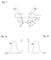
- the optical sensor schematically illustrated in Fig. 1 is intended for mounting on the inside of a windshield 1 and includes two sensor units.
- the sensor is coupled to the surface of the windshield 1 by means of a transparent coupling layer 2, which is, e.g., a transparent rubber or a gel.
- the essential component of the sensor is an optical plate 3 which is made of a transparent plastic material.
- the optical plate 3 On its surface facing away from the windshield 1, the optical plate 3 carries an optical mask 4 which consists of a grid of light-blocking and light-transmissive surface regions.
- a pair of photoreceivers 6a, 6b are coupled to the optical plate 3 and the optical mask 4 by means of a transparent coupling layer 5.
- the windshield 1, the coupling layers 2 and 5, and the optical plate 3 all have the same refractive index.
- any light beams incident on the windshield are directed through in a straight line onto the light-sensitive surfaces of the photoreceivers 6a, 6b.
- the passage of light is limited by the optical mask 4, as is illustrated in Fig. 2 .
- the light-transmissive surface regions of the mask 4 form passage windows that are limited by the light-blocking surface regions.
- the patterned elements are small squares. Contrary to the schematic illustration in Fig. 2 , the edge lengths of the squares are very much smaller than the extent of the light-sensitive surface of the photoreceivers. In this way, a smoothed curve for the directional characteristic is obtained, as illustrated in Figures 1 a and 1 b for two beams of rays 20a and 20b which are incident on the photoreceivers 6a and 6b, respectively.
- Fig. 2 clearly shows the function of the optical mask.
- a light beam 10a which is illustrated by a dotted line, impinges on light-blocking surface regions of the mask and is absorbed.
- a light beam 10b which is illustrated by a solid line, impinges on light-transmissive surface regions of the mask 4 and is allowed to pass to the photoreceiver 6.
- the first and second sensor units in Fig. 1 contain the photoreceivers 6a and 6b, respectively. Both sensor units detect ambient light that is incident on the windshield. But, the first sensor unit has the directional characteristic 20a in Fig. 1 a and the second sensor unit has the directional characteristic 20b in Fig. 1 b.
- the senor comprises further sensor units not shown here, in particular a rain sensor.
- the rain sensor requires lens structures for focusing a light beam from a pulsating light source, which is totally reflected on the windshield.
- the necessary lens structures are configured as Fresnel lenses by stamping or embossing the optical plate 4.
- the Fresnel lenses cooperate with the optical mask, which allows only useful light rays to pass and in this way shields the photoreceivers from an entry of extraneous light.
- the sensor having a plurality of sensor units is of an extremely compact structure. In spite of the complex functions of the sensor, it is very cost-effective to manufacture and, in addition, easy to adjust to the respective requirements of particular applications by appropriately applying the optical mask with light-blocking and light-transmissive surface regions, for example by printing on a surface of the optical plate or by gluing on a film.
Landscapes
- Engineering & Computer Science (AREA)
- Automation & Control Theory (AREA)
- Mechanical Engineering (AREA)
- Photometry And Measurement Of Optical Pulse Characteristics (AREA)
- Investigating Or Analysing Materials By Optical Means (AREA)
- Light Receiving Elements (AREA)
- Photo Coupler, Interrupter, Optical-To-Optical Conversion Devices (AREA)
Applications Claiming Priority (1)
| Application Number | Priority Date | Filing Date | Title |
|---|---|---|---|
| DE102008033204A DE102008033204A1 (de) | 2008-07-15 | 2008-07-15 | Optischer Sensor |
Publications (2)
| Publication Number | Publication Date |
|---|---|
| EP2146227A2 true EP2146227A2 (fr) | 2010-01-20 |
| EP2146227A3 EP2146227A3 (fr) | 2010-02-03 |
Family
ID=41137371
Family Applications (1)
| Application Number | Title | Priority Date | Filing Date |
|---|---|---|---|
| EP09007551A Withdrawn EP2146227A3 (fr) | 2008-07-15 | 2009-06-08 | Capteur optique |
Country Status (7)
| Country | Link |
|---|---|
| US (1) | US8338774B2 (fr) |
| EP (1) | EP2146227A3 (fr) |
| JP (1) | JP5537840B2 (fr) |
| CN (1) | CN101628571B (fr) |
| BR (1) | BRPI0902377A2 (fr) |
| DE (1) | DE102008033204A1 (fr) |
| MX (1) | MX2009007532A (fr) |
Families Citing this family (5)
| Publication number | Priority date | Publication date | Assignee | Title |
|---|---|---|---|---|
| JP5473745B2 (ja) | 2010-04-21 | 2014-04-16 | オムロンオートモーティブエレクトロニクス株式会社 | 光検出装置 |
| JP5953658B2 (ja) | 2011-05-25 | 2016-07-20 | ソニー株式会社 | ロボット制御装置及びロボット装置の制御方法、コンピューター・プログラム、プログラム記憶媒体、並びにロボット装置 |
| DE102015113990A1 (de) | 2015-08-24 | 2017-03-02 | Valeo Schalter Und Sensoren Gmbh | Optische Sensorvorrichtung für ein Kraftfahrzeug, Fahrerassistenzsystem sowie Kraftfahrzeug |
| DE102018115967A1 (de) * | 2018-07-02 | 2020-01-02 | Bcs Automotive Interface Solutions Gmbh | Verfahren sowie Anordnung zur Herstellung einer optischen Baugruppe |
| CN112262042A (zh) | 2019-02-20 | 2021-01-22 | 法国圣戈班玻璃厂 | 具有集成的光传感器的复合玻璃板 |
Citations (1)
| Publication number | Priority date | Publication date | Assignee | Title |
|---|---|---|---|---|
| EP1431142A2 (fr) | 2002-12-20 | 2004-06-23 | Robert Bosch Gmbh | Capteur de pluie, en particulier pour un véhicule et méthode pour sa fabrication |
Family Cites Families (25)
| Publication number | Priority date | Publication date | Assignee | Title |
|---|---|---|---|---|
| FR2571323B1 (fr) * | 1984-10-04 | 1987-01-30 | Saint Gobain Vitrage | Dispositif automatique d'actionnement des organes de nettoyage d'un vitrage de vehicule automobile |
| JPH02238426A (ja) * | 1989-03-10 | 1990-09-20 | Canon Inc | 光信号受信装置 |
| AU648513B2 (en) * | 1989-08-28 | 1994-04-28 | Introlab Pty Limited | Sensing moisture on screen and automated controlled wiping |
| WO1994011703A1 (fr) * | 1992-11-06 | 1994-05-26 | Nippondenso Co., Ltd. | Capteur pyrheliometrique |
| JP3228304B2 (ja) | 1992-12-22 | 2001-11-12 | 日本製紙株式会社 | 電子写真用転写紙 |
| US6084519A (en) * | 1993-05-07 | 2000-07-04 | Control Devices, Inc. | Multi-function light sensor for vehicle |
| FR2722291B1 (fr) * | 1994-07-06 | 1996-10-04 | Valeo Electronique | Dispositif pour la detection d'un etat de surface d'une vitre de vehicule, et notamment pour la detection de las presence de gouttes d'eau sur un pare-brise |
| US5661303A (en) * | 1996-05-24 | 1997-08-26 | Libbey-Owens-Ford Co. | Compact moisture sensor with collimator lenses and prismatic coupler |
| DE19861428B4 (de) * | 1998-03-17 | 2008-01-10 | Robert Bosch Gmbh | Optischer Sensor |
| JPH11295214A (ja) * | 1998-04-14 | 1999-10-29 | Nippon Sheet Glass Co Ltd | 水滴及び光量検出センサ |
| JP2000065726A (ja) * | 1998-08-21 | 2000-03-03 | Nippon Sheet Glass Co Ltd | 液滴検出方法及び装置 |
| FR2787406B1 (fr) * | 1998-12-21 | 2001-02-16 | Valeo Systemes Dessuyage | Procede de commande de nettoyage d'une surface de plaque par controle optique dynamique, et equipement de mise en oeuvre |
| DE19955423A1 (de) * | 1999-11-18 | 2001-05-31 | Hella Kg Hueck & Co | Sensoreinrichtung und Verfahren zur Herstellung einer Sensoreinrichtung |
| AU2002355905A1 (en) * | 2001-08-14 | 2003-03-03 | Keeler Limited | Hand held tonometer with optical arrangement for indicating critical distance from an eye |
| DE10157028A1 (de) * | 2001-11-21 | 2003-06-05 | Bosch Gmbh Robert | Sensoreinrichtung, insbesondere zur Steuerung von Beleuchtungseinrichtungen eines Kraftfahrzeugs |
| JP2003254897A (ja) * | 2002-02-28 | 2003-09-10 | Denso Corp | 雨滴及び光検出装置、及び、オートワイパー装置 |
| DE10218160C1 (de) * | 2002-04-23 | 2003-12-24 | Elmos Semiconductor Ag | Vorrichtung zur Ermittlung des Einfallwinkels einer Strahlung auf eine Strahlungseinfallfläche |
| JP2004096638A (ja) * | 2002-09-03 | 2004-03-25 | Canon Inc | 撮像装置およびその製造方法 |
| DE102004015040A1 (de) * | 2004-03-26 | 2005-10-13 | Robert Bosch Gmbh | Kamera in einem Kraftfahrzeug |
| DE102004033696A1 (de) * | 2004-07-13 | 2006-02-02 | Leopold Kostal Gmbh & Co. Kg | Optoelektronische Sensoreinrichtung |
| JP3935898B2 (ja) * | 2004-07-22 | 2007-06-27 | 竹中電子工業株式会社 | 光電センサ |
| JP4292413B2 (ja) * | 2004-10-12 | 2009-07-08 | 株式会社デンソー | 雨滴検出装置並びにそれを備えたワイパ自動制御装置 |
| JP2007278711A (ja) * | 2006-04-03 | 2007-10-25 | Tgk Co Ltd | 雨滴センサ |
| DE202006005665U1 (de) | 2006-04-05 | 2007-08-16 | Trw Automotive Electronics & Components Gmbh & Co. Kg | Optische Sensorvorrichtung |
| DE102007036492B4 (de) | 2007-08-01 | 2009-07-30 | Trw Automotive Electronics & Components Gmbh & Co. Kg | Optische Sensorvorrichtung |
-
2008
- 2008-07-15 DE DE102008033204A patent/DE102008033204A1/de not_active Withdrawn
-
2009
- 2009-06-08 EP EP09007551A patent/EP2146227A3/fr not_active Withdrawn
- 2009-06-10 JP JP2009138857A patent/JP5537840B2/ja not_active Expired - Fee Related
- 2009-06-22 US US12/488,739 patent/US8338774B2/en not_active Expired - Fee Related
- 2009-07-09 BR BRPI0902377-1A patent/BRPI0902377A2/pt not_active IP Right Cessation
- 2009-07-14 MX MX2009007532A patent/MX2009007532A/es active IP Right Grant
- 2009-07-14 CN CN2009101595704A patent/CN101628571B/zh not_active Expired - Fee Related
Patent Citations (1)
| Publication number | Priority date | Publication date | Assignee | Title |
|---|---|---|---|---|
| EP1431142A2 (fr) | 2002-12-20 | 2004-06-23 | Robert Bosch Gmbh | Capteur de pluie, en particulier pour un véhicule et méthode pour sa fabrication |
Also Published As
| Publication number | Publication date |
|---|---|
| EP2146227A3 (fr) | 2010-02-03 |
| CN101628571B (zh) | 2012-06-27 |
| JP2010025924A (ja) | 2010-02-04 |
| MX2009007532A (es) | 2010-03-22 |
| JP5537840B2 (ja) | 2014-07-02 |
| DE102008033204A1 (de) | 2010-02-04 |
| US20100012824A1 (en) | 2010-01-21 |
| US8338774B2 (en) | 2012-12-25 |
| CN101628571A (zh) | 2010-01-20 |
| BRPI0902377A2 (pt) | 2010-04-20 |
Similar Documents
| Publication | Publication Date | Title |
|---|---|---|
| KR100469605B1 (ko) | 콜리메이터렌즈및분광커플러를갖는소형습기감지기 | |
| EP2020348B1 (fr) | Dispositif de capteur optique | |
| CN101566695B (zh) | 光学传感器件 | |
| JP2012532356A (ja) | 2つの有視範囲へ同時に集束するための光学モジュール | |
| US8338774B2 (en) | Optical sensor with light-blocking and light-transmissive surface regions | |
| DE69838859T2 (de) | Kompakter Feuchtigkeitssensor mit wirksamer, sehr schräggestellter Optik | |
| WO2008063363B1 (fr) | Capteur de pluie multimode | |
| EP0997360A2 (fr) | Fonctionnement d'un capteur de pluie sur verre réfléchissant les rayons solaires | |
| JP2001066246A (ja) | 雨滴センサ | |
| JP4785033B2 (ja) | 光学式水滴センサ | |
| KR970022479A (ko) | 다방향 촬상 카메라장치 | |
| JP4473509B2 (ja) | 特に自動車に用いられるレインセンサ | |
| JP2003504631A (ja) | ガラスの湿り具合検出のためのセンサ装置 | |
| DE60021775D1 (de) | Optischer distanzsensor | |
| US9546900B2 (en) | Optical sensing device for detecting ambient light in motor vehicles comprising a prism structure having a plurality of prisms designed to direct rays of a specific ambient light beam | |
| US7034699B2 (en) | Rain sensor, especially for a motor vehicle | |
| KR20050035185A (ko) | 결로 검출 장치 | |
| JP2008524556A (ja) | センサ装置、例えば車両用センサ装置 | |
| KR20010013512A (ko) | 차창의 습기를 검출하기 위한 센서 장치 | |
| US9709493B2 (en) | Sensor device for detecting moisture on a pane | |
| JP2007139659A (ja) | 雨滴センサ | |
| WO2005095169A1 (fr) | Dispositif detecteur optoelectronique pour vehicule automobile | |
| JP3521062B2 (ja) | 雨滴検出装置 | |
| JP3547044B2 (ja) | ホログラムの露光装置 | |
| CN104597554A (zh) | 防眩光的导光结构及其光学膜片 |
Legal Events
| Date | Code | Title | Description |
|---|---|---|---|
| PUAI | Public reference made under article 153(3) epc to a published international application that has entered the european phase |
Free format text: ORIGINAL CODE: 0009012 |
|
| PUAL | Search report despatched |
Free format text: ORIGINAL CODE: 0009013 |
|
| AK | Designated contracting states |
Kind code of ref document: A2 Designated state(s): AT BE BG CH CY CZ DE DK EE ES FI FR GB GR HR HU IE IS IT LI LT LU LV MC MK MT NL NO PL PT RO SE SI SK TR |
|
| AX | Request for extension of the european patent |
Extension state: AL BA RS |
|
| AK | Designated contracting states |
Kind code of ref document: A3 Designated state(s): AT BE BG CH CY CZ DE DK EE ES FI FR GB GR HR HU IE IS IT LI LT LU LV MC MK MT NL NO PL PT RO SE SI SK TR |
|
| AX | Request for extension of the european patent |
Extension state: AL BA RS |
|
| 17P | Request for examination filed |
Effective date: 20100722 |
|
| 17Q | First examination report despatched |
Effective date: 20100825 |
|
| RAP1 | Party data changed (applicant data changed or rights of an application transferred) |
Owner name: BCS AUTOMOTIVE INTERFACE SOLUTIONS GMBH |
|
| GRAP | Despatch of communication of intention to grant a patent |
Free format text: ORIGINAL CODE: EPIDOSNIGR1 |
|
| INTG | Intention to grant announced |
Effective date: 20200108 |
|
| STAA | Information on the status of an ep patent application or granted ep patent |
Free format text: STATUS: THE APPLICATION IS DEEMED TO BE WITHDRAWN |
|
| 18D | Application deemed to be withdrawn |
Effective date: 20200603 |