EP2146237A1 - Système optique stéréoscopique doté d'un seul projecteur avec des valves ultra légères dans le chemin lumineux - Google Patents
Système optique stéréoscopique doté d'un seul projecteur avec des valves ultra légères dans le chemin lumineux Download PDFInfo
- Publication number
- EP2146237A1 EP2146237A1 EP08160665A EP08160665A EP2146237A1 EP 2146237 A1 EP2146237 A1 EP 2146237A1 EP 08160665 A EP08160665 A EP 08160665A EP 08160665 A EP08160665 A EP 08160665A EP 2146237 A1 EP2146237 A1 EP 2146237A1
- Authority
- EP
- European Patent Office
- Prior art keywords
- light
- pixel
- display panel
- polarization
- cells
- Prior art date
- Legal status (The legal status is an assumption and is not a legal conclusion. Google has not performed a legal analysis and makes no representation as to the accuracy of the status listed.)
- Withdrawn
Links
Images


Classifications
-
- H—ELECTRICITY
- H04—ELECTRIC COMMUNICATION TECHNIQUE
- H04N—PICTORIAL COMMUNICATION, e.g. TELEVISION
- H04N13/00—Stereoscopic video systems; Multi-view video systems; Details thereof
- H04N13/30—Image reproducers
- H04N13/332—Displays for viewing with the aid of special glasses or head-mounted displays [HMD]
- H04N13/337—Displays for viewing with the aid of special glasses or head-mounted displays [HMD] using polarisation multiplexing
-
- G—PHYSICS
- G02—OPTICS
- G02B—OPTICAL ELEMENTS, SYSTEMS OR APPARATUS
- G02B30/00—Optical systems or apparatus for producing three-dimensional [3D] effects, e.g. stereoscopic images
- G02B30/20—Optical systems or apparatus for producing three-dimensional [3D] effects, e.g. stereoscopic images by providing first and second parallax images to an observer's left and right eyes
- G02B30/22—Optical systems or apparatus for producing three-dimensional [3D] effects, e.g. stereoscopic images by providing first and second parallax images to an observer's left and right eyes of the stereoscopic type
- G02B30/25—Optical systems or apparatus for producing three-dimensional [3D] effects, e.g. stereoscopic images by providing first and second parallax images to an observer's left and right eyes of the stereoscopic type using polarisation techniques
Definitions
- the present invention relates to a stereoscopic optical system and a method for displaying stereoscopic images as well as to a controller for controlling a stereoscopic projection system and software for controlling the operation of a stereoscopic projection system.
- Stereoscopic image displays such as stereoscopic projection for example, are based on the same principle: two slightly different images, one for the left eye and one for the right eye, are displayed by some means, e.g. projected onto a screen.
- a corresponding image modulating system enables the left eye to see only the left eye image, and the right eye to see only the right eye image.
- Passive stereo displaying when at least one, but often two projection devices are used to each project images intended to be seen by a different eye, may be based on the principle of different light polarizations or of differences in frequency (colour).
- the viewer wears passive obscuration devices such as non-switchable obscuration devices.
- These may be a pair of glasses with two oppositely polarized lenses or filters, one for the left eye and one for the right eye. The light from each of two projected images is polarized differently and can pass only through its corresponding filter. If the images are provided by means of a single projector, the projector alternates the left eye information with the right eye information at double refresh rate.
- a screen in front of the projector's lenses alternates the polarization of the projected image in such a way that the image of each eye passes only through its corresponding polarizing filter of the pair of passive stereo glasses. If the images are provided by means of two projectors, one projector displays the left eye information and the other display the right eye information, both at a standard refresh rate. A polarizing filter mounted in the optical path of each projector ensures that the correct information passes through its corresponding filter in the pair of passive stereo glasses. If the projectors are LCD projectors, they may be internally polarized, thus eliminating the requirement for external filters.
- the two-projector approach has the added value over the one-projector approach of providing higher brightness.
- Passive obscuration devices have the advantage over active obscuration devices that they are less expensive. 3D animation is often performed for a larger audience, to which obscuration devices are distributed. Obscuration devices often tend to be removed or stolen, which is very annoying in case they are rather expensive, but does not really matter in case they are a cheap pair of glasses with coloured plastic filters as the lenses.
- WO 2006/038819 A1 relates to a stereoscopic display adapted to present a stereoscopic image composed of a plurality of pixels.
- This display includes a light intensity encoder adapted to emit light from a plurality of pixels with an assigned light intensity for each pixel, and a light polarization encoder adapted to receive light emitted from the light intensity encoder and to emit this light with an assigned polarization state for each pixel.
- the display provided is adapted to emit light polarized with a non-spatial polarization.
- the invention disclosed also encompasses a stereoscopic image decoder with each filter to be positioned between a stereoscopic display and an eye of an observer.
- WO 98/25414 A1 discloses an apparatus and a method for generating a stereo image that is perceived as a three-dimensional image when viewed through polarizing spectacles having orthogonally polarized lenses.
- the apparatus includes an illuminator that generates light of variable intensity, a modulator that generates an illumination control signal for controlling the intensity of light emitted by the illuminator, a polarizer for polarizing the light generated by the illuminator, and a distributor for changing the plane of polarization of the polarized light.
- EP 1 830 585 A2 discloses a stereoscopic projection system comprising a projection device with at least one filter which filters a parameter of the light in a colour selective manner.
- the at least one filter which filters a parameter of the light in a colour selective manner has a spectral characteristic for transmitting light in a first wavelength band or set of wavelength bands and for reflecting light in a second wavelength band or set of wavelength bands.
- the projection device comprises a means, such as e.g. a rotating wheel or a sliding filter, for fast synchronized switching between light in different wavelength bands or sets of wavelength bands.
- the present invention provides a stereoscopic optical system comprising: a first display panel subdivided into individually addressable light emitting or transmitting or reflecting, pixels; and a second display panel subdivided into individually addressable light transmitting or reflecting, pixels; the first and second display panel being arranged so that the light emitted from a light emitting or transmitting or reflecting, pixel of the first display may pass through a pre-determined light transmitting or reflecting pixel of the second display; wherein during operation the left eye image and the right eye image of the stereoscopic image are displayed simultaneously on the light emitting or transmitting or reflecting, pixels of the first display panel; wherein each light transmitting or reflecting pixel of the second display is adapted to change the polarization state of the light passing through as a response to a signal addressing the light transmitting or reflecting pixel; wherein a first spectral filter is located in the light path between the first display panel and the second display panel; and wherein the light leaving the second display panel furthermore passes through a polarizer.
- the set of spectral filter, second display panel and polarizer may be considered as a transmittance tunable spectral filter.
- a stereoscopic optical system encompasses both direct view systems or displays and projection systems or displays.
- a method for providing stereoscopic images will encompass both the projection and the direct display of stereoscopic images.
- the main advantage according to the invention is that the perceived stereo quality basically does not depend on polarization. This implies that once the light has passed the last polarizer no particular precautions have to be taken to preserve polarization. In particular it is possible to use heavy scattering screens or diffusers for display purposes.
- the outgoing light displays a modulated spectrum in which information for the left eye is contained in one set of wavelength bands and for the right eye in a complementary set of wavelength bands. Therefore it is possible to use wavelength selective eyewear that does not rely on polarization.
- the present invention provides a method for providing stereoscopic images comprising the steps of:
- the present invention is also related to a controller for controlling a stereoscopic optical system to carry out a method according to the present invention.
- the controller comprises means for controlling a left eye stereo video signal S_l assigned to an individual light emitting, or transmitting or reflecting, pixel, the signal comprising information on the x-coordinate of the pixel, the y-coordinate of the pixel, the wavelength of the light emitted, or transmitted or reflected by the pixel and the intensity of the light emitted, or transmitted or reflected, by the pixel.
- the controller also comprises means for controlling a right eye stereo video signal S_r assigned to an individual light emitting, or transmitting or reflecting, pixel, the signal comprising information on the x-coordinate of the pixel, the y-coordinate of the pixel, the wavelength of the light emitted or transmitted or reflected by the pixel and the intensity of the light emitted or transmitted or reflected by the pixel.
- the controller also comprises means for processing the signals S_l and S_r to yield an intensity information S comprising information on the intensity and the wavelength of light emitted, or transmitted or reflected, from a pixel with x and y coordinates.
- the controller also comprises means for processing the signals S_l and S_r to yield a polarization information P comprising information on the polarization and the wavelength of light emitted or transmitted or reflected from a pixel with x and y coordinates.
- the controller also comprises means for controlling the projection or display of the image to intensity information S on a first projection or display panel and for filtering a parameter of the light in a colour-selective manner, for varying the degree of polarization of the light according to polarization information P on a second projection or display panel and for modulating the amplitude of the light leaving the second projection or display panel in a polarization-selective manner.
- the present invention also includes a stereoscopic optical system comprising a first cholesteric display and a second cholesteric display, wherein the first cholesteric display determines a first eye image and the second cholesteric display defines a second eye image and wherein the first cholesteric display and the second cholesteric display reflect circular polarized light of opposing handedness.
- the first and the second cholesteric display may each comprise red, green and blue pixels.
- the pres invention also includes a stereoscopic optical system comprising a display panel and in the optical path of the light of the display panel a first and a second cholesteric filter, the cholesteric filters comprising individually addressable pixels, wherein the light source is adapted to simultaneously display a left eye image and a right eye image, wherein the light from each pixel of the light source passes through a pre-determined pixel of the first and the second cholesteric filter and wherein the first and the second cholesteric filter reflect circular polarized light of opposing handedness.
- a stereoscopic optical system comprising a display panel and in the optical path of the light of the display panel a first and a second cholesteric filter, the cholesteric filters comprising individually addressable pixels, wherein the light source is adapted to simultaneously display a left eye image and a right eye image, wherein the light from each pixel of the light source passes through a pre-determined pixel of the first and the second cholesteric filter and wherein the first and the
- the present invention is also directed towards a computer-readable medium, comprising instructions enabling a computer to carry out the method according to the present invention.
- Such media may be mass storage media, random access memory or media accessible via a computer network.
- the present invention is also directed towards a software or computer program product comprising instructions enabling a computing device to carry out the method according to the present invention.
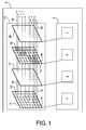
- the stereoscopic optical system 2 comprises a display or projector unit 10 of a single projector and a controller unit 8 for the system.
- the unit 10 comprises a first display panel 11 and a second display panel 14. Both panels are subdivided into individually addressable picture elements or pixels. This means that each pixel may change its state independently of the other pixels, i.e. an arbitrary image can be displayed using individually addressable pixels.
- the pixels of the first display can emit, transmit or reflect light when stimulated.
- the pixels of the second display can transmit or reflect light when stimulated.
- the controller unit 8 comprises a video controller 4 to control the image displayed on the first panel 11 and a polarisation controller 6 to control the second panel 14.
- the first display panel 11 comprises light emitting pixels, as exemplified by reference numerals 12 and 13.
- the light emitting pixels 12, 13 can emit light by modifying light from a light source, e.g. by alteration of their transmissivity, may be light source themselves or may be light reflecting elements. Examples for suitable light emitting pixels include, but are not limited to, light emitting diodes (LED), organic light emitting diodes (OLED), liquid crystal displays (LCD), digital micromirror devices (DMD) or liquid crystal on silicon (LCoS) devices.
- the light emitting pixels may comprise subpixels such as red, green and blue subpixels in order to generate light of a desired colour.
- a first spectral filter e.g. a first color selective retarder 17 is located.
- a spectral filter filters a parameter of the light passing through in a colour-selective manner, either in transmittance or in reflectance.
- a polarizer 20 is located in the path of the light leaving the second display panel 14 . This polarizer serves to selectively impede the transmission of light with a certain polarization state.
- a parameter of the light in a colour selective manner is meant any suitable optical filtering procedure which changes a parameter, such as amplitude, frequency or polarization, of the light in a colour selective manner.
- colour selective filtering To “filter the amplitude of the light in a colour selective manner” is typically known as colour selective filtering.
- a filter transmits some wavelengths or wavelength bands of light impinging onto it, and filters out, by reflection and/or absorption, other wavelengths or wavelength bands of light.
- This type of filter includes optical low pass filters, optical high pass filters or optical band pass filters.
- a colour selective retarder To “filter the polarization of the light in a colour selective manner” is typically performed by a colour selective retarder. Such a filter changes the polarization state of the light within a certain wavelength band (or within certain wavelength bands), while it does not change the polarization state of the light outside this wavelength band (or outside these wavelength bands).
- a fluorescence filter comprises an active optical element in which light from a first wavelength or wavelength band is converted into light from a second wavelength or wavelength band.
- filters which filter a parameter of the light in a colour selective manner include, but are not limited to, colour selective filters, colour selective retarders and cholesteric filters.
- the second display panel 14 comprises light transmitting or reflecting pixels, as exemplified by reference numerals 15 and 16. Each light transmitting or reflecting pixel is adapted to change the polarization state of the light passing through as a response to a signal.
- the light transmitting or reflecting pixel 15 is addressed to set the polarization of the light according to a certain polarization. This is indicated by the hatching of pixel 15.
- Light transmitting or reflecting pixel 16 is addressed to set the polarization of the light to a different polarization state than the polarization state of pixel 15. This is also indicated by the hatching of pixel 16. With this configuration and in combination with appropriate eyewear light emerging from the light emitting pixels can be divided between the left and the right eye of the viewer.
- the polarized light beam 18 emitted from pixel 12 and light beam 19 emitted by pixel 13 pass through the first spectral filter 17 into transmitting or reflecting pixels 15 and 16, respectively and after passing through the polarizer 20 leave as light beams 18' and 19'.
- the combination of 17,14 and 20 can be considered to be a tunable spectral filter.
- the second display panel 14 is arranged so that the light emitted from a light emitting pixel may pass through a pre-determined light. transmitting or reflecting pixel. In simple cases, as shown in FIG. 1 , this may be achieved by aligning the panels 11 and 14 in the optical paths. However, it is also possible to modify the optical paths by lenses, mirrors and the like.
- the first display panel may be projected on the second display panel or one may use for instance a collimated light source to be able to put the groups of display panels close to each other.
- the left eye image and the right eye image of the stereoscopic image are displayed simultaneously or substantially simultaneously on the light emitting pixels of the first display 11.
- the information on how much light should reach each eye is transferred via the light transmitting or reflecting pixels of the second display panel 14.
- a stereoscopic image can be achieved.
- tunable spectral filters e.g. transmittance tunable spectral filters
- the number of tunable spectral filters depends on the configuration or the type of light valve that is considered. In case of a direct view screen this may be a single tunable spectral filter, in which all pixels of the second display panel (for instance, an ECB cell) may be aligned with the red, green and blue subpixels of the intensity panel. Also in case of a single chip digital micromirror device (DMD) projector technology one single tunable spectral filter may be sufficient.
- DMD digital micromirror device
- the passive eyewear comprises filters with spectral characteristics substantially similar to the characteristics of the tunable spectral filters then this configuration can be used to control the amount of pixel light that will enter the left and right eye, i.e. it is possible to display stereo images.
- first display panel is used for other purposes than to define the intensity and that the second display panel is used for other purposes than to define the polarization.
- the system according to the present invention eliminates the need for separate display panels for the left and the right eye images. Projectors can be built smaller and the energy consumption can be reduced. Furthermore, cheaper passive eyewear such as colour filters may be worn by the observer. The need for polarization based eyewear is optional or eliminated.
- the light transmitting or reflecting pixels 15, 16 of the second display panel 14 comprise polarization changing selected from the group comprising electrically controlled birefringence (ECB) cells, optically controlled bend (OCB) cells, vertically aligned nematic (VAN) cells, twisted nematic (TN) cells, pi-cells, ferroelectric cells, antiferroelectric cells and/or non-liquid crystal cells.
- ECB electrically controlled birefringence
- OOB optically controlled bend
- VAN vertically aligned nematic
- TN twisted nematic
- pi-cells ferroelectric cells
- ferroelectric cells antiferroelectric cells and/or non-liquid crystal cells
- ferroelectric cells antiferroelectric cells and/or non-liquid crystal cells.
- ECB cells While it is often preferred to use ECB cells, the choice of using other display cells than ECB cells may result from the necessary spectral behaviour. In some applications it may be necessary to use very broadband cells as for instance TN cells, in other applications it may be useful to use small band cells, as for instance an ECB, OCB or VAN cells.
- the liquid crystal molecules may be oriented differently, the driven and undriven state may also differ.
- the first spectral filter 17 includes a colour selective retarder.
- FIG. 2 shows, reading from top to bottom, the effect of combining a colour selective retarder, an ECB cell and a polarizer.
- Light is emitted from display panel 21 with the corresponding optical spectrum shown to the left.
- the light that is already polarized before reaching 22 passes through colour selective retarder 22 which changes the light polarization of certain spectral parts.
- colour selective retarder 22 In the spectrum to the left of colour selective retarder 22 the two different polarizations are indicated by s and p, but of course s and p can represent any (preferably substantially orthogonal) polarizations.
- the light then passes through ECB cell 23.
- the former polarizations s and p of the specified wavelength bands are changed into elliptical polarization states e1 and e2.
- elliptical polarization states are substantially orthogonal to each other.
- the spectrum to the left of ECB cell 23 shows how specified wavelength bands have been given the polarization states e1 and e2.
- the light passes through polarizer 24.
- the effect of polarizer 24 is to impede the transmission of light with the polarization state e2 to a specific degree and polarization state e1 to another specific degree. This is shown in the spectrum to the left of polarizer 24.
- the first spectral filter 17 comprises cholesteric filters.
- the system further comprises a second polarizer.
- the second polarizer is located in the light path after the first spectral filter.
- This system may also further comprise a second spectral filter, which is located in the light path after the first spectral filter. Then the second polarizer is located in the light path after the second spectral filter.
- the second spectral filter includes a colour selective retarder.
- FIG. 3 shows, reading from top to bottom, the effect of combining several colour selective retarders, an ECB cell and polarizers.
- Light is emitted from display panel 31 with the corresponding optical spectrum shown to the left.
- the light passes through first colour selective retarder 32 which changes the light polarization of certain spectral parts.
- first colour selective retarder 32 which changes the light polarization of certain spectral parts.
- s and p In the spectrum to the left of colour selective retarder 32 the two different polarizations are indicated by s and p, but of course s and p can represent any (preferably substantially orthogonal) polarizations.
- the light then passes through second colour selective retarder 33.
- the former frequency bands with polarization p now receive the polarization s.
- new frequency bands with polarization p are created, as shown in the spectrum to the left.
- the system according to the present invention may further comprise optical notch filters in the light path.
- optical notch filters may for instance use the configuration of FIG. 2 and use a number of optical notch filters (like interference filters) to create space between two adjacent spectral bands.
- the system further comprises a third display panel subdivided into individually addressable light transmitting or reflecting pixels arranged so that the light from the first polarizer may pass through a pre-determined light transmitting or reflecting pixel.
- each light transmitting or reflecting pixel is adapted to change the polarization state of the light passing through as a response to a signal addressing the light transmitting or reflecting pixel.
- the transmitting or reflecting pixels of the third display panel comprise polarization changing means selected from the group comprising electrically controlled birefringence cells, optically controlled bend cells, vertically aligned nematic cells, twisted nematic cells, pi-cells, ferroelectric cells, antiferroelectric cells and/or non-liquid crystal cells.
- the light transmitting or reflecting pixels of the third display panel may comprise ECB cells to control the polarization of the light.
- the passive eyewear for this configuration uses a combination of spectral filtering and polarization. For instance the eyewear can have glued on polarizers.
- FIG. 4 shows such a system.
- Light is emitted from display panel 41 with the corresponding optical spectrum shown to the left.
- the light passes through colour selective retarder 42 which changes the light polarization of certain spectral parts.
- the two different polarizations are indicated by s and p, but of course s and p can represent any (preferably substantially orthogonal) polarizations.
- the light then passes through ECB cell 43.
- the former polarizations s and p of the specified wavelength bands are changed into elliptical polarization states e1 and e2. These elliptical polarization states are substantially orthogonal to each other.
- the spectrum to the left of ECB cell 43 shows how specified wavelength bands have been given the polarization states e1 and e2.
- the light passes through polarizer 44.
- the effect of polarizer 44 is to selectively impede the transmission of light with the polarization state e2.
- the resulting spectrum to the left shows the polarization state after passing the polarizer.
- the light passes through ECB cell 45 which changes the polarization to state e4.
- Polarization state e4 is an elliptical polarization state which determines the transmission through the left and right eye glass of an appropriate viewing device worn by a person. With this system it is possible to display two different stereo images for two observers.
- An intensity I_outgoing defines the outgoing light of an image pixel.
- the signal S(x,y, ⁇ ,I) that will determine this outgoing intensity is a function of the two stereo signals for left eye S_l(x,y, ⁇ ,I) and the right eye S_r(x,y, ⁇ ,I).
- a second display panel is used to define the polarization P_outgoing of the outgoing light of an image pixel.
- the processing of the signals S_l(x,y, ⁇ ,I) and S_r(x,y, ⁇ ,I) is indicated by step 51.
- the signal P(x,y, ⁇ ,I) that will determine this outgoing polarization is a function of the two stereo signals for the left eye S_l(x,y, ⁇ ,I) and the right eye S_r(x,y, ⁇ ,I). This is also illustrated in FIG. 5 .
- the light of an image pixel is thus characterized by two quantities: its intensity I_outgoing and its polarization P_outgoing. If one were to consider a polarization based passive eyewear to view the stereoscopic image, the polarization transmitted by the left eye polarizer may be orthogonal to the polarization transmitted by the right eye polarizer.
- a parameter of the light is then filtered in a colour-selective manner before changing the degree of polarization according to polarization information P.
- this filtering is done in a wavelength band selective manner so that different wavelength bands are assigned a different polarization.
- the amplitude of the light is modulated in a polarization-selective manner.
- this is undertaken in a wavelength band selective manner so that different wavelength bands have different amplitudes.
- FIG. 6 shows a pixelated image of the run lights of an airport at night as seen by.
- the lights are depicted as black pixels.
- the nearby images for each eye will be different and the run lights in the left eye image 61 and the right eye image 62 correspond to physically distinct pixels on the screen image 63.
- the grey level of the night image projected by the same pixel for the second eye can be sent to a single eye (notwithstanding the grey level of the night image projected by the same pixel for the second eye).
- the changing of the degree of polarization of the light in step g. is undertaken using means selected from the group comprising electrically controlled birefringence cells, optically controlled bend cells, vertically aligned nematic cells, twisted nematic cells, pi-cells, ferroelectric cells, antiferroelectric cells and/or non-liquid crystal cells.
- electrically controlled birefringence cells EMB cell
- a good way to illustrate the principle of operation of this is by means of the Poincaré sphere representation as shown in FIG. 7 .
- the polarization of the light entering the glasses is somewhere between the driven polarization state and the not driven polarization state ( FIG. 7.3 ) and can be characterized by its orientation angle ⁇ (0 ⁇ ⁇ ⁇ )and its ellipticity ⁇ (- ⁇ /4 ⁇ ⁇ ⁇ ⁇ /4).
- T_left 1 / 2 ⁇ 1 + cos 2 ⁇ ⁇ _ 1
- T_right 1 / 2 ⁇ 1 + cos 2 ⁇ ⁇ _r
- the filtering of a parameter of the light in a colour-selective manner according to step f. is undertaken using a colour-selective retarder.
- the colour selective retarder changes the polarization in a wavelength selective manner.
- different wavelength bands are assigned a different polarization.
- the controller unit 8 can be adapted to control the system 2 and in particular the display unit 10 so that a left eye stereo video signal S_l assigned to an individual light emitting pixel is provided.
- This signal comprises information on the x-coordinate of the pixel, the y-coordinate of the pixel, the wavelength of the light emitted by the pixel and the intensity of the light emitted by the pixel.
- the controller unit 8 can be adapted to control the system 2 and in particular the display unit 10 so that a right eye stereo video signal S_r assigned to an individual light emitting pixel is provided.
- This signal comprises information on the x-coordinate of the pixel, the y-coordinate of the pixel, the wavelength of the light emitted by the pixel and the intensity of the light emitted by the pixel.
- the controller unit 8 can be adapted to control the system 2 and in particular the diaplay unit 10 so that the signals S_l and S_r are processed to yield an intensity information S comprising information on the intensity and the wavelength of light emitted from a pixel with x and y coordinates and so that the signals S_l and S_r are processed to yield a polarization information P comprising information on the polarization and the wavelength of light emitted from a pixel with x and y coordinates.
- the controller unit 8 can be adapted to control the system 2 and in particular the display unit 10 so that the image can be projected or displayed according to intensity information S on a first projection or display panel 11, so that a parameter of the light is filtered in a colour-selective manner (for example, via spectral filter 17), so that the degree of polarization of the light can be varied according to polarization information P on a second projection or display panel 14 and so that the amplitude of the light leaving the second projection or display panel 14 can be modulated in a polarization-selective manner (for example, via polarizer 20).
- the controller unit 8 may include one or more processing engines, e.g. a microprocessor such as an Intel Pentium microprocessor or an embedded processor, e.g. an ARM processor core as described in " ARM, System-on-chip architecture" by Steve Furber, Addison-Wiley, 2nd edition, 2000 , e.g. as a VLSI chip around an embedded microprocessor such as an ARM7TDMI core designed by ARM Ltd., UK which may be synthesized onto a single chip.
- a processing engine may be a programmable digital logic device such as a Programmable Array Logic (PAL), a Programmable Logic Array, a Programmable Gate Array, especially a Field Programmable Gate Array (FPGA) or any other similar processing engine.
- the video controller 4, and the polarisation controller 6 may be implemented as separate units or may be all integrated into a single unit.
- the controller unit 8 may be an integral part of the display or projection system 2 or may be provided as a separate unit.
- the present invention also includes software for performing any of the methods of the present invention.
- the present invention provides software having code segments for implementing, when executed on a computing system control of a stereoscopic projection or display system to carry out a method according to the present invention.
- the software can include code segments for controlling the system so that a left eye stereo video signal S_l assigned to an individual light emitting pixel is provided, the signal comprising information on the x-coordinate of the pixel, the y-coordinate of the pixel, the wavelength of the light emitted by the pixel and the intensity of the light emitted by the pixel.
- the software can include code segments for controlling the system so that a right eye stereo video signal S_r assigned to an individual light emitting pixel is provided, the signal comprising information on the x-coordinate of the pixel, the y-coordinate of the pixel, the wavelength of the light emitted by the pixel and the intensity of the light emitted by the pixel.
- Additional code segments included in the software may control the system so that the signals S_l and S_r are processed to yield an intensity information S comprising information on the intensity and the wavelength of light emitted from a pixel with x and y coordinates and so that the signals S_l and S_r are processed to yield a polarization information P comprising information on the polarization and the wavelength of light emitted from a pixel with x and y coordinates.
- code segments included in the software may control the system so that the image can be projected or displayed according to intensity information S on a first projection or display panel, so that a parameter of the light is filtered in a colour-selective manner, so that the degree of polarization of the light can be varied according to polarization information P on a second projection or display panel and so that the amplitude of the light leaving the second projection or display panel can be modulated in a polarization-selective manner.
- the present invention is also directed towards a computer-readable medium, comprising the software or computer program product described above.
- the computer-readable medium stores instructions enabling a computer to carry out the method according to the present invention.
- Such media may be mass storage media, e.g. optical disk, magnetic storage such as a hardrive or diskettes or a tape drive, solid state memory such as a USB memory stick, random access memory or media accessible via a computer network, etc.
- a further aspect of the present invention relates to a stereoscopic optical system comprising a first cholesteric display and a second cholesteric display, wherein the first cholesteric display determines a first eye image and the second cholesteric display defines a second eye image and wherein the first cholesteric display and the second cholesteric display reflect circular polarized light of opposing handedness.
- first and the second cholesteric display each comprise red, green and blue pixels.
- a first cholesteric display comprising R, G and B subpixels for each pixel may determine the left eye image by defining the amount of left hand circular polarized in a certain image pixel. For a pixel in the non switched state all left handed circular polarized light is reflected, in the switched state all left handed circular polarized light is transmitted.
- a second cholesteric display comprising R, G and B subpixels for each pixel may determine the right eye image by defining the amount of right hand circular polarized in a certain image pixel. For a pixel in the non switched state all right handed circular polarized light is reflected, in the switched state all right handed circular polarized light is transmitted.
- the amount of outgoing left handed circular polarized light and the amount of outgoing right handed circular polarized light can be controlled. If the switching speed of the cholesteric displays is large enough, it is possible to replace the group (R, G, B) of displays by one display and use one of the existing colour sequential approaches. For this fourth embodiment one can use passive eyewear with circular polarizers. A possible advantage of this configuration is that the pixels of the two cholesteric displays do not have to be aligned very meticulously.
- a stereoscopic optical system comprising a display panel and in the optical path of the light of the display panel a first and a second cholesteric filter, the cholesteric filters comprising individually addressable pixels, wherein the light source is adapted to simultaneously display a left eye image and a right eye image, wherein the light from each pixel of the light source passes through a pre-determined pixel of the first and the second cholesteric filter and wherein the first and the second cholesteric filter reflect circular polarized light of opposing handedness.
- the number of cholesteric filters that is necessary depends on the display configuration that is considered. For a single chip DMD projector technology or for a direct view monitor for instance, one left handed cholesteric filter and one right handed cholesteric filter may be sufficient. For a 3 chip DMD projector technology or a 3 chip LCoS projector technology it may be necessary to use 3 left handed cholesteric filters and three right-handed cholesteric filters. However in such case the cholesteric filters may be small band, since it may be sufficient that they work in the red, green and blue wavelength region.
- the light beam 81 coming from a light emitting pixel reaches switchable cholesteric filter 82 of a first handedness.
- this filter defines the amount of left hand circular polarized light from a certain image pixel for the left eye.
- Cholesteric filter 82 reflects a certain amount of light 86 with the opposing circular polarization.
- the passing light 83 reaches cholesteric filter 84 of a second handedness.
- this filter defines the amount of right hand circular polarized light from a certain image pixel for the right eye.
- Cholesteric filter 84 reflects a certain amount of light 87 with the opposing circular polarization.
- the passing light 85 with a modulated circular polarization then reaches the viewer.
Landscapes
- Engineering & Computer Science (AREA)
- Multimedia (AREA)
- Signal Processing (AREA)
- Physics & Mathematics (AREA)
- General Physics & Mathematics (AREA)
- Optics & Photonics (AREA)
- Testing, Inspecting, Measuring Of Stereoscopic Televisions And Televisions (AREA)
Priority Applications (1)
| Application Number | Priority Date | Filing Date | Title |
|---|---|---|---|
| EP08160665A EP2146237A1 (fr) | 2008-07-17 | 2008-07-17 | Système optique stéréoscopique doté d'un seul projecteur avec des valves ultra légères dans le chemin lumineux |
Applications Claiming Priority (1)
| Application Number | Priority Date | Filing Date | Title |
|---|---|---|---|
| EP08160665A EP2146237A1 (fr) | 2008-07-17 | 2008-07-17 | Système optique stéréoscopique doté d'un seul projecteur avec des valves ultra légères dans le chemin lumineux |
Publications (1)
| Publication Number | Publication Date |
|---|---|
| EP2146237A1 true EP2146237A1 (fr) | 2010-01-20 |
Family
ID=39773179
Family Applications (1)
| Application Number | Title | Priority Date | Filing Date |
|---|---|---|---|
| EP08160665A Withdrawn EP2146237A1 (fr) | 2008-07-17 | 2008-07-17 | Système optique stéréoscopique doté d'un seul projecteur avec des valves ultra légères dans le chemin lumineux |
Country Status (1)
| Country | Link |
|---|---|
| EP (1) | EP2146237A1 (fr) |
Cited By (4)
| Publication number | Priority date | Publication date | Assignee | Title |
|---|---|---|---|---|
| CN101907801A (zh) * | 2010-07-23 | 2010-12-08 | 上海交通大学 | 基于可调光学滤波器的平板显示器 |
| CN102193239A (zh) * | 2010-03-08 | 2011-09-21 | 乐金显示有限公司 | 立体图像显示器及其驱动方法 |
| CN113917699A (zh) * | 2021-11-02 | 2022-01-11 | 合肥京东方卓印科技有限公司 | 三维显示面板及其控制方法和三维显示装置 |
| CN114128257B (zh) * | 2019-06-21 | 2024-05-07 | Pcms控股公司 | 用于基于角度滤波增强自动立体3d显示器的图像的方法 |
Citations (7)
| Publication number | Priority date | Publication date | Assignee | Title |
|---|---|---|---|---|
| WO1998025414A1 (fr) | 1996-12-06 | 1998-06-11 | The Rowland Institute For Science | Affichage stereoscopique electronique |
| US5835166A (en) * | 1994-08-17 | 1998-11-10 | Hall; Dennis R. | Chiral nematic liquid crystal polarization modulated color display for stereoscopic viewing device |
| US6188460B1 (en) * | 1990-06-11 | 2001-02-13 | Reveo, Inc. | Image display panel having a backlighting structure and a single-layer pixelated aray of reflective-type spectral filtering elements where between light is recycled for producing color images with enhanced brightness |
| US6580482B1 (en) * | 1998-11-11 | 2003-06-17 | Fuji Xerox Co., Ltd. | Multi-color display device |
| WO2004006005A1 (fr) * | 2002-07-08 | 2004-01-15 | Koninklijke Philips Electronics N.V. | Afficheur stereoscopique reflectif |
| WO2006038819A1 (fr) | 2004-10-01 | 2006-04-13 | Pure Depth Limited | Affichage stereoscopique ameliore |
| EP1830585A2 (fr) | 2003-10-21 | 2007-09-05 | Barco N.V. | Procédé et dispositif pour effectuer un affichage d'image stéréoscopique basé sur des filtres de sélection de couleur |
-
2008
- 2008-07-17 EP EP08160665A patent/EP2146237A1/fr not_active Withdrawn
Patent Citations (7)
| Publication number | Priority date | Publication date | Assignee | Title |
|---|---|---|---|---|
| US6188460B1 (en) * | 1990-06-11 | 2001-02-13 | Reveo, Inc. | Image display panel having a backlighting structure and a single-layer pixelated aray of reflective-type spectral filtering elements where between light is recycled for producing color images with enhanced brightness |
| US5835166A (en) * | 1994-08-17 | 1998-11-10 | Hall; Dennis R. | Chiral nematic liquid crystal polarization modulated color display for stereoscopic viewing device |
| WO1998025414A1 (fr) | 1996-12-06 | 1998-06-11 | The Rowland Institute For Science | Affichage stereoscopique electronique |
| US6580482B1 (en) * | 1998-11-11 | 2003-06-17 | Fuji Xerox Co., Ltd. | Multi-color display device |
| WO2004006005A1 (fr) * | 2002-07-08 | 2004-01-15 | Koninklijke Philips Electronics N.V. | Afficheur stereoscopique reflectif |
| EP1830585A2 (fr) | 2003-10-21 | 2007-09-05 | Barco N.V. | Procédé et dispositif pour effectuer un affichage d'image stéréoscopique basé sur des filtres de sélection de couleur |
| WO2006038819A1 (fr) | 2004-10-01 | 2006-04-13 | Pure Depth Limited | Affichage stereoscopique ameliore |
Non-Patent Citations (1)
| Title |
|---|
| STEVE FURBER: "ARM, System-on-chip architecture", 2000, ADDISON-WILEY |
Cited By (8)
| Publication number | Priority date | Publication date | Assignee | Title |
|---|---|---|---|---|
| CN102193239A (zh) * | 2010-03-08 | 2011-09-21 | 乐金显示有限公司 | 立体图像显示器及其驱动方法 |
| CN102193239B (zh) * | 2010-03-08 | 2014-03-19 | 乐金显示有限公司 | 立体图像显示器及其驱动方法 |
| CN101907801A (zh) * | 2010-07-23 | 2010-12-08 | 上海交通大学 | 基于可调光学滤波器的平板显示器 |
| CN101907801B (zh) * | 2010-07-23 | 2013-11-27 | 上海交通大学 | 基于可调光学滤波器的平板显示器 |
| CN114128257B (zh) * | 2019-06-21 | 2024-05-07 | Pcms控股公司 | 用于基于角度滤波增强自动立体3d显示器的图像的方法 |
| US12147057B2 (en) | 2019-06-21 | 2024-11-19 | Interdigital Madison Patent Holdings, Sas | Method for enhancing the image of autostereoscopic 3D displays based on angular filtering |
| CN113917699A (zh) * | 2021-11-02 | 2022-01-11 | 合肥京东方卓印科技有限公司 | 三维显示面板及其控制方法和三维显示装置 |
| CN113917699B (zh) * | 2021-11-02 | 2024-01-05 | 合肥京东方卓印科技有限公司 | 三维显示面板及其控制方法和三维显示装置 |
Similar Documents
| Publication | Publication Date | Title |
|---|---|---|
| Zhan et al. | Multifocal displays: review and prospect | |
| CN111587393B (zh) | 用于遮挡功能的紧凑显示器的方法和系统 | |
| US9946070B2 (en) | Automotive head up display | |
| US11022803B2 (en) | Eye glasses-type transparent display using mirror | |
| JP5033264B2 (ja) | 立体画像表示装置および立体画像表示方法 | |
| JP3565391B2 (ja) | 視点補正自動立体表示装置 | |
| TWI615634B (zh) | 透明自動立體顯示器 | |
| EP0721132B1 (fr) | Dispositif d'affichage autostéréoscopique | |
| CN100591141C (zh) | 透镜阵列结构和显示设备 | |
| JPH08248355A (ja) | 三次元ディスプレイ | |
| CN101840073A (zh) | 二维和三维可切换的多个全尺寸图像的图像显示系统 | |
| WO2011043100A1 (fr) | Écran, système d'affichage, terminal portable et dispositif électronique | |
| CN102985869B (zh) | 立体显示光源模块、立体显示成像装置和立体显示系统 | |
| EP2146237A1 (fr) | Système optique stéréoscopique doté d'un seul projecteur avec des valves ultra légères dans le chemin lumineux | |
| KR20090100361A (ko) | 교대로 편광하기 위한 회전 반투명 실린더를 갖는 2d/3d 프로젝터 | |
| US9013563B2 (en) | Wavelength separation device, projector, and image display system | |
| US9420274B2 (en) | Stereoscopic image system and related driving method for balancing brightness of left-eye and right-eye images | |
| CN102854631A (zh) | 立体影像显示设备以及其形成方法 | |
| KR101862073B1 (ko) | 삼차원 영상 표시장치 및 편광안경, 그리고 삼차원 영상 구현시스템 | |
| KR101978787B1 (ko) | 입체 영상 표시장치 | |
| CN102890363B (zh) | 液晶显示设备及立体影像显示设备 | |
| KR20090083840A (ko) | 입체 화상 시스템 | |
| JP5539746B2 (ja) | 立体画像表示装置 | |
| Zhang et al. | A novel spatio-temporal multiplexing multi-view 3D display | |
| JP2014126757A (ja) | スクリーンおよび画像表示システム |
Legal Events
| Date | Code | Title | Description |
|---|---|---|---|
| PUAI | Public reference made under article 153(3) epc to a published international application that has entered the european phase |
Free format text: ORIGINAL CODE: 0009012 |
|
| AK | Designated contracting states |
Kind code of ref document: A1 Designated state(s): AT BE BG CH CY CZ DE DK EE ES FI FR GB GR HR HU IE IS IT LI LT LU LV MC MT NL NO PL PT RO SE SI SK TR |
|
| AX | Request for extension of the european patent |
Extension state: AL BA MK RS |
|
| AKY | No designation fees paid | ||
| REG | Reference to a national code |
Ref country code: DE Ref legal event code: 8566 |
|
| STAA | Information on the status of an ep patent application or granted ep patent |
Free format text: STATUS: THE APPLICATION IS DEEMED TO BE WITHDRAWN |
|
| 18D | Application deemed to be withdrawn |
Effective date: 20100721 |