EP2146362A1 - Durch Drehelemente betätigte Endschaltervorrichtung - Google Patents
Durch Drehelemente betätigte Endschaltervorrichtung Download PDFInfo
- Publication number
- EP2146362A1 EP2146362A1 EP08252426A EP08252426A EP2146362A1 EP 2146362 A1 EP2146362 A1 EP 2146362A1 EP 08252426 A EP08252426 A EP 08252426A EP 08252426 A EP08252426 A EP 08252426A EP 2146362 A1 EP2146362 A1 EP 2146362A1
- Authority
- EP
- European Patent Office
- Prior art keywords
- sleeve
- screws
- travelling
- abutment
- cheek
- Prior art date
- Legal status (The legal status is an assumption and is not a legal conclusion. Google has not performed a legal analysis and makes no representation as to the accuracy of the status listed.)
- Withdrawn
Links
- 238000004804 winding Methods 0.000 claims abstract description 17
- 230000000295 complement effect Effects 0.000 claims description 7
- 230000005540 biological transmission Effects 0.000 claims description 6
- 230000002441 reversible effect Effects 0.000 claims description 3
- 238000007792 addition Methods 0.000 description 1
- 238000004519 manufacturing process Methods 0.000 description 1
- 238000012986 modification Methods 0.000 description 1
- 230000004048 modification Effects 0.000 description 1
- 238000003466 welding Methods 0.000 description 1
Images
Classifications
-
- H—ELECTRICITY
- H01—ELECTRIC ELEMENTS
- H01H—ELECTRIC SWITCHES; RELAYS; SELECTORS; EMERGENCY PROTECTIVE DEVICES
- H01H19/00—Switches operated by an operating part which is rotatable about a longitudinal axis thereof and which is acted upon directly by a solid body external to the switch, e.g. by a hand
- H01H19/02—Details
- H01H19/10—Movable parts; Contacts mounted thereon
- H01H19/14—Operating parts, e.g. turn knob
- H01H19/18—Operating parts, e.g. turn knob adapted for actuation at a limit or other predetermined position in the path of a body, the relative movement of switch and body being primarily for a purpose other than the actuation of the switch, e.g. door switch, limit switch, floor-levelling switch of a lift
- H01H19/186—Operating parts, e.g. turn knob adapted for actuation at a limit or other predetermined position in the path of a body, the relative movement of switch and body being primarily for a purpose other than the actuation of the switch, e.g. door switch, limit switch, floor-levelling switch of a lift with travelling nuts
Definitions
- the present invention relates generally to an electrical switching device, and, more particularly, to such a switching device which is actuated by rotary elements.
- a limit switch device comprising:
- the device further includes:
- the reduction gear set includes a second gear supported on an axle mounted to the cheek and meshed internally with the ring gear, a third gear rotationally fast with the second gear and meshed internally of a fourth gear rotationally fast with the sleeve.
- first and second travelling screws each have a longitudinally extending threaded aperture therein and the first and second abutments have complementary threaded portions engaged therein for adjusting the abutments longitudinally.
- the guide means comprises a pair of parallel rods fixed at one longitudinal end to the cheek and received in diametrically opposite apertures in each of the first and second travelling screws.
- each abutment is adjustable longitudinally relative to the travelling screw to which it is mounted.
- each abutment comprises a screw threaded shaft portion in a threaded aperture in a respective one of the travelling screws such that the position of the abutment is adjusted by rotation of the threaded shaft.
- the device further includes a pair of adjuster members each mounted to rotate about a transverse axis, each adjuster member having means for engaging a tool and transmission means for transmitting torque between adjuster and its respective abutment.
- the transmission means includes a worm coaxial with the adjuster member and meshed with a worm wheel mounted to the abutment shaft.
- the invention provides a limit switch device comprising:
- the invention provides a winding device comprising:
- This invention provides a limit switch device which is effective and efficient in operational use, and which is compact in both the longitudinal and radial dimensions.
- the device may be economically constructed and has an overall simple design which minimizes manufacturing gear costs.
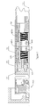
- Fig. 1 shows a tubular motor winding device comprising a winding tube 11 on which is wound a roller blind, or the like (not shown).
- This winding tube 11 has a central longitudinal axis 71 and one end of the winding tube 11 engages the limit switch device 10.
- Fixed to a longitudinal end of the limit switch device 10 is a support assembly 70 which may be mounted, for example, in a window opening.
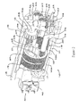
- first cheek 12 and a second cheek 13 Fixed together by a pair of parallel guide rods 54.
- the cheeks 12, 13 are fixed via intermediate members to the frame of a window, or the like.
- a journal block 14 is fixed to the first cheek 12 and cooperates with the cheek 12 to locate and support a ring gear 15 for rotation about the axis 71.
- the ring gear 15 is journaled on coaxial cylindrical faces on the journal block 14 and cheek 12 and located axially between shoulders on the journal block 14 and cheek 12.
- a generally cylindrical sleeve 16 is supported to rotate about the axis 71 with its opposing ends received in coaxial recesses in the second cheek 13 and the journal block 14.
- On the inside of the sleeve 16 are screw threaded portions of opposite hand, a left handed portion 17 innermost and a right handed portion 18 outermost.
- the screw threaded portions 17, 18 are aligned coaxially and are of the same nominal diameter and pitch. As illustrated, the screw threaded portions 17, 18 may be formed on separate portions 16a, 16b permanently joined as by an interference fit or welding to form the sleeve 16.
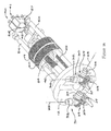
- First and second travelling screws 19, 20 have external left and right handed threads and are received in the left and right handed screw threaded portions 17, 18 respectively.
- a pair of parallel axially extending apertures 21, 22 are provided in each of the travelling screws 19, 20, in diametrically opposing positions.
- a threaded hole 23, aligned axially, is also formed in each of the travelling screws 19, 20.
- the guide rods 54 extend axially and are received in the apertures 21, 22 in both traveling screws 19, 20 in a sliding fit thereby preventing rotation of the traveling screws which are thereby guided linearly.
- First and second abutments or abutment shafts 24, 25 are elongated to extend axially and each is externally threaded and received in one of the threaded holes 23 in each of the travelling screws 19, 20.
- the abutment shafts 24, 25 protrude from the traveling screws 19, 20 and their inner ends terminate in inner faces 26, 27.
- the longitudinally opposing outer ends of the abutment shafts 24, 25 extend through the cheek where each is supported in a worm wheel mounted to the cheek, securing gear the worm wheel axially relative to the abutment shaft 24, 25.
- each abutment shaft 24, 25 has a longitudinally extending flat 28 and is received in a through-extending aperture in the helicoids gear or worm wheel 29 which is of complementary shape to the abutment shaft 24, 25, with a corresponding flat such that torque can be transmitted between the worm wheel 29 and abutment shaft 24, 25, while the abutment shaft 24, 25 can also slide longitudinally within the worm wheel.
- Two adjuster members 30, 31 are mounted to the cheek 12 such that each may rotate about transversely aligned first parallel axes 35, 36.
- Each adjuster member 30, 31 has a first socket 32 for receiving a tool, and an integral worm gear 33 meshed with the worm wheel 29.
- the sockets 32 are recessed within the cheek 12.
- second sockets 34 are mounted for rotation about parallel transverse axes 37, 38 substantially orthogonal to the first axes 35, 36.
- a bevel gear pair 39 connects each second socket 34 and adjuster member 30, 31 for transmitting torque therebetween.
- a pair of electrical limit switches 40, 41 are co-located at one longitudinal end of the limit switch device 10.
- the switches are mounted to the second cheek 13 adjacent one another.
- Each switch 40, 41 has an actuator 42 by which the switch is actuated, the actuators 42 being aligned axially with the end faces 26, 27 of the abutment shafts 24, 25.
- the switches 40, 41 are connected to a controller (not shown) for controlling power supply to the reversible motor for moving the blind.
- the controller prevents the motor being driven in a first direction to raise the blind when switch 40 is actuated, and correspondingly prevents the motor being driven in a second direction, opposite the first direction, to lower the blind when switch 41 is actuated.
- a reduction gear set includes a second spur gear 45 supported on an axle 46 integral with the first cheek 12 and meshed internally with the teeth 44 of first ring gear.
- a third spur gear 47 rotationally fast with the second gear 45 is sized to provide a second reduction stage.
- a third reduction stage is provided by the third gear 47 being meshed internally with a fourth ring gear 48, the teeth of which are formed internally in the sleeve 16.
- the winding tube 11 is rotationally fast with the ring gear 15 and thus operation of the motor to rotate the winding tube 11 drive the travelling screws 19, 20 to reciprocate linearly, in opposite directions.
- the reduction gear set provides a large reduction in a small space, thereby allowing the axial dimension of the device to be reduced, while the coaxial arrangement of the traveling screws allows a reduction in the radial dimension of the device.
Landscapes
- Operating, Guiding And Securing Of Roll- Type Closing Members (AREA)
- Transmission Devices (AREA)
Priority Applications (1)
| Application Number | Priority Date | Filing Date | Title |
|---|---|---|---|
| EP08252426A EP2146362A1 (de) | 2008-07-17 | 2008-07-17 | Durch Drehelemente betätigte Endschaltervorrichtung |
Applications Claiming Priority (1)
| Application Number | Priority Date | Filing Date | Title |
|---|---|---|---|
| EP08252426A EP2146362A1 (de) | 2008-07-17 | 2008-07-17 | Durch Drehelemente betätigte Endschaltervorrichtung |
Publications (1)
| Publication Number | Publication Date |
|---|---|
| EP2146362A1 true EP2146362A1 (de) | 2010-01-20 |
Family
ID=40011039
Family Applications (1)
| Application Number | Title | Priority Date | Filing Date |
|---|---|---|---|
| EP08252426A Withdrawn EP2146362A1 (de) | 2008-07-17 | 2008-07-17 | Durch Drehelemente betätigte Endschaltervorrichtung |
Country Status (1)
| Country | Link |
|---|---|
| EP (1) | EP2146362A1 (de) |
Citations (2)
| Publication number | Priority date | Publication date | Assignee | Title |
|---|---|---|---|---|
| GB698642A (en) * | 1951-05-28 | 1953-10-21 | Henry Hope & Sons Ltd | Electric limit switches |
| US5111925A (en) * | 1989-12-22 | 1992-05-12 | Somfy | Device for automatically halting an electric motor after a certain number of revolutions |
-
2008
- 2008-07-17 EP EP08252426A patent/EP2146362A1/de not_active Withdrawn
Patent Citations (2)
| Publication number | Priority date | Publication date | Assignee | Title |
|---|---|---|---|---|
| GB698642A (en) * | 1951-05-28 | 1953-10-21 | Henry Hope & Sons Ltd | Electric limit switches |
| US5111925A (en) * | 1989-12-22 | 1992-05-12 | Somfy | Device for automatically halting an electric motor after a certain number of revolutions |
Similar Documents
| Publication | Publication Date | Title |
|---|---|---|
| EP2454434B1 (de) | Antriebseinrichtung eines fahrzeug-bauteils, insbesondere einer karosserieklappe | |
| EP1898042B1 (de) | Rohrförmige Antriebsvorrichtung zum Auf- und Abwickeln einer Verdunkelungsvorrichtung, insbesondere eines Rollladens oder dergleichen | |
| EP2964508B1 (de) | Begrenzungseinrichtung für die lenkwinkeleingabe in einer elektrischen lenkung | |
| EP3700799A1 (de) | Lenksäule für ein kraftfahrzeug | |
| EP4054918B1 (de) | Feedback-aktuator für eine lenkeinrichtung eines kraftfahrzeugs | |
| EP1233690A1 (de) | Elektromotorischer stellantrieb | |
| WO2020120055A1 (de) | Türantriebsvorrichtung | |
| EP3077665B1 (de) | Elektrische schmierstoffpumpe mit zuschaltbarem mechanischem antrieb | |
| DE10200169A1 (de) | Möbelantrieb zum Verstellen von Teilen eines Möbels relativ zueinander | |
| DE20311032U1 (de) | Antriebsvorrichtung | |
| EP1118741A2 (de) | Kraftübertragungsvorrichtung mit wälzgelagerter Schrauben/Muttereinheit sowie ein mit dieser Vorrichtung versehener Linearantrieb | |
| EP2146362A1 (de) | Durch Drehelemente betätigte Endschaltervorrichtung | |
| EP2675045A2 (de) | Verstellvorrichtung | |
| DE102021119535B3 (de) | Chirurgisches Instrument mit Hub-Dreh-Getriebe | |
| EP1870617A2 (de) | Betätigungseinrichtung für ein Getriebe eines Fahrzeugs | |
| DE202008013947U1 (de) | Elektromotor | |
| DE3608988A1 (de) | Vorrichtung zur handbetaetigung einer elektromotorisch antreibbaren wickelwelle z.b. eines rolladens | |
| EP4185510B1 (de) | Feedback-aktuator für eine lenkeinrichtung eines kraftfahrzeugs und lenksäule für ein kraftfahrzeug | |
| EP2186984A1 (de) | Antriebselement für eine Tür | |
| EP3673132A1 (de) | Linearantrieb mit rückensteifer kette | |
| EP2675044A2 (de) | Verstellvorrichtung | |
| WO2018197134A1 (de) | Wankstabilisator sowie verwendung eines wankstabilisators in einem kraftfahrzeug | |
| EP2607605B1 (de) | Rollladenzugantrieb | |
| WO2017042021A1 (de) | Nutzfahrzeuglenkung | |
| DE102006041689A1 (de) | Rohrförmige Antriebsvorrichtung zum Auf- und Abwickeln einer Verdunkelungsvorrichtung, insbesondere eines Rollladens o.dgl. |
Legal Events
| Date | Code | Title | Description |
|---|---|---|---|
| PUAI | Public reference made under article 153(3) epc to a published international application that has entered the european phase |
Free format text: ORIGINAL CODE: 0009012 |
|
| AK | Designated contracting states |
Kind code of ref document: A1 Designated state(s): AT BE BG CH CY CZ DE DK EE ES FI FR GB GR HR HU IE IS IT LI LT LU LV MC MT NL NO PL PT RO SE SI SK TR |
|
| AX | Request for extension of the european patent |
Extension state: AL BA MK RS |
|
| 17P | Request for examination filed |
Effective date: 20100716 |
|
| AKX | Designation fees paid |
Designated state(s): AT BE BG CH CY CZ DE DK EE ES FI FR GB GR HR HU IE IS IT LI LT LU LV MC MT NL NO PL PT RO SE SI SK TR |
|
| RAP1 | Party data changed (applicant data changed or rights of an application transferred) |
Owner name: NORTUS INTERNATIONAL LIMITED |
|
| GRAP | Despatch of communication of intention to grant a patent |
Free format text: ORIGINAL CODE: EPIDOSNIGR1 |
|
| STAA | Information on the status of an ep patent application or granted ep patent |
Free format text: STATUS: THE APPLICATION IS DEEMED TO BE WITHDRAWN |
|
| 18D | Application deemed to be withdrawn |
Effective date: 20110823 |