EP2146406A2 - Agencement optique et procédé - Google Patents
Agencement optique et procédé Download PDFInfo
- Publication number
- EP2146406A2 EP2146406A2 EP09158492A EP09158492A EP2146406A2 EP 2146406 A2 EP2146406 A2 EP 2146406A2 EP 09158492 A EP09158492 A EP 09158492A EP 09158492 A EP09158492 A EP 09158492A EP 2146406 A2 EP2146406 A2 EP 2146406A2
- Authority
- EP
- European Patent Office
- Prior art keywords
- cavity
- electromagnetic radiation
- arrangement
- incoherent
- intra
- Prior art date
- Legal status (The legal status is an assumption and is not a legal conclusion. Google has not performed a legal analysis and makes no representation as to the accuracy of the status listed.)
- Withdrawn
Links
- 238000000034 method Methods 0.000 title claims description 19
- 230000003287 optical effect Effects 0.000 title description 5
- 239000013078 crystal Substances 0.000 claims abstract description 55
- 230000005670 electromagnetic radiation Effects 0.000 claims abstract description 47
- 230000005855 radiation Effects 0.000 claims abstract description 30
- 230000003993 interaction Effects 0.000 claims abstract description 15
- 238000006243 chemical reaction Methods 0.000 claims description 14
- 239000000835 fiber Substances 0.000 claims description 7
- 239000000523 sample Substances 0.000 claims description 6
- 238000005086 pumping Methods 0.000 claims description 3
- 238000003384 imaging method Methods 0.000 abstract description 6
- 230000005540 biological transmission Effects 0.000 description 6
- 238000010586 diagram Methods 0.000 description 6
- 230000008569 process Effects 0.000 description 6
- 230000003595 spectral effect Effects 0.000 description 6
- 230000035945 sensitivity Effects 0.000 description 5
- 238000000576 coating method Methods 0.000 description 4
- 238000001914 filtration Methods 0.000 description 4
- 238000004476 mid-IR spectroscopy Methods 0.000 description 4
- 239000007787 solid Substances 0.000 description 4
- 238000001228 spectrum Methods 0.000 description 4
- 238000009795 derivation Methods 0.000 description 3
- 230000005684 electric field Effects 0.000 description 3
- 238000005286 illumination Methods 0.000 description 3
- 229910003327 LiNbO3 Inorganic materials 0.000 description 2
- 201000009310 astigmatism Diseases 0.000 description 2
- 230000015572 biosynthetic process Effects 0.000 description 2
- 230000001427 coherent effect Effects 0.000 description 2
- 230000008878 coupling Effects 0.000 description 2
- 238000010168 coupling process Methods 0.000 description 2
- 238000005859 coupling reaction Methods 0.000 description 2
- 230000000694 effects Effects 0.000 description 2
- 239000007789 gas Substances 0.000 description 2
- 239000000463 material Substances 0.000 description 2
- 230000010287 polarization Effects 0.000 description 2
- 229920006395 saturated elastomer Polymers 0.000 description 2
- 239000004065 semiconductor Substances 0.000 description 2
- 230000006641 stabilisation Effects 0.000 description 2
- 238000011105 stabilization Methods 0.000 description 2
- 230000001131 transforming effect Effects 0.000 description 2
- 230000000007 visual effect Effects 0.000 description 2
- 238000010521 absorption reaction Methods 0.000 description 1
- 230000009286 beneficial effect Effects 0.000 description 1
- 239000011248 coating agent Substances 0.000 description 1
- 230000001066 destructive effect Effects 0.000 description 1
- 238000001514 detection method Methods 0.000 description 1
- 230000003028 elevating effect Effects 0.000 description 1
- 238000005516 engineering process Methods 0.000 description 1
- 238000002474 experimental method Methods 0.000 description 1
- 239000007788 liquid Substances 0.000 description 1
- 238000004519 manufacturing process Methods 0.000 description 1
- 230000007246 mechanism Effects 0.000 description 1
- 230000035699 permeability Effects 0.000 description 1
- 230000009467 reduction Effects 0.000 description 1
- 238000005070 sampling Methods 0.000 description 1
- 229910052594 sapphire Inorganic materials 0.000 description 1
- 239000010980 sapphire Substances 0.000 description 1
- 238000000926 separation method Methods 0.000 description 1
- 230000009466 transformation Effects 0.000 description 1
- XLYOFNOQVPJJNP-UHFFFAOYSA-N water Chemical compound O XLYOFNOQVPJJNP-UHFFFAOYSA-N 0.000 description 1
Images


Classifications
-
- H—ELECTRICITY
- H01—ELECTRIC ELEMENTS
- H01S—DEVICES USING THE PROCESS OF LIGHT AMPLIFICATION BY STIMULATED EMISSION OF RADIATION [LASER] TO AMPLIFY OR GENERATE LIGHT; DEVICES USING STIMULATED EMISSION OF ELECTROMAGNETIC RADIATION IN WAVE RANGES OTHER THAN OPTICAL
- H01S3/00—Lasers, i.e. devices using stimulated emission of electromagnetic radiation in the infrared, visible or ultraviolet wave range
- H01S3/10—Controlling the intensity, frequency, phase, polarisation or direction of the emitted radiation, e.g. switching, gating, modulating or demodulating
- H01S3/106—Controlling the intensity, frequency, phase, polarisation or direction of the emitted radiation, e.g. switching, gating, modulating or demodulating by controlling devices placed within the cavity
- H01S3/108—Controlling the intensity, frequency, phase, polarisation or direction of the emitted radiation, e.g. switching, gating, modulating or demodulating by controlling devices placed within the cavity using non-linear optical devices, e.g. exhibiting Brillouin or Raman scattering
- H01S3/1083—Controlling the intensity, frequency, phase, polarisation or direction of the emitted radiation, e.g. switching, gating, modulating or demodulating by controlling devices placed within the cavity using non-linear optical devices, e.g. exhibiting Brillouin or Raman scattering using parametric generation
Definitions
- the present invention relates to the use of a laser to process incoherent light.
- the use of lasers for processing light includes conversion of light from one part of the electromagnetic spectrum to another part of the spectrum.
- processing involves the use of a nonlinear crystal in which an intensive laser beam interacts with an input laser beam, resulting in an output laser beam having a wavelength that is different from the intensive laser beam and the input beam.
- An example of a system in which such processing is performed is described in European patent published as EP0301803 .
- a drawback with such a prior art system is that it is incapable of processing of input light that is incoherent. For example, imaging of spatially extended sources that emit or reflect incoherent light is impossible in such a prior art system.
- an arrangement for processing incoming incoherent electromagnetic radiation said incoming incoherent electromagnetic radiation comprising radiation in a first wavelength interval.
- the arrangement comprises a focusing arrangement for focusing the incoming incoherent electromagnetic radiation, a first cavity configured to comprise an intra cavity laser beam, a nonlinear crystal arranged in the first cavity such that it is capable of receiving the focused incoherent electromagnetic radiation and, in dependence on the spatial overlap between the focused incoherent electromagnetic radiation and the intra-cavity laser beam, by interaction with the intra-cavity laser beam provide processed electromagnetic radiation, said processed electromagnetic radiation comprising radiation in a second wavelength interval.
- such an arrangement is capable of enabling imaging, e.g. by utilizing a detector that is sensitive in the second wavelength interval, a source of radiation that emits or reflects incoherent light in a first wavelength interval.
- Embodiments include those that comprise a scan unit configured such that it is capable of spatial scanning of incoherent light emanating from an extended light source and conveying the scanned incoherent light to the focusing arrangement.
- Embodiments incude those that comprise a single mode fibre probe and a lens for collecting incoherent light from inside an extended light source.
- the arrangement may be configured such that the first cavity is capable of receiving laser energy from a laser source operating in, e.g., a continuous wave mode or a pulsed mode, outside the first cavity.
- a laser source operating in, e.g., a continuous wave mode or a pulsed mode
- This configuration provides a possibility to generate a high intracavity field inside the first cavity at all frequencies supported by any laser media.
- the technique used is called "frequency locking" of a laser to an external cavity. Frequency locking often involves an electronic stabilization unit.
- Diode lasers are beneficial since they can be designed for operation at a specific wavelength within in a broad wavelength region. The wavelength flexibility can be used to facilitate a specific transformation between the first and second wavelength range.
- the arrangement may be configured such that the first cavity comprises a lasant medium and a pump source for pumping said lasant medium, the pump source operating in, e.g., a continuous wave mode or a pulsed mode.
- the lasant medium passively locks itself to the cavity which circumvent any need for active stabilization.
- the lasant medium may be of the type solid state, semiconductor, gas or liquid
- the pumping source may be a flash lamp, semiconductor laser, solid state laser, light emitting diode or current.
- the non-linear crystal may be phase matched to optimize the conversion of incoming electromagnetic radiation in a first wavelength interval to the processed radiation in the second wavelength interval.
- phase matching PM
- QPM quasi phase matching
- the nonlinear crystal may be configured to be tuned for obtaining phase matching. This can be accomplished using angle tuning of the nonlinear crystal, by applying temperature or pressure to crystal or through quasi phase matching.
- the nonlinear crystal may be configured to be poled for obtaining phase matching. This is method is referred to as quasi phase matching.
- quasi phase matching By (synthetically) changing the direction of the polarization of the dipole moment of the nonlinear crystal periodically, quasi phase matching can be obtained.
- the periodicity is specific to the interaction at hand.
- Two nonlinear crystals often used for quasi phase matching is PP KTP and PP LiNbO 3 ,
- the nonlinear crystal may be configured to be poled in a fanned or chirped manner.
- the fanning implies that the periodicity of the poled crystal is different at different transverse positions in the crystal.
- the poling may also include a chirped structure leading to broad spectral acceptance.
- the nonlinear crystal may be a Brewster cut. This is advantageous since it solves a practical problem that arises from the fact that three different wavelengths are involved, i.e. the wavelength of the incoming radiation, the wavelength of the intra cavity beam and the wavelength of the processed beam. It is difficult and expensive to manufacture dielectric coatings that can act as an antireflexion coating at all three wavelengths. However if the nonlinear crystal is Brewster cut, p-polarized will essentially be transmitted loss-less (or with very low loss), thereby elevating the need for coatings at the end surfaces. When using quasi phase matching all the three mentioned radiation fields can be p-polarized. Thus periodically poled crystals with Brewster cut ends are particularly advantageous.
- the arrangement may be configured such that the interaction between the incoming electromagnetic radiation and the intra cavity beam comprises any one of difference frequency generation, DFG, sum frequency generation, SFG and any combination thereof.
- SFG and DFG constitute the underlying physical mechanism that allows processing of incoming radiation as described herein.
- the shortest wavelength of the second wavelength interval may be shorter than the shortest wavelength of said first wavelength interval.
- the first wavelength interval may be an infrared wavelength interval and the second wavelength interval may be a visual wavelength interval, or the first wavelength interval may be a mid infrared wavelength interval and the second wavelength interval may be a near infrared wavelength interval.
- the longest wavelength of the second wavelength interval may be longer than the longest wavelength of said first wavelength interval.
- the first wavelength interval may be an ultraviolet wavelength interval and the second wavelength interval may be a visual wavelength interval.
- the first cavity may be a unidirectional ring cavity.
- the cavity which supports the intra cavity beam often comprises two or more mirrors aligned so as to form a standing wave cavity.
- a standing wave cavity is characterized by supporting a beam that propagates back and forth forming a standing wave.
- spatial hole burning occurs. Spatial hole burning leads to secondary lasing emission characterized by emitting new wavelengths. Due to a lack of good phase matching of this (or these) new secondary mode(s), the overall efficiency of the SFG or DFG of interaction is reduced.
- the unidirectional ring cavity support a traveling wave which does not lead to standing wave formation and thus spatial hole burning. The unidirectional ring cavity will thus be able to accommodate an intense intra cavity beam leading to high interaction efficiency.
- the first cavity may comprise a frequency selective element for narrowing the bandwidth of the intra cavity beam.
- This approach also has the purpose of reducing the formation of secondary lasing modes in a standing wave cavity.
- Typical frequency selective elements are etalons, Lyot filters, gratings and birefringent prism.
- a method for processing incoming incoherent electromagnetic radiation said incoming incoherent electromagnetic radiation comprising light in a first wavelength interval.
- the method comprises focusing the incoming incoherent electromagnetic radiation, maintaining an intracavity laser beam in a first cavity, receiving the focused incoherent electromagnetic radiation in a nonlinear crystal arranged in the first cavity and, in dependence on the spatial overlap between the focused incoherent electromagnetic radiation and the intra-cavity laser beam, by interaction with the intra-cavity laser beam providing a processed beam of electromagnetic radiation, said processed beam of electromagnetic radiation comprising radiation in a second wavelength interval.
- such a method is capable of enabling imaging, e.g. by utilizing a detector that is sensitive in the second wavelength interval, a source of radiation that emits or reflects incoherent light in a first wavelength interval.
- molecular absorption bands as well as emission bands can be analyzed for gases such as CH 4 , CO, CO 2 , HCl, H 2 S, NH 3 , NO, N 2 O, NO 2 , SO 2 , water vapor, CFC and HFC.
- the input beam in reality is an image, comprising several spatial frequencies, not necessarily a near Gaussian laser beam, it will be described that it is possible, efficiently to transform an image at one wavelength into a new wavelength with high conversion efficiency.
- the basic principle of imaging conversion by nonlinear conversion is exemplified in the following.
- One interesting feature of the described arrangements and methods is its promise to circumvent an important limitation to already existing mid-IR spectroscopy, namely the lack of efficient mid-IR detector systems.
- mid-IR radiation can conveniently be up-converted to the NIR region for efficient Si-based detection. It is expect that the sensitivity can be increased roughly by a factor of 100 as compared to the best scientific results published, or by 8 orders of magnitude as compared to room temperature systems.
- E object E object (x,y) where x and y denotes the transverse coordinates of the field.
- U Gauss U Gauss (u,v)
- u and v are the transverse coordinates at the Fourier plane.
- I up x ⁇ y 8 ⁇ ⁇ 3 ⁇ d eff 2 ⁇ f 2 ⁇ ⁇ 1 2 ⁇ L 2 ⁇ w 0 2 n 2 ⁇ n 3 ⁇ f 1 6 ⁇ ⁇ 3 8 ⁇ P Gauss ⁇ E object ⁇ - ⁇ 1 ⁇ f ⁇ 3 ⁇ f 1 ⁇ x , - ⁇ 1 ⁇ f ⁇ 3 ⁇ f 1 ⁇ y ⁇ e - x 2 + y 2 ⁇ 3 ⁇ f 1 ⁇ w 0 2 2 2
- This expression shows that a spatial filtering between the object field and the Gaussian field is taking place.
- this expression is a generalization of the usual nonlinear theory [ Parametric Interaction of Focussed Gaussian Light Beams, G.D. Boyd and D.A. Kleinman, J. of Applied Physics, Vol. 39, no. 8, pg. 3597-3641 (1968 )], where Gaussian beams are involved.
- I up x ⁇ y 16 ⁇ ⁇ ⁇ d eff 2 ⁇ f 2 ⁇ ⁇ 1 2 ⁇ L 2 n 1 ⁇ n 2 ⁇ n 3 ⁇ c ⁇ ⁇ 0 ⁇ f 1 2 ⁇ ⁇ 3 4 ⁇ w 0 2 ⁇ P Gauss ⁇ I object ⁇ - ⁇ 1 ⁇ f ⁇ 3 ⁇ f 1 ⁇ x , - ⁇ 1 ⁇ f ⁇ 3 ⁇ f 1 ⁇ y
- an up-converted image will also be generated even though the nonlinear medium is not located at any Fourier plane - provided that the spatial components of the incoming light is essentially within the Gaussian envelope of the intra-cavity beam at the position of the nonlinear crystal (and no depletion of the involved fields takes place).
- a special feature of situating the crystal in the Fourier plane is when filtering is wanted. In the Fourier plane the spatial frequencies of the incoming light is separated the most.
- the angular acceptance parameter of the specific SFG process will act as a filter limiting the resolution for a given set-up.
- the spectral acceptance parameter defines the spectral width of frequencies that can be up-converted for a specific set-up.
- FIG. 2 A first example of an apparatus in which electromagnetic radiation is processed is shown in figure 2 . It comprises a single-frequency 765 nm external-cavity tapered diode laser 201, a high finesse, Z-shaped 1342 nm solid-state laser 203 that together with mirrors M1, M2, M3 and M3 forms a laser cavity 204, and an intra-cavity PP:KTP crystal 205. Characteristics of the 1342 nm laser 203 are described in further detail below with reference to figure 7 .
- the beam waist for the PP:KTP crystal 205 is located approximately 60 mm from mirror, M2 and the size of the beam waist is 70 ⁇ m, ignoring a slight astigmatism arising from the tilted mirrors, M2 and M3 as well as from the passage of Brewster cut surfaces of the PP:KTP crystal 205.
- the intra-cavity power of the 1342 nm laser 203 is measured to be around 120 W when the laser crystal (LC) is pumped with 2 W of 808 nm light from a laser pump 211.
- the 765 nm tapered diode laser 201 is coupled to a single-mode polarization maintaining fiber 213.
- This beam is used for coherent illumination of a transmission mask 215 to form an object beam E object (see figure 3b ).
- the two slits forming a cross is 1 mm by 5 mm in width.
- the PP:KTP crystal 205 is placed at the beam Waist of the 1342 nm cavity 204.
- the 10 mm long Brewster cut PPKTP crystal 205 is temperature controlled using a Peltier element 217.
- the temperature is set to 43.5oC to facilitate optimum quasi-phase matching for sum frequency generation between the 1342 nm beam and the object beam at 765 nm.
- the up-converted object beam is collimated by a 200 mm lens L3 to form the up-converted image 219 at 488 nm.
- Figure 3a shows the transmission mask 215 that is coherently illuminated by the 765 nm collimated external cavity laser 201.
- the emitted light after passage of the mask 215, corresponding to E object is shown in figure 3b .
- the Fourier transform of the object field E object is performed using a +100 mm lens L1 placed 80 mm from the object plane and 62 mm from mirror M2.
- the high intra-cavity field of the 1342 nm laser 203 and the Fourier transformed object field interacts through SFG to generate a blue, 488 nm up-converted image 219. This is shown in figure 3c .
- Figures 4a and 4b show the corresponding CCD images, i.e. figure 4a shows the object image corresponding to figure 3b and figure 4b shows the object image corresponding to figure 3c .
- the image at 765 nm contains more noise since the sensitivity of the camera used to record the pictures is far less sensitive to infrared than to visible light.
- a camera is schematically illustrated by reference numeral 221. Time of exposure is increased approximately 100 times for the 765 nm recording ( figures 3b and 4a ). However it can clearly be seen that the blue upconverted image ( figures 3c and 4b ) resembles the original object field ( figures 3b and 4a ).
- the power transmitted through the mask 215 is 15 mW and the blue image contained 6 mW of power. We have thus obtained 40% efficiency in the up-conversion process. To our best knowledge, this is the highest up-conversion efficiency reported. This is illustrated in further detail in a graph in figure 5.
- Figure 5 shows discrete experimental results and a fitted linear curve of the 488 nm power as a function of the incident 765 nm power without any transmission mask inserted.
- the conversion efficiency from 765 nm to 488 nm is indeed 40%.
- the circulating 1342 nm power was 120 W for all experiments.
- a very attractive feature is the linearity between incident and up-converted light which means that also very weak object images can be efficiently up-converted. This is in strong contrast to Second Harmonic Generation (SHG).
- SHG Second Harmonic Generation
- Figures 6a and 6c show a cross section of the 765 object beam 601,609 and the corresponding 488 nm up-converted image 603,611 at the image plane.
- Figures 6b and 6d show the calculated intensity profiles corresponding to Figure 6a and 6c respectively.
- Fig. 6b shows, the cross section of the 765 nm coherently illuminated object radiation passing the 1 mm wide slit as it appears in the image plane 605.
- the up-converted 488 nm image at the image plane is shown as 607.
- Fig. 6d shows the same features 613,615 but corresponding to the 5 mm width of the cross.
- the converted image in figure 3c is not sharp due to different types of distortion.
- the coupling concave mirror M2 acts as a negative lens and induces astigmatism in the infrared beam due to angled incidence.
- Another effect seen in the blue image is the spatial filtering.
- the 1342 nm beam has a Gaussian profile and attenuates the high-frequency components of the image.
- the visible image has therefore no sharp edges. Larger 1342 nm beam profile or harder focusing of the infrared image would improve the quality (resolution) of the reproduction.
- the picture in figure 3c is saturated - in reality it looks better. In addition to this, the visible light is generated throughout the nonlinear crystal and not in the focal plane only. All this contributes to the image distortion as shown in figure 3c .
- the apparatus described above involves the use of electromagnetic radiation in the infrared wavelengths
- the apparatus may be used in other wavelength intervals. That is, instead of converting radiation from the IR or MIR to the visible or NIR, it is possible to use the same scheme to convert UV light down to the visible wavelength region, i.e. the region where standard Si detectors have high sensitivity.
- Si detectors become highly insensitive when the incoming wavelength is below 300 nm.
- UV light can be converted so as to fall in the zone of operation of the Si detectors.
- back-illuminated chips have been developed. These detectors increase tremendously the sensitivity, but demand a relatively expensive technology and still reach only limited spectral bandwidth.
- the converted image may be projected on a conventional Si-based high-speed camera.
- the presented technique offers potentially high-speed detector in the MIR region of the spectrum, since the wavelength conversion is practically instantaneous. There is also no need to cool the detector, and there are no moving mechanical parts.
- incoherent light that emanates from an extended source.
- an object or sample that is illuminated by incoherent light such as sunlight or any ordinary artificial light source.
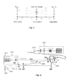
- the apparatus is similar to the apparatus described above in connection with figure 2 and comprises a 1342 nm Nd:YV04 laser 703 in a Z-shaped high finesse cavity 704 with an intra-cavity periodically poled KTP (PPKTP) crystal 705 for sum frequency generation.
- PPKTP periodically poled KTP
- the 1342 nm solid-state laser 703 comprises an 8 mm long a-cut Nd:YV04 crystal LC with a Nd-doping of 0.5 atm %.
- M1 is coated for high reflection at 1342 nm and high transmission at 808 nm.
- Mirrors M2 and M3 are coated for high reflection at 1342 nm and high transmission at 765 nm.
- the distance between M1 and M2 is 213 mm, the separation of M2 and M3 is 178 mm.
- the 1342 nm cavity 704 forms an approximately circular beam waist of 70 ⁇ m between mirror M2 and M3 inside the Brewster's cut PPKTP crystal 705.
- Lens arrangements 730 and 732 are arranged, together with a light scanner 715, along a common optical axis 742.
- Incoherent electromagnetic radiation 738 emanating from a spatially extended object 701, is conveyed by the scanner 715 to the lens arrangement 730 and focused inside the PPKTP crystal 705 in the cavity 704.
- the scanner 715 is configured such that it outputs scanned incoherent electromagnetic radiation 740 along the optical axis 742. That is, the scanned radiation 740 is time multiplexed such that, during a specific scan period, the scanner 715 scans the whole angular extent of the object 701 and sequentially outputs the scanned incoherent radiation 740 along the optical axis 742.
- a varaiation of this embodiment is to replace the extended object 701, the scanner 715 and the lens with a single mode fibre probe and a lens for collecting light. From LIDAR theory it is known that only light emitted from a small volume around the focus point formed by the fibre tip/lens combination will be efficiently coupled to the fibre. Such an arrangement will allow sampling of a small volume in "mid air” (e.g. inside a burning flame), without probing the intermidiate medium.
- Figure 8 is a diagram, similar to the diagram in figure 5 , illustrating energy conversion efficiency during imaging in an apparatus such as the one illustrated in figure 7 .
- the line 801 represents Ti:Sapphire and the line 803 represents a tapered diode.
- PPKTP crystals have been used in the examples described above, other crystals can be used, such as Brewster cut PP-LiNbO 3 or PP-LiOTiO 3 crystals.
- the laser sources described above may be operated in any desired mode, continuous wave as well as pulsed.
Landscapes
- Physics & Mathematics (AREA)
- Electromagnetism (AREA)
- Nonlinear Science (AREA)
- Engineering & Computer Science (AREA)
- Plasma & Fusion (AREA)
- Optics & Photonics (AREA)
- Optical Modulation, Optical Deflection, Nonlinear Optics, Optical Demodulation, Optical Logic Elements (AREA)
- Lasers (AREA)
Priority Applications (5)
| Application Number | Priority Date | Filing Date | Title |
|---|---|---|---|
| EP09158492A EP2146406A3 (fr) | 2008-07-18 | 2009-04-22 | Agencement optique et procédé |
| US13/054,420 US8971361B2 (en) | 2008-07-18 | 2009-07-09 | Optical arrangement and method |
| EP09780371.2A EP2319141B1 (fr) | 2008-07-18 | 2009-07-09 | Agencement optique et procédé |
| PCT/EP2009/058745 WO2010006985A2 (fr) | 2008-07-18 | 2009-07-09 | Système et procédé optiques |
| DK09780371.2T DK2319141T3 (en) | 2008-07-18 | 2009-07-09 | Optical device and method |
Applications Claiming Priority (2)
| Application Number | Priority Date | Filing Date | Title |
|---|---|---|---|
| EP08160696A EP2146405A1 (fr) | 2008-07-18 | 2008-07-18 | Agencement optique et procédé |
| EP09158492A EP2146406A3 (fr) | 2008-07-18 | 2009-04-22 | Agencement optique et procédé |
Publications (2)
| Publication Number | Publication Date |
|---|---|
| EP2146406A2 true EP2146406A2 (fr) | 2010-01-20 |
| EP2146406A3 EP2146406A3 (fr) | 2010-04-21 |
Family
ID=40210758
Family Applications (3)
| Application Number | Title | Priority Date | Filing Date |
|---|---|---|---|
| EP08160696A Withdrawn EP2146405A1 (fr) | 2008-07-18 | 2008-07-18 | Agencement optique et procédé |
| EP09158492A Withdrawn EP2146406A3 (fr) | 2008-07-18 | 2009-04-22 | Agencement optique et procédé |
| EP09780371.2A Active EP2319141B1 (fr) | 2008-07-18 | 2009-07-09 | Agencement optique et procédé |
Family Applications Before (1)
| Application Number | Title | Priority Date | Filing Date |
|---|---|---|---|
| EP08160696A Withdrawn EP2146405A1 (fr) | 2008-07-18 | 2008-07-18 | Agencement optique et procédé |
Family Applications After (1)
| Application Number | Title | Priority Date | Filing Date |
|---|---|---|---|
| EP09780371.2A Active EP2319141B1 (fr) | 2008-07-18 | 2009-07-09 | Agencement optique et procédé |
Country Status (4)
| Country | Link |
|---|---|
| US (1) | US8971361B2 (fr) |
| EP (3) | EP2146405A1 (fr) |
| DK (1) | DK2319141T3 (fr) |
| WO (1) | WO2010006985A2 (fr) |
Families Citing this family (12)
| Publication number | Priority date | Publication date | Assignee | Title |
|---|---|---|---|---|
| EP2567286A1 (fr) | 2010-05-04 | 2013-03-13 | Danmarks Tekniske Universitet | Conversion par élévation de rayonnement électromagnétique à l'intérieur d'une plage de longueurs d'onde |
| US20130156054A1 (en) * | 2010-08-06 | 2013-06-20 | University of North Texas System | Monolithic, fiber-to-fiber coupled nonlinear resonator for brewster cut periodically poled crystals |
| DK2727198T3 (en) * | 2011-06-28 | 2017-07-03 | Univ Danmarks Tekniske | SYSTEM AND METHOD OF TREATING ELECTROMAGNETIC RADIATION |
| US9413456B2 (en) * | 2012-07-20 | 2016-08-09 | The Boeing Company | Non-linear optical receiver |
| EP2951640A1 (fr) | 2013-01-31 | 2015-12-09 | Danmarks Tekniske Universitet | Télescope d'interpolation infrarouge |
| US9709789B2 (en) | 2013-01-31 | 2017-07-18 | Danmarks Tekniske Universitet | Infrared up-conversion microscope |
| DK3019912T3 (en) | 2013-07-09 | 2017-12-11 | Univ Danmarks Tekniske | MULTI-CHANNEL UP-CONVERSION OF INFRARED SPECTROMETER AND METHOD OF DETECTING A SPECTRAL DISTRIBUTION OF LIGHT |
| US10570801B2 (en) | 2016-06-24 | 2020-02-25 | Robert Bosch Gmbh | System and method of detecting an obstructed pressure line in a diesel exhaust fluid delivery system |
| US10732365B2 (en) * | 2016-11-29 | 2020-08-04 | Panasonic Intellectual Property Management Co., Ltd. | Core adjustment method |
| CN110571638B (zh) * | 2019-08-16 | 2021-11-02 | 华中科技大学 | 一种反射注入泵浦光的宽带双振荡参量振荡器 |
| CN114486788B (zh) * | 2021-09-29 | 2024-02-13 | 华东师范大学重庆研究院 | 一种大视场超灵敏的中红外频率上转换成像技术及装置 |
| CN114413794B (zh) * | 2022-01-29 | 2023-09-22 | 中国工程物理研究院激光聚变研究中心 | 大口径kdp晶体最佳相位匹配角测量系统及其测量方法 |
Citations (1)
| Publication number | Priority date | Publication date | Assignee | Title |
|---|---|---|---|---|
| EP0301803A2 (fr) | 1987-07-27 | 1989-02-01 | Amoco Corporation | Production intra-cavité de rayonnement optique cohérent par mélange optique |
Family Cites Families (12)
| Publication number | Priority date | Publication date | Assignee | Title |
|---|---|---|---|---|
| GB1248791A (en) * | 1968-01-31 | 1971-10-06 | Secr Defence | Infra-red image converters |
| US3629603A (en) * | 1970-02-20 | 1971-12-21 | Us Navy | Means and method for optical parametric up conversion of ir images |
| US4948212A (en) * | 1988-08-22 | 1990-08-14 | California Institute Of Technology | Optical processing in III-V and II-VI compound semiconductors |
| US5452312A (en) * | 1993-10-18 | 1995-09-19 | Matsushita Electric Industrial Co., Ltd. | Short-wavelength laser light source and optical information processing aparatus |
| JP3136071B2 (ja) * | 1995-04-14 | 2001-02-19 | シャープ株式会社 | 画像処理装置及び撮像装置 |
| US6982999B1 (en) * | 2003-01-21 | 2006-01-03 | Picarro,Inc. | Multipass second harmonic generation |
| AU2003262043A1 (en) * | 2002-09-10 | 2004-04-30 | The Furukawa Electric Co., Ltd. | Wavelength conversion module |
| ATE400911T1 (de) * | 2004-06-16 | 2008-07-15 | Univ Danmarks Tekniske | Segmentiertes diodenlasersystem |
| US7322704B2 (en) * | 2004-07-30 | 2008-01-29 | Novalux, Inc. | Frequency stabilized vertical extended cavity surface emitting lasers |
| US7705990B2 (en) * | 2006-08-04 | 2010-04-27 | Agilent Technologies, Inc. | Optical sources for SPR applications |
| US7330300B1 (en) * | 2006-08-21 | 2008-02-12 | Hc Photonics Corp. | Optical frequency mixer and method for the same |
| US7813390B2 (en) * | 2007-08-29 | 2010-10-12 | Pavilion Integration Corporation | Injection-seeded monolithic laser |
-
2008
- 2008-07-18 EP EP08160696A patent/EP2146405A1/fr not_active Withdrawn
-
2009
- 2009-04-22 EP EP09158492A patent/EP2146406A3/fr not_active Withdrawn
- 2009-07-09 DK DK09780371.2T patent/DK2319141T3/en active
- 2009-07-09 WO PCT/EP2009/058745 patent/WO2010006985A2/fr not_active Ceased
- 2009-07-09 US US13/054,420 patent/US8971361B2/en active Active
- 2009-07-09 EP EP09780371.2A patent/EP2319141B1/fr active Active
Patent Citations (1)
| Publication number | Priority date | Publication date | Assignee | Title |
|---|---|---|---|---|
| EP0301803A2 (fr) | 1987-07-27 | 1989-02-01 | Amoco Corporation | Production intra-cavité de rayonnement optique cohérent par mélange optique |
Non-Patent Citations (2)
| Title |
|---|
| BEAMS, G.D. BOYD; D.A. KLEINMAN: "Parametric Interaction of Focussed Gaussian Light", J. OF APPLIED PHYSICS, vol. 39, no. 8, 1968, pages 3597 - 3641 |
| JOSEPH W. GOODMAN: "Introduction to Fourier Optics", 2005 |
Also Published As
| Publication number | Publication date |
|---|---|
| EP2146406A3 (fr) | 2010-04-21 |
| WO2010006985A3 (fr) | 2010-06-10 |
| EP2319141B1 (fr) | 2018-08-22 |
| US20110228807A1 (en) | 2011-09-22 |
| US8971361B2 (en) | 2015-03-03 |
| EP2319141A2 (fr) | 2011-05-11 |
| EP2146405A1 (fr) | 2010-01-20 |
| DK2319141T3 (en) | 2018-11-26 |
| WO2010006985A2 (fr) | 2010-01-21 |
Similar Documents
| Publication | Publication Date | Title |
|---|---|---|
| EP2146406A2 (fr) | Agencement optique et procédé | |
| US7672342B2 (en) | Method and radiation source for generating pulsed coherent radiation | |
| US6320886B1 (en) | Laser device | |
| USRE35215E (en) | Frequency converted laser diode and lens system therefor | |
| US9588398B2 (en) | Gigahertz to terahertz frequency signal generation using OPO and DFG | |
| Berrou et al. | High-resolution photoacoustic and direct absorption spectroscopy of main greenhouse gases by use of a pulsed entangled cavity doubly resonant OPO | |
| US11226534B2 (en) | Methods and apparatus for generating mid-infrared frequency combs | |
| JP2002099007A (ja) | レーザ光発生装置およびそれを用いた光学装置 | |
| Bisson et al. | Broadly tunable, mode-hop-tuned cw optical parametric oscillator based on periodically poled lithium niobate | |
| US20050243876A1 (en) | Narrow bandwidth high repetition rate optical parametric oscillator | |
| US20080055702A1 (en) | Method and Device for Multiplying Optical Frequencies by a Factor 1.5 | |
| CN111226169A (zh) | 具有宽带输出的可调谐光源 | |
| DK2727198T3 (en) | SYSTEM AND METHOD OF TREATING ELECTROMAGNETIC RADIATION | |
| Siltanen et al. | Pump-tunable continuous-wave singly resonant optical parametric oscillator from 2.5 to 4.4 µm | |
| EP3685224A1 (fr) | Source de lumière avec sortie d'onde continue à mode multi-longitudinal basée sur une technologie opo résonante multimode | |
| JP2010050389A (ja) | レーザ光発生装置 | |
| Nieuwenhuis et al. | One-Watt level mid-IR output, singly resonant, continuous-wave optical parametric oscillator pumped by a monolithic diode laser | |
| Bae et al. | Mid-infrared Continuous-wave Optical Parametric Oscillator with a Fan-out Grating MgO: PPLN Operating Up to 5.3 µm | |
| JP2008058918A (ja) | テラヘルツ電磁波発生方法及び分光・イメージング測定装置 | |
| Zhang et al. | A nanosecond optical parameter oscillator at 2.6 μm with near diffraction limit beam | |
| Bisson et al. | A broadly tunable high-resolution IR cavity ring-down spectrometer based on difference frequency generation in orientation-patterned GaAs | |
| Nieuwenhuis et al. | A CrTmHo: YAG laser pumped ZnGeP2 optical parametric oscillator for mid-infrared spectroscopy | |
| Grässer et al. | Continuous-wave mode-locked AgGaSe2 optical parametric oscillator tunable from 4 to 8 μm | |
| Jensen et al. | Generation of more than 300 mW diffraction-limited light at 405 nm by second-harmonic generation of a tapered diode laser with external cavity feedback | |
| Zadorozhnii et al. | Wide-band and wide-angle nonlinear conversion of signals and images in uniaxial and biaxial crystals |
Legal Events
| Date | Code | Title | Description |
|---|---|---|---|
| PUAI | Public reference made under article 153(3) epc to a published international application that has entered the european phase |
Free format text: ORIGINAL CODE: 0009012 |
|
| AK | Designated contracting states |
Kind code of ref document: A2 Designated state(s): AT BE BG CH CY CZ DE DK EE ES FI FR GB GR HR HU IE IS IT LI LT LU LV MC MK MT NL NO PL PT RO SE SI SK TR |
|
| PUAL | Search report despatched |
Free format text: ORIGINAL CODE: 0009013 |
|
| AK | Designated contracting states |
Kind code of ref document: A3 Designated state(s): AT BE BG CH CY CZ DE DK EE ES FI FR GB GR HR HU IE IS IT LI LT LU LV MC MK MT NL NO PL PT RO SE SI SK TR |
|
| STAA | Information on the status of an ep patent application or granted ep patent |
Free format text: STATUS: THE APPLICATION HAS BEEN WITHDRAWN |
|
| 18W | Application withdrawn |
Effective date: 20100909 |