EP2146563B1 - Solution de circulation d'air/refroidissement pour châssis - Google Patents
Solution de circulation d'air/refroidissement pour châssis Download PDFInfo
- Publication number
- EP2146563B1 EP2146563B1 EP08253245.8A EP08253245A EP2146563B1 EP 2146563 B1 EP2146563 B1 EP 2146563B1 EP 08253245 A EP08253245 A EP 08253245A EP 2146563 B1 EP2146563 B1 EP 2146563B1
- Authority
- EP
- European Patent Office
- Prior art keywords
- modules
- openings
- plenum
- module
- air
- Prior art date
- Legal status (The legal status is an assumption and is not a legal conclusion. Google has not performed a legal analysis and makes no representation as to the accuracy of the status listed.)
- Ceased
Links
Images



Classifications
-
- H—ELECTRICITY
- H05—ELECTRIC TECHNIQUES NOT OTHERWISE PROVIDED FOR
- H05K—PRINTED CIRCUITS; CASINGS OR CONSTRUCTIONAL DETAILS OF ELECTRIC APPARATUS; MANUFACTURE OF ASSEMBLAGES OF ELECTRICAL COMPONENTS
- H05K7/00—Constructional details common to different types of electric apparatus
- H05K7/20—Modifications to facilitate cooling, ventilating, or heating
- H05K7/20536—Modifications to facilitate cooling, ventilating, or heating for racks or cabinets of standardised dimensions, e.g. electronic racks for aircraft or telecommunication equipment
- H05K7/20554—Forced ventilation of a gaseous coolant
- H05K7/20563—Forced ventilation of a gaseous coolant within sub-racks for removing heat from electronic boards
Definitions
- the present invention relates to the field of cooling systems, and in particular to cooling of a modular chassis with orthogonal modules.
- the orthogonal configuration also creates a cooling challenge, especially in applications where front-to-back cooling is required.
- Vertical cards can be cooled using conventional cooling mechanisms with front air intake and rear air exhaust, but cooling the horizontal cards while maintaining overall front-to-back air flow is challenging.
- the horizontal card cage can be cooled using side-to-side air flow.
- many rack mount environments require front-to-back air cooling.
- One solution has been to divert air taken from a front intake to the back and run it up in a column next to the horizontal cards.
- Such a mechanism typically uses a set of fans or blowers to create the air pressure across the horizontal cards.
- the amount of air flow that is provided in such a system is typically limited due the number of turns in the air path.
- the placement of one or two fan blades along the sides of the horizontal cards can severely limit the PCB area and panel surface that is available.
- US 2005/207134 discloses a cell board interconnection architecture comprises an interconnection structure for interconnecting a plurality of cell boards, the interconnection structure configured to allow air to pass therethrough in a direction in which the cell boards couple therewith.
- US 2006/0126292 discusses an air cooling architecture for orthogonal board architectures.
- An apparatus comprises a chassis having an opening in a front wall of the chassis.
- a first plurality of modules is mounted vertically in the chassis.
- a second plurality of modules is mounted horizontally in the chassis orthogonally to the first plurality of modules.
- a midplane is positioned between and electrically connecting the first plurality of modules and the second plurality of modules, the midplane including an opening. Means are provided for moving air through the opening in the midplane
- a plenum is defined between a pair of the first plurality of modules, the plenum comprising a pair of walls positioned on opposite sides of the opening in the front wall and the opening formed through the midplane and providing fluid communication between the opening through the front wall and the opening through the midplane.
- a method of cooling such an apparatus comprises: moving air from a front of the apparatus through the plenum, through the opening in the midplane and across a surface of a module of the second plurality of modules; and exhausting the air at a rear of the apparatus.
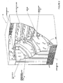
- Figure 1 is a cutaway perspective view illustrating a chassis and plenums according to one embodiment
- Figure 2 is a cutaway perspective view illustrating a chassis and plenums according to a second embodiment
- Figure 3 is a cutaway perspective view illustrating a chassis and plenums according to a third embodiment.
- Figure 4 is a top perspective view of the embodiment of Figure 1 .
- Fig. 1 is a cutaway perspective view of a chassis 100.
- a plurality of modules 110 typically circuit boards, are mounted in a vertical orientation in the front of the chassis 100.
- a plurality of modules 150 also typically circuit boards, are mounted orthogonally to the plurality of modules 110 and a horizontal orientation in the rear of the chassis 100.
- a midplane 140 is positioned between the modules 110 and the modules 150 to electrically connect the modules 110 and 150.
- a plurality of openings or holes is formed through the midplane 140 to allow air flow to the rear modules 150.
- the plurality of openings 130 is distributed evenly across the midplane 140, but this arrangement and number of holes is illustrative only and any desired arrangement and number of openings 130 can be formed in the midplane 140 as needed because of heating characteristics of the modules 150. For example, if some of the modules 150 generate more heat than others of the modules 150, then the midplane 140 may have more openings 130 to provide more air flow to the hotter modules 150. Similarly, if some portions of one of the modules 150 require more cooling than others, more or bigger holes could be placed at or near that portion of the modules 150, while fewer or smaller holes 130 could be placed near the cooler portion of the modules 150. At least one opening 130 must correspond to each of the rear modules 150. The openings 130 are preferably sized to provide sufficient air flow across the rear modules 150 to provide appropriate cooling for the modules 150. More than one opening 130 may be formed for each horizontal module 150 as desired and as electrical circuit positioning constraints on the midplane 150 allow.
- Heated air from the first and second plurality of modules is exhausted rearwards from the horizontal modules 150 and the vertical modules 110 through exhaust outlets 160 on the rear of the chassis 100.
- air flow across the vertically oriented modules 110 is driven by a lower fan tray 180 containing fans that take air from a lower air intake 170 and blow air vertically across the modules 110.
- An upper fan tray 190 can provide additional air flow to take heated air from the vertical modules 110 and exhaust the air to the rear of the chassis 100 through a plenum 240 through exhaust outlets 160.
- Fig. 1 provides a plurality of plenums 120 that allow air flow from a plurality of front inlets 175 of the chassis 100 through one or more of the openings 130 in the midplane 140.
- Two walls, closed at the top and bottom form a rectangular plenum 120 open to the front of the chassis 100 through upper air intakes 175.
- the pitch of the modules 110 must be sufficient to allow placement of the plenums 120 between a pair of modules 110.
- the plenums 120 provide at least a one quarter inch air gap, but preferably, the plenums 120 provide at least a one half inch air gap.
- the cooling of the front vertical modules 110 is independent of the cooling of the rear horizontal modules 150.
- negative pressure is used to pull air from the upper front intakes 175 through the plenum 120 and openings 130. The air is then drawn across the surface of the rear modules 150 and exhausted through rear outlets 160.
- FIG. 4 is a top perspective view of the chassis 100 illustrating an example fan configuration. As shown in Fig. 4 , two fans or blowers 410 on each rear module 150 pull air from the openings 130 in the midplane 140. In other embodiments, a single fan or blower 410 could be used, typically in a central rear position. Alternatively, one or more fans could be mounted distal to a line from one of the openings 130 to the rear of the chassis 100 at the sides of the modules 150. At least one fan 410 would need to be mounted with each rear module 150 in embodiments such as illustrated in Figs. 1 and 4 .
- Figs. 2 and 3 illustrate alternative embodiments that divide air flow between the plenums 120 and the vertical front modules 110, using fans in fan tray 180 to push air through the plenums 120 and through the openings 130 to the rear modules 150.
- the fans 410 of Fig. 4 may not be necessary to achieve sufficient air flow, but in some embodiments can be used to improve air flow and cooling across the rear modules 150.
- the plenums 210 and 310 are not open to the front, like the plenums 120, so the upper front air intakes 175 of Fig. 1 are not required. Instead, the plenums 210 and 310 are open to the bottom to allow air to be pushed through the plenums 210 and 310 by the fans of fan tray 180. In embodiments as illustrated in Fig. 2 , the plenums 210 are closed on top with vertical walls forming a rectangular plenum 210 where the air makes a turn to exit the plenums 210 through openings 130. As with the embodiments illustrated by Fig. 1 , the pitch of the modules must be sufficient to allow insertion of the separate plenum units 210 between a pair of modules 110.
- Embodiments illustrated by Fig. 3 are similar to those illustrated by Fig. 2 , but instead of using separate plenum units 210, they take advantage of the common practice of mounting modules 110 in a carrier or tray 320 for insertion into the chassis 100.
- the carriers 320 and modules 110 together form plenum 310 that can be aligned with openings 130 to provide cooling air flow through the openings 130 to cool the rear modules 150.
- air flow is provided by the fans of the fan tray 180 and the air flow is divided between cooling the modules 110 and the plenum 310.
- the air gap forming the plenum 310 can be as small as one quarter inch, but preferably the air gap is at least one half inch.
- the size of the plenums 310 is engineered based on the cooling needs of the rear modules 150. Use of embodiments similar to that illustrated in Fig. 3 avoids the need for separate plenum units 210 and can allow for closer spacing of the modules 110.
- air passed over the vertical front modules 110 is exhausted through a plenum 240 formed or defined above the horizontal modules 150 and exhausted through upper air exhausts 160.
Landscapes
- Engineering & Computer Science (AREA)
- Aviation & Aerospace Engineering (AREA)
- Physics & Mathematics (AREA)
- Thermal Sciences (AREA)
- Microelectronics & Electronic Packaging (AREA)
- Cooling Or The Like Of Electrical Apparatus (AREA)
Claims (17)
- Dispositif, comprenant:un châssis (100);une pluralité d'ouvertures (175) dans une paroi avant du châssis;une première pluralité de modules (110) montés verticalement dans le châssis;une deuxième pluralité de modules (150) montés horizontalement dans le châssis de façon orthogonale à la première pluralité de modules;un plan intermédiaire (140) positionné entre et connectant électriquement la première pluralité de modules et la deuxième pluralité de modules, le plan intermédiaire comportant une pluralité d'ouvertures (130);des moyens (410) pour déplacer de l'air à travers la pluralité d'ouvertures dans le plan intermédiaire; etune pluralité de plénums (120), chaque plénum étant défini entre une paire de la première pluralité de modules, et chaque plénum comprenant une paire de parois positionnées sur des côtés opposés de l'une de la pluralité d'ouvertures dans la paroi avant et de l'une de la pluralité d'ouvertures formées à travers le plan intermédiaire et établissant une communication fluidique entre une de la pluralité d'ouvertures à travers la paroi avant et une de la pluralité d'ouvertures à travers le plan intermédiaire.
- Dispositif selon la revendication 1, dans lequel les moyens pour déplacer de l'air comprennent des moyens pour aspirer de l'air à travers la pluralité d'ouvertures et en travers d'une surface d'un module de la deuxième pluralité de modules.
- Dispositif selon la revendication 1 ou la revendication 2, dans lequel le plénum est configuré de manière à diviser un écoulement d'air entre la première pluralité de modules et la deuxième pluralité de modules.
- Dispositif selon l'une quelconque des revendications 1 à 3, comprenant des moyens pour refroidir la première pluralité de modules, dans lequel le plénum est indépendant des moyens pour refroidir la première pluralité de modules.
- Dispositif selon l'une quelconque des revendications 1 à 4, dans lequel les moyens pour déplacer de l'air à travers la pluralité d'ouvertures comprennent un ventilateur configuré pour déplacer de l'air à travers la pluralité d'ouvertures à partir du plénum et en travers d'une surface d'un module de la deuxième pluralité de modules.
- Dispositif selon la revendication 5, dans lequel:le ventilateur est positionné sur la surface du module de la deuxième pluralité de modules, etle ventilateur est configuré de manière à aspirer de l'air à travers la pluralité d'ouvertures en travers de la surface du module de la deuxième pluralité de modules.
- Dispositif selon la revendication 5 ou la revendication 6, dans lequel le ventilateur est positionné à un centre d'un bord arrière du module.
- Dispositif selon la revendication 5 ou la revendication 6, dans lequel le ventilateur est positionné à distance d'une ligne qui s'étend à partir de la pluralité d'ouvertures jusqu'à un bord arrière du module.
- Dispositif selon l'une quelconque des revendications 5 à 8, dans lequel:une de la pluralité d'ouvertures dans la paroi avant est alignée avec une de la pluralité d'ouvertures formées dans le plan intermédiaire; etla paire de parois est positionnée en parallèle.
- Dispositif selon l'une quelconque des revendications 5 à 9, dans lequel:le ventilateur est positionné en-dessous de la première pluralité de modules; etle ventilateur est configuré de manière à pousser de l'air à travers le plénum jusqu'à la pluralité d'ouvertures à travers le plan intermédiaire.
- Dispositif selon l'une quelconque des revendications 5 à 12, comprenant un support, dans lequel:un module de la première pluralité de modules est monté dans le support, etune paroi du support est espacée d'une surface du module, le plénum étant défini entre la paroi du support et le module.
- Procédé de refroidissement d'un dispositif selon l'une quelconque des revendications 1 à 11, comprenant les étapes suivantes:déplacer de l'air à partir de l'avant du dispositif à travers le plénum, à travers la pluralité d'ouvertures dans le plan intermédiaire, et en travers d'une surface d'un module de la deuxième pluralité de modules; etlaisser s'échapper l'air à l'arrière du dispositif.
- Procédé selon la revendication 12, dans lequel le déplacement d'air à partir de l'avant du dispositif à travers le plénum, à travers la pluralité d'ouvertures et en travers d'une surface d'un module de la deuxième pluralité de modules, comprend les étapes suivantes:aspirer l'air à l'aide d'un ventilateur positionné sur un module de la deuxième pluralité de modules à travers la pluralité d'ouvertures dans le plan intermédiaire à partir du plénum en travers de la surface du module de la deuxième pluralité de modules; etpousser de l'air à l'aide du ventilateur hors de l'arrière du dispositif.
- Procédé selon la revendication 13 ou la revendication 14, comprenant en outre le refroidissement de la première pluralité de modules indépendamment de la deuxième pluralité de modules.
- Procédé selon l'une quelconque des revendications 12 à 14, dans lequel le plénum est ouvert vers l'avant du dispositif.
- Procédé selon la revendication 12, dans lequel le déplacement d'air à partir de l'avant du dispositif à travers le plénum, à travers la pluralité d'ouvertures et en travers d'une surface d'un module de la deuxième pluralité de modules comprend la poussée d'air à l'aide d'un ventilateur, qui est positionné en-dessous de la première pluralité de modules et avec le plénum ouvert vers le ventilateur, dans le plénum et à travers la pluralité d'ouvertures dans le plan intermédiaire en travers de la surface du module de la deuxième pluralité de modules.
- Procédé selon l'une quelconque des revendications 12 à 16, comprenant les étapes suivantes:positionner un de la paire de modules dans un support approprié pour être monté dans le dispositif; etformer le plénum entre une paroi du support et une surface du module, le plénum permettant un déplacement d'air depuis le dessous du support et du module jusque l'une de la pluralité d'ouvertures dans le plan intermédiaire.
Applications Claiming Priority (1)
| Application Number | Priority Date | Filing Date | Title |
|---|---|---|---|
| US12/175,291 US7885066B2 (en) | 2008-07-17 | 2008-07-17 | Airflow/cooling solution for chassis with orthogonal boards |
Publications (3)
| Publication Number | Publication Date |
|---|---|
| EP2146563A2 EP2146563A2 (fr) | 2010-01-20 |
| EP2146563A3 EP2146563A3 (fr) | 2011-05-25 |
| EP2146563B1 true EP2146563B1 (fr) | 2014-03-12 |
Family
ID=40090225
Family Applications (1)
| Application Number | Title | Priority Date | Filing Date |
|---|---|---|---|
| EP08253245.8A Ceased EP2146563B1 (fr) | 2008-07-17 | 2008-10-06 | Solution de circulation d'air/refroidissement pour châssis |
Country Status (3)
| Country | Link |
|---|---|
| US (1) | US7885066B2 (fr) |
| EP (1) | EP2146563B1 (fr) |
| CN (1) | CN101631447B (fr) |
Families Citing this family (38)
| Publication number | Priority date | Publication date | Assignee | Title |
|---|---|---|---|---|
| US7826222B2 (en) * | 2008-07-03 | 2010-11-02 | Juniper Networks, Inc. | Front-to-back cooling system for modular systems with orthogonal midplane configuration |
| US7839637B2 (en) * | 2008-09-24 | 2010-11-23 | Cisco Technology, Inc. | Air-cooling of electronics cards |
| US7804684B1 (en) | 2008-12-22 | 2010-09-28 | Juniper Networks, Inc. | Cooling system for a data processing unit |
| US8535787B1 (en) | 2009-06-29 | 2013-09-17 | Juniper Networks, Inc. | Heat sinks having a thermal interface for cooling electronic devices |
| US8534930B1 (en) | 2009-09-24 | 2013-09-17 | Juniper Networks, Inc. | Circuit boards defining openings for cooling electronic devices |
| US8801374B1 (en) | 2009-10-07 | 2014-08-12 | Juniper Networks, Inc. | Fan trays having stator blades for improving air flow performance |
| US8223498B2 (en) * | 2009-11-11 | 2012-07-17 | Juniper Networks, Inc. | Thermal interface members for removable electronic devices |
| US8279601B2 (en) * | 2010-01-28 | 2012-10-02 | Juniper Networks, Inc. | Air flow ducts for cooling electronic devices within a data processing unit |
| JP5315323B2 (ja) * | 2010-11-17 | 2013-10-16 | アラクサラネットワークス株式会社 | 電子装置 |
| US8854814B2 (en) * | 2011-06-27 | 2014-10-07 | Futurewei Technologies, Inc. | Hybrid cooling design for modular systems |
| US9039432B2 (en) | 2011-07-08 | 2015-05-26 | Cisco Technology, Inc. | System and method for high connectivity platform |
| CN103907411B (zh) * | 2011-10-31 | 2016-05-18 | 泰拉丁公司 | 用于控制物体的温度的设备 |
| CN102510707B (zh) * | 2011-11-01 | 2014-08-13 | 华为技术有限公司 | 散热系统及具有该散热系统的电子设备 |
| US20130267160A1 (en) * | 2012-04-09 | 2013-10-10 | Chun Long Technology Co., Ltd. | Air distribution structure of industrial cabinet |
| US9560793B2 (en) * | 2012-04-27 | 2017-01-31 | Hewlett Packard Enterprise Development Lp | Blade enclosure |
| US9148975B2 (en) * | 2012-06-22 | 2015-09-29 | Advanced Micro Devices, Inc. | Electronic interconnect method and apparatus |
| US9116660B1 (en) * | 2012-08-31 | 2015-08-25 | Extreme Networks, Inc. | Midplane for orthogonal direct connection |
| US9253927B1 (en) | 2012-09-28 | 2016-02-02 | Juniper Networks, Inc. | Removable fan tray |
| GB2511278A (en) * | 2012-11-02 | 2014-09-03 | Greg James Compton | Computing equipment enclosure |
| US8922992B2 (en) * | 2012-11-12 | 2014-12-30 | Dell Products L.P. | System and design of cost effective chassis design for networking products |
| US9274548B2 (en) * | 2013-03-01 | 2016-03-01 | Seagate Technology Llc | Electronic apparatus comprising backplane and methods of assembling and disassembling |
| US9141156B2 (en) | 2013-08-02 | 2015-09-22 | Amazon Technologies, Inc. | Compute node cooling with air fed through backplane |
| CN203691803U (zh) * | 2013-12-27 | 2014-07-02 | 中兴通讯股份有限公司 | 一种插箱及终端 |
| US9603280B2 (en) | 2014-05-30 | 2017-03-21 | EMC IP Holding Company LLC | Flash module |
| US9398720B1 (en) * | 2014-05-30 | 2016-07-19 | Emc Corporation | Chassis with airflow and thermal management |
| US9362641B2 (en) | 2014-07-01 | 2016-06-07 | Telefonaktiebolaget L M Ericsson (Publ) | Orthogonal backplane design with reduced chassis depth |
| CN105592667A (zh) * | 2014-10-24 | 2016-05-18 | 华为技术有限公司 | 网络设备 |
| US9811969B2 (en) | 2015-03-30 | 2017-11-07 | Bally Gaming, Inc. | Removable fan assembly providing multi-directional air flow for a wagering game machine |
| US10390462B2 (en) * | 2017-02-16 | 2019-08-20 | Dell Products, Lp | Server chassis with independent orthogonal airflow layout |
| US10841246B2 (en) * | 2017-08-30 | 2020-11-17 | Arista Networks, Inc. | Distributed core switching with orthogonal fabric card and line cards |
| US10512187B2 (en) * | 2017-09-05 | 2019-12-17 | Quanta Computer Inc. | Alignment device for orthogonal engagement of line cards and fabric cards in a server |
| CN109008460B (zh) * | 2018-09-12 | 2020-07-10 | 李田 | 一种便于携带的书本包装展示架 |
| US11191185B2 (en) | 2018-09-14 | 2021-11-30 | Cisco Technology, Inc. | Liquid cooling distribution in a modular electronic system |
| US10582639B1 (en) * | 2018-09-14 | 2020-03-03 | Cisco Technology, Inc. | Liquid cooling distribution in a modular electronic system |
| US10986423B2 (en) | 2019-04-11 | 2021-04-20 | Arista Networks, Inc. | Network device with compact chassis |
| US11266007B2 (en) | 2019-09-18 | 2022-03-01 | Arista Networks, Inc. | Linecard system using riser printed circuit boards (PCBS) |
| CN114126311B (zh) * | 2020-08-31 | 2025-08-22 | 中兴通讯股份有限公司 | 线缆连接结构、单板组件、单板组件连接结构 |
| US12382604B2 (en) * | 2023-05-01 | 2025-08-05 | Caterpillar Inc. | Cooling system for electrical components |
Citations (1)
| Publication number | Priority date | Publication date | Assignee | Title |
|---|---|---|---|---|
| US20060126292A1 (en) * | 2004-12-14 | 2006-06-15 | Pfahnl Andreas C | Air cooling architecture for orthogonal board architectures |
Family Cites Families (8)
| Publication number | Priority date | Publication date | Assignee | Title |
|---|---|---|---|---|
| US4399485A (en) * | 1980-03-24 | 1983-08-16 | Ampex Corporation | Air baffle assembly for electronic circuit mounting frame |
| US6512672B1 (en) * | 2000-12-29 | 2003-01-28 | Cisco Technology, Inc. | Modular air flow distribution system |
| US20050207134A1 (en) * | 2004-03-16 | 2005-09-22 | Belady Christian L | Cell board interconnection architecture |
| US7164581B2 (en) * | 2004-06-21 | 2007-01-16 | Computer Network Technology Corp. | Modular chassis divided along a midplane and cooling system therefor |
| WO2006059923A1 (fr) * | 2004-11-30 | 2006-06-08 | Telefonaktiebolaget Lm Ericsson (Publ) | Ensemble carte a circuit imprime avec dissipation de la chaleur amelioree |
| US7652891B2 (en) * | 2004-12-06 | 2010-01-26 | Radisys Corporation | Airflow control system |
| US7593229B2 (en) * | 2006-03-31 | 2009-09-22 | Hong Kong Applied Science & Technology Research Institute Co. Ltd | Heat exchange enhancement |
| WO2008003038A2 (fr) * | 2006-06-29 | 2008-01-03 | Se2 Labs | Systèmes et procédés de refroidissement amélioré de composants électriques |
-
2008
- 2008-07-17 US US12/175,291 patent/US7885066B2/en not_active Expired - Fee Related
- 2008-09-27 CN CN2008101669756A patent/CN101631447B/zh not_active Expired - Fee Related
- 2008-10-06 EP EP08253245.8A patent/EP2146563B1/fr not_active Ceased
Patent Citations (1)
| Publication number | Priority date | Publication date | Assignee | Title |
|---|---|---|---|---|
| US20060126292A1 (en) * | 2004-12-14 | 2006-06-15 | Pfahnl Andreas C | Air cooling architecture for orthogonal board architectures |
Also Published As
| Publication number | Publication date |
|---|---|
| US20100014248A1 (en) | 2010-01-21 |
| US7885066B2 (en) | 2011-02-08 |
| CN101631447A (zh) | 2010-01-20 |
| CN101631447B (zh) | 2012-06-13 |
| EP2146563A2 (fr) | 2010-01-20 |
| EP2146563A3 (fr) | 2011-05-25 |
Similar Documents
| Publication | Publication Date | Title |
|---|---|---|
| US7885066B2 (en) | Airflow/cooling solution for chassis with orthogonal boards | |
| EP2720524B1 (fr) | Système de refroidissement d'avant en arrière pour systèmes modulaires à configuration orthogonale dans le plan moyen | |
| US9510483B1 (en) | Cooling a chassis by moving air through a midplane between two sets of channels oriented laterally relative to one another | |
| US8634190B2 (en) | Single fan tray in a midplane architecture | |
| US7280356B2 (en) | Air cooling architecture for orthogonal board architectures | |
| CN1902948B (zh) | 模块化平台系统、方法及装置 | |
| US5497288A (en) | Apparatus for tilted serial cooling in an electronic system | |
| CN104871656A (zh) | 轴向对齐的电子机架 | |
| CA2661794A1 (fr) | Baie electronique associant convection naturelle et circulation d'air force pour son refroidissement | |
| US4682268A (en) | Mounting structure for electronic circuit modules | |
| US20120327597A1 (en) | Hybrid Cooling Design for Modular Systems | |
| WO2014101201A1 (fr) | Système de dissipation thermique pour dispositif de communication | |
| US9116660B1 (en) | Midplane for orthogonal direct connection | |
| US20080218949A1 (en) | Enclosure for containing one or more electronic devices and cooling module | |
| US20190357390A1 (en) | Fan apparatuses for chassis airflow | |
| WO2017198174A1 (fr) | Système d'armoire | |
| US20190357380A1 (en) | Apparatuses to vent air therethrough | |
| US11317533B2 (en) | Heat sink arrangements for data storage systems | |
| JP2004146631A (ja) | 電子機器 | |
| JP2012129331A (ja) | 電子装置 | |
| JP2006521620A (ja) | 冷却を向上させるよう構成されたコンピュータシステムおよび方法 |
Legal Events
| Date | Code | Title | Description |
|---|---|---|---|
| PUAI | Public reference made under article 153(3) epc to a published international application that has entered the european phase |
Free format text: ORIGINAL CODE: 0009012 |
|
| AK | Designated contracting states |
Kind code of ref document: A2 Designated state(s): AT BE BG CH CY CZ DE DK EE ES FI FR GB GR HR HU IE IS IT LI LT LU LV MC MT NL NO PL PT RO SE SI SK TR |
|
| AX | Request for extension of the european patent |
Extension state: AL BA MK RS |
|
| PUAL | Search report despatched |
Free format text: ORIGINAL CODE: 0009013 |
|
| AK | Designated contracting states |
Kind code of ref document: A3 Designated state(s): AT BE BG CH CY CZ DE DK EE ES FI FR GB GR HR HU IE IS IT LI LT LU LV MC MT NL NO PL PT RO SE SI SK TR |
|
| AX | Request for extension of the european patent |
Extension state: AL BA MK RS |
|
| 17P | Request for examination filed |
Effective date: 20111123 |
|
| AKX | Designation fees paid |
Designated state(s): DE FR GB NL |
|
| 17Q | First examination report despatched |
Effective date: 20120719 |
|
| GRAP | Despatch of communication of intention to grant a patent |
Free format text: ORIGINAL CODE: EPIDOSNIGR1 |
|
| INTG | Intention to grant announced |
Effective date: 20131016 |
|
| GRAS | Grant fee paid |
Free format text: ORIGINAL CODE: EPIDOSNIGR3 |
|
| GRAA | (expected) grant |
Free format text: ORIGINAL CODE: 0009210 |
|
| AK | Designated contracting states |
Kind code of ref document: B1 Designated state(s): DE FR GB NL |
|
| REG | Reference to a national code |
Ref country code: GB Ref legal event code: FG4D |
|
| REG | Reference to a national code |
Ref country code: DE Ref legal event code: R096 Ref document number: 602008030771 Country of ref document: DE Effective date: 20140424 |
|
| REG | Reference to a national code |
Ref country code: NL Ref legal event code: T3 |
|
| REG | Reference to a national code |
Ref country code: DE Ref legal event code: R097 Ref document number: 602008030771 Country of ref document: DE |
|
| PLBE | No opposition filed within time limit |
Free format text: ORIGINAL CODE: 0009261 |
|
| STAA | Information on the status of an ep patent application or granted ep patent |
Free format text: STATUS: NO OPPOSITION FILED WITHIN TIME LIMIT |
|
| 26N | No opposition filed |
Effective date: 20141215 |
|
| REG | Reference to a national code |
Ref country code: DE Ref legal event code: R097 Ref document number: 602008030771 Country of ref document: DE Effective date: 20141215 |
|
| REG | Reference to a national code |
Ref country code: FR Ref legal event code: PLFP Year of fee payment: 8 |
|
| REG | Reference to a national code |
Ref country code: FR Ref legal event code: PLFP Year of fee payment: 9 |
|
| REG | Reference to a national code |
Ref country code: FR Ref legal event code: PLFP Year of fee payment: 10 |
|
| PGFP | Annual fee paid to national office [announced via postgrant information from national office to epo] |
Ref country code: NL Payment date: 20171026 Year of fee payment: 10 |
|
| REG | Reference to a national code |
Ref country code: FR Ref legal event code: PLFP Year of fee payment: 11 |
|
| REG | Reference to a national code |
Ref country code: NL Ref legal event code: MM Effective date: 20181101 |
|
| PG25 | Lapsed in a contracting state [announced via postgrant information from national office to epo] |
Ref country code: NL Free format text: LAPSE BECAUSE OF NON-PAYMENT OF DUE FEES Effective date: 20181101 |
|
| REG | Reference to a national code |
Ref country code: DE Ref legal event code: R082 Ref document number: 602008030771 Country of ref document: DE Representative=s name: D YOUNG & CO LLP, DE |
|
| PGFP | Annual fee paid to national office [announced via postgrant information from national office to epo] |
Ref country code: GB Payment date: 20200921 Year of fee payment: 13 Ref country code: FR Payment date: 20200917 Year of fee payment: 13 |
|
| PGFP | Annual fee paid to national office [announced via postgrant information from national office to epo] |
Ref country code: DE Payment date: 20200917 Year of fee payment: 13 |
|
| REG | Reference to a national code |
Ref country code: DE Ref legal event code: R119 Ref document number: 602008030771 Country of ref document: DE |
|
| GBPC | Gb: european patent ceased through non-payment of renewal fee |
Effective date: 20211006 |
|
| PG25 | Lapsed in a contracting state [announced via postgrant information from national office to epo] |
Ref country code: GB Free format text: LAPSE BECAUSE OF NON-PAYMENT OF DUE FEES Effective date: 20211006 Ref country code: DE Free format text: LAPSE BECAUSE OF NON-PAYMENT OF DUE FEES Effective date: 20220503 |
|
| PG25 | Lapsed in a contracting state [announced via postgrant information from national office to epo] |
Ref country code: FR Free format text: LAPSE BECAUSE OF NON-PAYMENT OF DUE FEES Effective date: 20211031 |
|
| P01 | Opt-out of the competence of the unified patent court (upc) registered |
Effective date: 20230520 |