EP2146820B1 - Machine-outil, notamment machine-outil manuelle - Google Patents
Machine-outil, notamment machine-outil manuelle Download PDFInfo
- Publication number
- EP2146820B1 EP2146820B1 EP08708891A EP08708891A EP2146820B1 EP 2146820 B1 EP2146820 B1 EP 2146820B1 EP 08708891 A EP08708891 A EP 08708891A EP 08708891 A EP08708891 A EP 08708891A EP 2146820 B1 EP2146820 B1 EP 2146820B1
- Authority
- EP
- European Patent Office
- Prior art keywords
- housing
- air guide
- power tool
- functional
- functional section
- Prior art date
- Legal status (The legal status is an assumption and is not a legal conclusion. Google has not performed a legal analysis and makes no representation as to the accuracy of the status listed.)
- Active
Links
Images


Classifications
-
- B—PERFORMING OPERATIONS; TRANSPORTING
- B24—GRINDING; POLISHING
- B24B—MACHINES, DEVICES, OR PROCESSES FOR GRINDING OR POLISHING; DRESSING OR CONDITIONING OF ABRADING SURFACES; FEEDING OF GRINDING, POLISHING, OR LAPPING AGENTS
- B24B23/00—Portable grinding machines, e.g. hand-guided; Accessories therefor
- B24B23/02—Portable grinding machines, e.g. hand-guided; Accessories therefor with rotating grinding tools; Accessories therefor
- B24B23/028—Angle tools
-
- B—PERFORMING OPERATIONS; TRANSPORTING
- B25—HAND TOOLS; PORTABLE POWER-DRIVEN TOOLS; MANIPULATORS
- B25F—COMBINATION OR MULTI-PURPOSE TOOLS NOT OTHERWISE PROVIDED FOR; DETAILS OR COMPONENTS OF PORTABLE POWER-DRIVEN TOOLS NOT PARTICULARLY RELATED TO THE OPERATIONS PERFORMED AND NOT OTHERWISE PROVIDED FOR
- B25F5/00—Details or components of portable power-driven tools not particularly related to the operations performed and not otherwise provided for
- B25F5/008—Cooling means
-
- B—PERFORMING OPERATIONS; TRANSPORTING
- B25—HAND TOOLS; PORTABLE POWER-DRIVEN TOOLS; MANIPULATORS
- B25F—COMBINATION OR MULTI-PURPOSE TOOLS NOT OTHERWISE PROVIDED FOR; DETAILS OR COMPONENTS OF PORTABLE POWER-DRIVEN TOOLS NOT PARTICULARLY RELATED TO THE OPERATIONS PERFORMED AND NOT OTHERWISE PROVIDED FOR
- B25F5/00—Details or components of portable power-driven tools not particularly related to the operations performed and not otherwise provided for
- B25F5/02—Construction of casings, bodies or handles
Definitions
- the invention relates to a machine tool, in particular a hand tool such. an angle grinder, with a tool driving a drive motor according to the preamble of claim 1.
- Such hand tool machines may be provided with an air guide in the housing, which derives a drive motor sweeping and cooling air flow from the housing.
- the DE 102 48 921 A1 shows an electric hand tool having a motor housing with an electric drive motor and a transmission housing with gear components and a tool shaft for receiving a tool. Between the motor housing and the transmission housing is an air guide ring, which forms part of the housing. The air guide carries a switching element.
- the DE 295 01 974 U1 discloses an air guide ring in a two-part housing of the power tool. The air guide ring has flow outlet openings, which are directed in the longitudinal direction, relative to the engine longitudinal axis.
- the DE 29 10 845 A1 shows a hand drill, which has an air guide in the grip area.
- the invention is based on the object with simple constructive measures, a machine tool, in particular a hand tool, which has an air guide in the housing to improve to the effect that beyond the air guide function additional functions can be taken over by the air guide.
- the machine tool according to the invention which is in particular a hand tool, for example an angle grinder, has a drive motor driving a tool and an air guide, which is arranged in the housing of the machine tool and derives a drive motor sweeping air flow to the outside. Furthermore, it is provided that the air guide element has a functional portion which forms part of the outer circumferential surface of the machine tool.
- the air guide element is consequently not completely integrated into the housing interior, but rather the functional section of the air guide element projects through the housing, so that in this area the jacket surface of the machine tool is formed by the projecting outside of the functional section. This makes it possible to provide the function section various additional functions, which can be realized with only a small design effort.
- the functional portion is advantageously formed integrally with the air guide, which is preferably designed as a plastic part, in particular as an injection molded part.
- the air guide element is constructed in two parts and comprises an air guide ring and an air guide disc.
- the additional function which is taken over by the functional section, is fundamentally independent of the air-guiding function of the air-guiding element.
- the functional portion can take on a damping function, in particular in the case of a two-part housing, preferably in an embodiment of a machine tool with a motor housing and a transmission housing.
- the functional portion of the Lufdeitiatas occupy an intermediate position between the engine and transmission housing, whereby vibrations that originate either from the engine or from the transmission or the tool and are introduced into the housing, are effectively damped.
- the damping effect can in particular in the case of an annular design of the functional section so be designed effectively that can be dispensed with additional, separately formed damping elements between gear and motor housing.
- the functional section may just project through a recess in the housing so far that a continuous lateral surface without elevation or depression is formed.
- the functional section may rise in a relief-like manner either over the surrounding lateral surface or to remain behind it in a depression.
- this can be provided with a variety of different tasks.
- the function of a protection for further, over the housing protruding components such. an on / off switch, to ensure that in case of accidental dropping of the power tool such, relatively easy to destroy components are protected by the functional portion of the air guide, in particular in front of the element to be protected and / or larger supernatant than this on the housing is arranged.
- An overhanging functional portion also has the advantage that a slip protection can be realized, which prevents accidental slipping of the hand in the direction of the tool of the machine tool.
- the functional portion is designed as anti-rotation element between the housing parts of the machine tool.
- the anti-rotation element By means of the anti-rotation element, a form fit between the housing parts can be generated, which is effective in particular in the circumferential direction, but possibly also in the axial direction and securely locks the housing parts against each other.
- the positive connection can be made either between only one housing part and the functional section or between the two housing parts and the functional section. When mounting the functional section can also serve as a joining aid.
- the components of the air guide element are in contact with each other and thejansabitest is disposed on one of the components, but possibly also on both components of the air guide element.
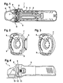
- Hand tool 1 shown is an angle grinder having an electric drive motor 2 in a motor housing 3, which is connected to a transmission housing 4.
- a gear not shown, is received, which is driven by the rotor of the electric drive motor and transmits the rotational movement of the rotor to a rotating tool.
- an air flow 5 is generated in the interior of the motor housing 3, which is guided along the drive motor and derived via an air guide element 6 from the housing.
- the air guide element 6 is constructed in two parts and comprises an air guide disc 7 and an air guide ring 8.
- Air guide disc 7 and air guide ring 8 are arranged in the transition region between the motor housing 3 and the transmission housing 4, wherein the air guide disc 7 is connected to the transmission housing 4 and the air guide ring 8 with the motor housing 3 , In the assembled position, the air-conducting element 6 and the air-guiding disk 7 interact, both components are in contact with one another, wherein a flow path for the discharge of the airflow 5 is formed between the components.
- FIGS. 2 and 3 As the perspective views of a spoiler 7 in the FIGS. 2 and 3 can be seen distributed over the circumference several individual functional portions 9 integrally formed with the air guide 7. Since the functional sections 9 extend into recesses in the housing, the functional sections 9 have a greater radial distance from the central axis than the remaining areas of the air-guiding disk.
- Fig. 4 The side view after Fig. 4 It can be seen that the functional portion 9 is positioned adjacent to the parting line 11 between the motor housing 3 and the gear housing 4.
- a recess 12 is introduced, wherein the shape of the recess 12 and the shape of the functional portion 9 are adapted to each other, so that the functional portion completely fills the recess 12.
- the recess 12 is located at a small distance to the dividing line 11 between the motor housing 3 and the transmission housing. 4
- the functional section 9 takes over in the exemplary embodiment Fig. 4 a design function, but possibly also an information function, for example, by printing information on the surface of the functional section.
- the functional portion 9 is formed integrally with the air guide element and consists in particular of the same material as the air guide element. But it is also possible a composite design in which the functional portion is made of a different material than the other parts of the air guide. For example, for the purpose of the switch protection of the functional portion may be made of a softer material, such as rubber or a rubber-like material to allow in the event of a fall of the power tool buffers a buffer.
- the functional element is designed as a damping element, which is arranged between the motor housing and the transmission housing and is intended to damp vibrations in the housing.
- the FIGS. 8 and 9 show a first embodiment, other variants are in the Figures 10 and 11 shown.
- the functional section is formed in two parts with a first part 9a and a second part 9b.
- Both functional sections 9a, 9b are annular and extend over the entire circumference of the angle grinder in the transition between the motor housing 3 and gear housing 4. In the lateral area, adjacent to the on / off switch 14, there is an axial extension in the functional section 9b, the is compensated by a corresponding shape of the other functional portion 9a, wherein the functional portion 9a seen over its circumference has a constant thickness.
- the functional section 9a is arranged on the gear housing 4 and the opposite functional section 9b on the motor housing 3.
- Each functional section belongs to a respective air-guiding element or a part of an air-guiding element.
- both functional sections 9a and 9b are of similar construction and have a constant thickness in the circumferential direction.
- the two functional sections 9a and 9b do not extend over the entire circumference, but are located only in the side region of the handheld power tool adjacent to the on / off switch 14. Both functional portions 9a, 9b are located in a recess which is introduced into the transmission housing 4.
- the function section 9 the task of slip protection to avoid that the hand of the operator accidentally slips off the handle of the power tool and slides in the direction of the rotating tool.
- FIGS. 15 and 16 takes over the function section 9, the task of an anti-rotation element to prevent mutual rotation of the motor housing 3 and the gear housing 4.
- a recess in the housing wall of both housing parts is introduced in the region of the parting line 11 between the motor housing 3 and the gear housing 4, which recess is jointly occupied by the functional section 9.
- the functional section 9 thus extends partly into the area of the motor housing 3 and partly into the area of the gear housing 4. As a result, a relative rotation between the two housing parts is made impossible.
- FIGS. 17 to 19 Another example of an anti-rotation is found in the FIGS. 17 to 19 ,
- the functional portion 9 is inserted into a recess in the motor housing 3 and has on its outer side a toothing, which cooperates with a lever 15 which is pivotally mounted on the upper side of the gear housing 4.
- This lever 15 is between the in Fig. 18 illustrated disengaged position and in Fig. 19 shown engaged position in which the lever 15 engages latching in the toothing on the outside of the functional portion 9.
- a relative rotation of the two housing parts 3 and 4 to each other can also be prevented.
- an additional axial locking can be realized, so that as seen in the axial direction, a release of the housing parts 3 and 4 is prevented from each other.
- Fig. 2 are different functional portions 9 distributed in the region of the transmission housing 4 distributed over the circumference.
- the function sections 9 assume the task of a pictogram, which is used to point to different functions of the angle grinder at different relative angular positions between the motor housing 3 and gear housing 4. For example, for use as a grinder another angular position may be useful than for use as a cutting device.
- Fig. 21 have the function sections 9, the task of air outlets over which the air flow is derived from the interior of the housing.
- the functional portions 9 are each provided with openings 16 which are connected to the housing interior, so that a continuous flow path for the air flow from the housing interior is given to the atmosphere.
- the air flow can be guided over the air outlets so that the exhaust air does not flow in the direction of the user, but for example, forward in the direction of the tool.
- a single functional portion 9 is provided on the upper side of the gear housing 4, wherein the functional portion 9 has an approximately triangular cross-section and an eyelet 17 is introduced into the functional portion.
- This eyelet 17 makes it possible to hang the power tool on a hook or the like or to secure using a padlock.
Landscapes
- Engineering & Computer Science (AREA)
- Mechanical Engineering (AREA)
- Finish Polishing, Edge Sharpening, And Grinding By Specific Grinding Devices (AREA)
- Sawing (AREA)
- Grinding-Machine Dressing And Accessory Apparatuses (AREA)
- Auxiliary Devices For Machine Tools (AREA)
- Motor Or Generator Frames (AREA)
Claims (10)
- Machine-outil, en particulier machine-outil manuelle, par exemple une meuleuse d'angle (1), comprenant un moteur d'entraînement (2) entraînant un outil (13) et un élément de guidage d'air (6) qui est disposé dans le boîtier en deux parties de la machine-outil (1) et qui guide vers l'extérieur un flux d'air (5) balayant le moteur d'entraînement (2), l'élément de guidage d'air (6) présentant une portion fonctionnelle (9) qui forme une partie de la surface d'enveloppe extérieure (10) de la machine-outil,
caractérisée en ce que l'élément de guidage d'air (6) est construit en deux parties et comprend une bague de guidage d'air (8) et un disque de guidage d'air (7), en ce que la portion fonctionnelle (9) de l'élément de guidage d'air (6) est disposée entre les parties du boîtier (3, 4) ou à côté de la ligne de séparation (11) entre les parties du boîtier (3, 4), et en ce que la bague de guidage d'air (8) est disposée dans la première partie du boîtier (3) et le disque de guidage d'air (7) est disposé dans la deuxième partie du boîtier (4). - Machine-outil selon la revendication 1, caractérisée en ce que la portion fonctionnelle (9) s'étend à travers un évidement (12) dans le boîtier.
- Machine-outil selon la revendication 1 ou 2, caractérisée en ce que la portion fonctionnelle (9) est insérée dans la surface d'enveloppe (10) du boîtier.
- Machine-outil selon l'une quelconque des revendications 1 à 3,
caractérisée en ce que la portion fonctionnelle (9) fait saillie au-dessus de la surface d'enveloppe (10) du boîtier. - Machine-outil selon l'une quelconque des revendications 1 à 4,
caractérisée en ce que la bague de guidage d'air (8) est en contact avec le disque de guidage d'air (7). - Machine-outil selon l'une quelconque des revendications 1 à 5,
caractérisée en ce qu'il est prévu plusieurs portions fonctionnelles (9) réparties sur la périphérie, pénétrant dans la surface d'enveloppe (10) ou formant la surface d'enveloppe (10). - Machine-outil selon l'une quelconque des revendications 1 à 6,
caractérisée en ce que les parties de boîtier sont formées par un boîtier de moteur (3) recevant le moteur d'entraînement (2) et par un boîtier de transmission (4) recevant une transmission. - Machine-outil selon l'une quelconque des revendications 1 à 7,
caractérisée en ce que la portion fonctionnelle (9) est réalisée sous forme d'élément de fixation contre la rotation des parties du boîtier (3, 4). - Machine-outil selon l'une quelconque des revendications 1 à 8,
caractérisée en ce que la portion fonctionnelle (9) est réalisée sous forme d'élément d'amortissement et est réalisée notamment sous forme de bague. - Machine-outil selon l'une quelconque des revendications 1 à 9,
caractérisée en ce que la portion fonctionnelle (9) est réalisée sous forme d'élément de sortie d'air et présente une ouverture de sortie d'air (16).
Applications Claiming Priority (2)
| Application Number | Priority Date | Filing Date | Title |
|---|---|---|---|
| DE102007017243A DE102007017243A1 (de) | 2007-04-12 | 2007-04-12 | Werkzeugmaschine, insbesondere Handwerkzeugmaschine |
| PCT/EP2008/051649 WO2008125368A1 (fr) | 2007-04-12 | 2008-02-12 | Machine-outil, notamment machine-outil manuelle |
Publications (3)
| Publication Number | Publication Date |
|---|---|
| EP2146820A1 EP2146820A1 (fr) | 2010-01-27 |
| EP2146820B1 true EP2146820B1 (fr) | 2011-07-13 |
| EP2146820B2 EP2146820B2 (fr) | 2019-10-16 |
Family
ID=39431175
Family Applications (1)
| Application Number | Title | Priority Date | Filing Date |
|---|---|---|---|
| EP08708891.0A Active EP2146820B2 (fr) | 2007-04-12 | 2008-02-12 | Machine-outil, notamment machine-outil manuelle |
Country Status (7)
| Country | Link |
|---|---|
| US (1) | US8113922B2 (fr) |
| EP (1) | EP2146820B2 (fr) |
| CN (1) | CN101657297B (fr) |
| AT (1) | ATE516112T1 (fr) |
| DE (1) | DE102007017243A1 (fr) |
| RU (1) | RU2472607C2 (fr) |
| WO (1) | WO2008125368A1 (fr) |
Families Citing this family (37)
| Publication number | Priority date | Publication date | Assignee | Title |
|---|---|---|---|---|
| DE102008059599A1 (de) * | 2008-11-28 | 2010-06-02 | Aeg Electric Tools Gmbh | Elektrowerkzeug |
| DE102008063510A1 (de) * | 2008-12-10 | 2010-06-17 | Flex-Elektrowerkzeuge Gmbh | Handgehaltene Werkzeugmaschine |
| WO2010087235A1 (fr) | 2009-01-30 | 2010-08-05 | Hitachi Koki Co., Ltd. | Outil électrique |
| DE102009026516A1 (de) | 2009-05-27 | 2010-12-02 | Robert Bosch Gmbh | Werkzeugmaschine, insbesondere Handwerkzeugmaschine |
| DE102009026519A1 (de) | 2009-05-27 | 2010-12-02 | Robert Bosch Gmbh | Werkzeugmaschine, insbesondere Handwerkzeugmaschine |
| JP5395531B2 (ja) * | 2009-06-19 | 2014-01-22 | 株式会社マキタ | 作業工具 |
| DE202011001475U1 (de) * | 2011-01-13 | 2011-03-17 | Metabowerke Gmbh | Elektrowerkzeugmaschine, insbesondere eine Schleif- oder Poliermaschine |
| US8348727B2 (en) * | 2011-05-26 | 2013-01-08 | Black & Decker Inc. | Airflow arrangement for a power tool |
| DE102012103603A1 (de) | 2012-04-24 | 2013-10-24 | C. & E. Fein Gmbh | Handführbare Werkzeugmaschine mit Lüftereinrichtung |
| US20130299207A1 (en) * | 2012-05-10 | 2013-11-14 | Black & Decker, Inc. | Power tool cooling |
| DE102012223897A1 (de) * | 2012-12-20 | 2014-06-26 | Robert Bosch Gmbh | Handwerkzeugmaschine |
| DE102013219450A1 (de) * | 2013-09-26 | 2015-03-26 | Robert Bosch Gmbh | Batteriebetriebener Exzenterschleifer mit einem elektronisch kommutierten Elektromotor |
| USD725981S1 (en) | 2013-10-29 | 2015-04-07 | Black & Decker Inc. | Screwdriver with nosepiece |
| US20150151424A1 (en) | 2013-10-29 | 2015-06-04 | Black & Decker Inc. | Power tool with ergonomic handgrip |
| US9954418B2 (en) | 2014-03-17 | 2018-04-24 | Makita Corporation | Power tool |
| EP2946887B1 (fr) * | 2014-05-20 | 2017-08-23 | Black & Decker Inc. | Ensemble de séparation de particules pour un outil électrique |
| DE102014210915A1 (de) * | 2014-06-06 | 2015-12-17 | Robert Bosch Gmbh | Elektrowerkzeugmaschine |
| US9475172B2 (en) | 2014-07-15 | 2016-10-25 | Milwaukee Electric Tool Corporation | Adjustable guard for power tool |
| GB201413008D0 (en) * | 2014-07-23 | 2014-09-03 | Black & Decker Inc | A range of power tools |
| DE102015111717A1 (de) * | 2015-07-20 | 2017-01-26 | Metabowerke Gmbh | Luftleitscheibe |
| JP6646373B2 (ja) * | 2015-07-23 | 2020-02-14 | 京セラインダストリアルツールズ株式会社 | 手持ち式電動工具 |
| EP3357645B1 (fr) * | 2016-02-19 | 2019-11-27 | Makita Corporation | Outil de travail |
| DE102016210853A1 (de) * | 2016-06-17 | 2017-12-21 | Robert Bosch Gmbh | Handwerkzeugmaschine mit einer Kühleinheit |
| DE202018104460U1 (de) * | 2017-09-29 | 2018-08-16 | Nanjing Chervon Industry Co., Ltd. | Elektrohandwerkzeug |
| DE102018208048A1 (de) * | 2018-05-23 | 2019-11-28 | Robert Bosch Gmbh | Handwerkzeugmaschine |
| EP3603898B1 (fr) * | 2018-08-03 | 2021-04-14 | Andreas Stihl AG & Co. KG | Appareil de travail portatif |
| DE102018217155A1 (de) * | 2018-10-08 | 2020-04-09 | Robert Bosch Gmbh | Handwerkzeugmaschine |
| JP7210261B2 (ja) | 2018-12-14 | 2023-01-23 | 株式会社マキタ | 電動作業機及び電動作業機用モータにおけるステータの製造方法 |
| SE543413C2 (en) * | 2019-05-03 | 2021-01-05 | Husqvarna Ab | Hand-held electrically powered device |
| DE202019106969U1 (de) * | 2019-12-13 | 2021-03-16 | C. & E. Fein Gmbh | Elektrische Handwerkzeugmaschine |
| DE202019106967U1 (de) * | 2019-12-13 | 2021-03-16 | C. & E. Fein Gmbh | Elektrische Handwerkzeugmaschine |
| DE102019220625A1 (de) * | 2019-12-30 | 2021-07-01 | Robert Bosch Gmbh | Handwerkzeugmaschinenvorrichtung, Handwerkzeugmaschine mit der Handwerkzeugmaschinenvorrichtung und Zubehör mit der Handwerkzeugmaschinenvorrichtung |
| DE102020214817A1 (de) | 2019-12-30 | 2021-07-01 | Robert Bosch Gesellschaft mit beschränkter Haftung | Werkzeugmaschine und Verfahren zu einem Kühlen einer Antriebseinheit der Werkzeugmaschine |
| CN113560664A (zh) * | 2020-04-28 | 2021-10-29 | 南京德朔实业有限公司 | 电圆锯 |
| US12233523B2 (en) | 2020-12-07 | 2025-02-25 | Black & Decker Inc. | Power tool with multiple modes of operation and ergonomic handgrip |
| DE102022134161A1 (de) * | 2021-12-22 | 2023-06-22 | Festool Gmbh | Hand-Werkzeugmaschine mit in Winkelpositionen montierbarem Handgriffgehäuseteil |
| DE102023206273A1 (de) * | 2022-07-19 | 2024-01-25 | Robert Bosch Gesellschaft mit beschränkter Haftung | Werkzeugmaschinenvorrichtung, Werkzeugmaschine und Verfahren zu einem Betrieb einer Werkzeugmaschine |
Family Cites Families (17)
| Publication number | Priority date | Publication date | Assignee | Title |
|---|---|---|---|---|
| NL277215A (fr) † | 1961-04-14 | |||
| US3829721A (en) * | 1973-07-30 | 1974-08-13 | Black & Decker Mfg Co | Air flow baffle construction for electric motor devices |
| DE2910845A1 (de) | 1979-03-20 | 1980-10-02 | Bosch Gmbh Robert | Elektrisch angetriebenes handwerkzeug, insbesondere bohrmaschine |
| US4905772A (en) * | 1988-09-01 | 1990-03-06 | Honsa Thomas W | Rotary power tool with vibration damping |
| DE4003029A1 (de) * | 1990-02-02 | 1991-08-08 | Bosch Gmbh Robert | Handgefuehrte werkzeugmaschine mit radialgeblaese |
| DE4220078A1 (de) * | 1992-06-19 | 1993-12-23 | Bosch Gmbh Robert | Handwerkzeugmaschine |
| DE29501974U1 (de) | 1995-02-08 | 1996-06-05 | Robert Bosch Gmbh, 70469 Stuttgart | Elektrohandwerkzeugmaschine |
| DE29513331U1 (de) * | 1995-08-19 | 1996-12-12 | Robert Bosch Gmbh, 70469 Stuttgart | Winkelschleiferschutzhaube |
| ATE287319T1 (de) * | 1998-12-31 | 2005-02-15 | Fein C & E Gmbh | Elektrowerkzeug, insbesondere winkelschleifer |
| DE19924552A1 (de) * | 1999-05-28 | 2000-11-30 | Hilti Ag | Elektrisch betreibbares Handgerät |
| CN1136491C (zh) * | 2000-11-23 | 2004-01-28 | 厦门资盛科技发展有限公司 | 单机多人使用的多工接口卡 |
| DE10248921A1 (de) * | 2002-10-17 | 2004-05-13 | C. & E. Fein Gmbh & Co Kg | Elektrowerkzeug |
| DE10261572A1 (de) * | 2002-12-23 | 2004-07-01 | Robert Bosch Gmbh | Elektrohandwerkzeugmaschine |
| JP4731162B2 (ja) † | 2004-12-27 | 2011-07-20 | 株式会社マキタ | 電動工具 |
| JP4575223B2 (ja) * | 2005-04-20 | 2010-11-04 | 株式会社マキタ | 回転工具 |
| US7988538B2 (en) * | 2006-10-13 | 2011-08-02 | Black & Decker Inc. | Large angle grinder |
| US7770660B2 (en) * | 2007-11-21 | 2010-08-10 | Black & Decker Inc. | Mid-handle drill construction and assembly process |
-
2007
- 2007-04-12 DE DE102007017243A patent/DE102007017243A1/de not_active Withdrawn
-
2008
- 2008-02-12 AT AT08708891T patent/ATE516112T1/de active
- 2008-02-12 EP EP08708891.0A patent/EP2146820B2/fr active Active
- 2008-02-12 US US12/307,649 patent/US8113922B2/en active Active
- 2008-02-12 WO PCT/EP2008/051649 patent/WO2008125368A1/fr not_active Ceased
- 2008-02-12 CN CN2008800118576A patent/CN101657297B/zh active Active
- 2008-02-12 RU RU2009141525/02A patent/RU2472607C2/ru active
Also Published As
| Publication number | Publication date |
|---|---|
| EP2146820A1 (fr) | 2010-01-27 |
| DE102007017243A1 (de) | 2008-10-16 |
| EP2146820B2 (fr) | 2019-10-16 |
| ATE516112T1 (de) | 2011-07-15 |
| RU2009141525A (ru) | 2011-05-20 |
| WO2008125368A1 (fr) | 2008-10-23 |
| CN101657297B (zh) | 2013-03-06 |
| US8113922B2 (en) | 2012-02-14 |
| RU2472607C2 (ru) | 2013-01-20 |
| US20090280732A1 (en) | 2009-11-12 |
| CN101657297A (zh) | 2010-02-24 |
Similar Documents
| Publication | Publication Date | Title |
|---|---|---|
| EP2146820B1 (fr) | Machine-outil, notamment machine-outil manuelle | |
| DE112007003732B4 (de) | Schneid- oder Sägemaschine | |
| EP2086372B1 (fr) | Dispositif d'entraînement pour des éléments mobiles de meubles | |
| EP2101957B1 (fr) | Appareil électrique avec élément de commande rotatif à emboîtement | |
| DE102012004037B4 (de) | Arbeitsgerät | |
| DE102016111028B4 (de) | Staubsammelabdeckung für Schneidevorrichtungen | |
| EP3022998A1 (fr) | Appareil de travail portatif | |
| DE4032176C2 (de) | Scheibenschneider | |
| EP2476520B1 (fr) | Machine-outil électrique, notamment une machine de ponçage ou de polissage | |
| DE102016111548A1 (de) | Bearbeitungsvorrichtung | |
| EP2944433A1 (fr) | Machine-outil portative | |
| EP2987577A1 (fr) | Scie a guichet | |
| EP1029436A2 (fr) | Fixation, faucheuse et véhicule resp. appareil de travail | |
| EP3389952B1 (fr) | Machine-outil iii sur batterie | |
| EP2677910B1 (fr) | Outil et dispositif d'entraînement pour appareil de cuisine commandé par un moteur | |
| DE102008000732A1 (de) | Handwerkzeugmaschine, insbesondere handgeführte Schleifmaschine | |
| EP2125279B1 (fr) | Dispositif séparateur de tuyaux | |
| DE10318324A1 (de) | Kantenschneider | |
| EP0458080B1 (fr) | Machine-outil électrique pour manipulation manuelle | |
| DE102005063016A1 (de) | Handwerkzeugmaschine mit Drehgriffverstelleinrichtung | |
| DE102019105567A1 (de) | Drehmomentwerkzeug | |
| DE102008001829A1 (de) | Handwerkzeugmaschine, insbesondere Akku-Schrauber bzw. Akku-Bohrer | |
| EP2472679A1 (fr) | Dispositif de brosse dans une installation de commutateur dans une machine électrique | |
| DE102015111717A1 (de) | Luftleitscheibe | |
| DE102024111417B4 (de) | Handgeführtes Arbeitsgerät mit Schutzhaube |
Legal Events
| Date | Code | Title | Description |
|---|---|---|---|
| PUAI | Public reference made under article 153(3) epc to a published international application that has entered the european phase |
Free format text: ORIGINAL CODE: 0009012 |
|
| 17P | Request for examination filed |
Effective date: 20091112 |
|
| AK | Designated contracting states |
Kind code of ref document: A1 Designated state(s): AT BE BG CH CY CZ DE DK EE ES FI FR GB GR HR HU IE IS IT LI LT LU LV MC MT NL NO PL PT RO SE SI SK TR |
|
| AX | Request for extension of the european patent |
Extension state: AL BA MK RS |
|
| DAX | Request for extension of the european patent (deleted) | ||
| 17Q | First examination report despatched |
Effective date: 20100716 |
|
| GRAP | Despatch of communication of intention to grant a patent |
Free format text: ORIGINAL CODE: EPIDOSNIGR1 |
|
| GRAS | Grant fee paid |
Free format text: ORIGINAL CODE: EPIDOSNIGR3 |
|
| GRAA | (expected) grant |
Free format text: ORIGINAL CODE: 0009210 |
|
| AK | Designated contracting states |
Kind code of ref document: B1 Designated state(s): AT BE BG CH CY CZ DE DK EE ES FI FR GB GR HR HU IE IS IT LI LT LU LV MC MT NL NO PL PT RO SE SI SK TR |
|
| REG | Reference to a national code |
Ref country code: GB Ref legal event code: FG4D Free format text: NOT ENGLISH |
|
| REG | Reference to a national code |
Ref country code: CH Ref legal event code: EP |
|
| REG | Reference to a national code |
Ref country code: IE Ref legal event code: FG4D Free format text: LANGUAGE OF EP DOCUMENT: GERMAN |
|
| REG | Reference to a national code |
Ref country code: DE Ref legal event code: R096 Ref document number: 502008004187 Country of ref document: DE Effective date: 20110908 |
|
| REG | Reference to a national code |
Ref country code: NL Ref legal event code: VDEP Effective date: 20110713 |
|
| PG25 | Lapsed in a contracting state [announced via postgrant information from national office to epo] |
Ref country code: PT Free format text: LAPSE BECAUSE OF FAILURE TO SUBMIT A TRANSLATION OF THE DESCRIPTION OR TO PAY THE FEE WITHIN THE PRESCRIBED TIME-LIMIT Effective date: 20111114 Ref country code: LT Free format text: LAPSE BECAUSE OF FAILURE TO SUBMIT A TRANSLATION OF THE DESCRIPTION OR TO PAY THE FEE WITHIN THE PRESCRIBED TIME-LIMIT Effective date: 20110713 Ref country code: IS Free format text: LAPSE BECAUSE OF FAILURE TO SUBMIT A TRANSLATION OF THE DESCRIPTION OR TO PAY THE FEE WITHIN THE PRESCRIBED TIME-LIMIT Effective date: 20111113 Ref country code: NO Free format text: LAPSE BECAUSE OF FAILURE TO SUBMIT A TRANSLATION OF THE DESCRIPTION OR TO PAY THE FEE WITHIN THE PRESCRIBED TIME-LIMIT Effective date: 20111013 Ref country code: FI Free format text: LAPSE BECAUSE OF FAILURE TO SUBMIT A TRANSLATION OF THE DESCRIPTION OR TO PAY THE FEE WITHIN THE PRESCRIBED TIME-LIMIT Effective date: 20110713 Ref country code: HR Free format text: LAPSE BECAUSE OF FAILURE TO SUBMIT A TRANSLATION OF THE DESCRIPTION OR TO PAY THE FEE WITHIN THE PRESCRIBED TIME-LIMIT Effective date: 20110713 Ref country code: NL Free format text: LAPSE BECAUSE OF FAILURE TO SUBMIT A TRANSLATION OF THE DESCRIPTION OR TO PAY THE FEE WITHIN THE PRESCRIBED TIME-LIMIT Effective date: 20110713 Ref country code: SE Free format text: LAPSE BECAUSE OF FAILURE TO SUBMIT A TRANSLATION OF THE DESCRIPTION OR TO PAY THE FEE WITHIN THE PRESCRIBED TIME-LIMIT Effective date: 20110713 |
|
| REG | Reference to a national code |
Ref country code: IE Ref legal event code: FD4D |
|
| PG25 | Lapsed in a contracting state [announced via postgrant information from national office to epo] |
Ref country code: CY Free format text: LAPSE BECAUSE OF FAILURE TO SUBMIT A TRANSLATION OF THE DESCRIPTION OR TO PAY THE FEE WITHIN THE PRESCRIBED TIME-LIMIT Effective date: 20110713 Ref country code: SI Free format text: LAPSE BECAUSE OF FAILURE TO SUBMIT A TRANSLATION OF THE DESCRIPTION OR TO PAY THE FEE WITHIN THE PRESCRIBED TIME-LIMIT Effective date: 20110713 Ref country code: LV Free format text: LAPSE BECAUSE OF FAILURE TO SUBMIT A TRANSLATION OF THE DESCRIPTION OR TO PAY THE FEE WITHIN THE PRESCRIBED TIME-LIMIT Effective date: 20110713 Ref country code: GR Free format text: LAPSE BECAUSE OF FAILURE TO SUBMIT A TRANSLATION OF THE DESCRIPTION OR TO PAY THE FEE WITHIN THE PRESCRIBED TIME-LIMIT Effective date: 20111014 Ref country code: PL Free format text: LAPSE BECAUSE OF FAILURE TO SUBMIT A TRANSLATION OF THE DESCRIPTION OR TO PAY THE FEE WITHIN THE PRESCRIBED TIME-LIMIT Effective date: 20110713 |
|
| PLBI | Opposition filed |
Free format text: ORIGINAL CODE: 0009260 |
|
| PG25 | Lapsed in a contracting state [announced via postgrant information from national office to epo] |
Ref country code: SK Free format text: LAPSE BECAUSE OF FAILURE TO SUBMIT A TRANSLATION OF THE DESCRIPTION OR TO PAY THE FEE WITHIN THE PRESCRIBED TIME-LIMIT Effective date: 20110713 Ref country code: CZ Free format text: LAPSE BECAUSE OF FAILURE TO SUBMIT A TRANSLATION OF THE DESCRIPTION OR TO PAY THE FEE WITHIN THE PRESCRIBED TIME-LIMIT Effective date: 20110713 Ref country code: IE Free format text: LAPSE BECAUSE OF FAILURE TO SUBMIT A TRANSLATION OF THE DESCRIPTION OR TO PAY THE FEE WITHIN THE PRESCRIBED TIME-LIMIT Effective date: 20110713 |
|
| PLAX | Notice of opposition and request to file observation + time limit sent |
Free format text: ORIGINAL CODE: EPIDOSNOBS2 |
|
| 26 | Opposition filed |
Opponent name: METABOWERKE GMBH Effective date: 20120413 |
|
| PG25 | Lapsed in a contracting state [announced via postgrant information from national office to epo] |
Ref country code: RO Free format text: LAPSE BECAUSE OF FAILURE TO SUBMIT A TRANSLATION OF THE DESCRIPTION OR TO PAY THE FEE WITHIN THE PRESCRIBED TIME-LIMIT Effective date: 20110713 Ref country code: EE Free format text: LAPSE BECAUSE OF FAILURE TO SUBMIT A TRANSLATION OF THE DESCRIPTION OR TO PAY THE FEE WITHIN THE PRESCRIBED TIME-LIMIT Effective date: 20110713 Ref country code: IT Free format text: LAPSE BECAUSE OF FAILURE TO SUBMIT A TRANSLATION OF THE DESCRIPTION OR TO PAY THE FEE WITHIN THE PRESCRIBED TIME-LIMIT Effective date: 20110713 |
|
| PG25 | Lapsed in a contracting state [announced via postgrant information from national office to epo] |
Ref country code: DK Free format text: LAPSE BECAUSE OF FAILURE TO SUBMIT A TRANSLATION OF THE DESCRIPTION OR TO PAY THE FEE WITHIN THE PRESCRIBED TIME-LIMIT Effective date: 20110713 |
|
| REG | Reference to a national code |
Ref country code: DE Ref legal event code: R026 Ref document number: 502008004187 Country of ref document: DE Effective date: 20120413 |
|
| BERE | Be: lapsed |
Owner name: ROBERT BOSCH G.M.B.H. Effective date: 20120228 |
|
| PG25 | Lapsed in a contracting state [announced via postgrant information from national office to epo] |
Ref country code: MC Free format text: LAPSE BECAUSE OF NON-PAYMENT OF DUE FEES Effective date: 20120229 |
|
| REG | Reference to a national code |
Ref country code: CH Ref legal event code: PL |
|
| PLBB | Reply of patent proprietor to notice(s) of opposition received |
Free format text: ORIGINAL CODE: EPIDOSNOBS3 |
|
| PG25 | Lapsed in a contracting state [announced via postgrant information from national office to epo] |
Ref country code: LI Free format text: LAPSE BECAUSE OF NON-PAYMENT OF DUE FEES Effective date: 20120229 Ref country code: CH Free format text: LAPSE BECAUSE OF NON-PAYMENT OF DUE FEES Effective date: 20120229 |
|
| PG25 | Lapsed in a contracting state [announced via postgrant information from national office to epo] |
Ref country code: BE Free format text: LAPSE BECAUSE OF NON-PAYMENT OF DUE FEES Effective date: 20120228 |
|
| PG25 | Lapsed in a contracting state [announced via postgrant information from national office to epo] |
Ref country code: ES Free format text: LAPSE BECAUSE OF FAILURE TO SUBMIT A TRANSLATION OF THE DESCRIPTION OR TO PAY THE FEE WITHIN THE PRESCRIBED TIME-LIMIT Effective date: 20111024 |
|
| PG25 | Lapsed in a contracting state [announced via postgrant information from national office to epo] |
Ref country code: BG Free format text: LAPSE BECAUSE OF FAILURE TO SUBMIT A TRANSLATION OF THE DESCRIPTION OR TO PAY THE FEE WITHIN THE PRESCRIBED TIME-LIMIT Effective date: 20111013 |
|
| PG25 | Lapsed in a contracting state [announced via postgrant information from national office to epo] |
Ref country code: MT Free format text: LAPSE BECAUSE OF FAILURE TO SUBMIT A TRANSLATION OF THE DESCRIPTION OR TO PAY THE FEE WITHIN THE PRESCRIBED TIME-LIMIT Effective date: 20110713 |
|
| REG | Reference to a national code |
Ref country code: AT Ref legal event code: MM01 Ref document number: 516112 Country of ref document: AT Kind code of ref document: T Effective date: 20130212 |
|
| PG25 | Lapsed in a contracting state [announced via postgrant information from national office to epo] |
Ref country code: TR Free format text: LAPSE BECAUSE OF FAILURE TO SUBMIT A TRANSLATION OF THE DESCRIPTION OR TO PAY THE FEE WITHIN THE PRESCRIBED TIME-LIMIT Effective date: 20110713 |
|
| PG25 | Lapsed in a contracting state [announced via postgrant information from national office to epo] |
Ref country code: LU Free format text: LAPSE BECAUSE OF NON-PAYMENT OF DUE FEES Effective date: 20120212 Ref country code: AT Free format text: LAPSE BECAUSE OF NON-PAYMENT OF DUE FEES Effective date: 20130212 |
|
| PG25 | Lapsed in a contracting state [announced via postgrant information from national office to epo] |
Ref country code: HU Free format text: LAPSE BECAUSE OF FAILURE TO SUBMIT A TRANSLATION OF THE DESCRIPTION OR TO PAY THE FEE WITHIN THE PRESCRIBED TIME-LIMIT Effective date: 20080212 |
|
| APAH | Appeal reference modified |
Free format text: ORIGINAL CODE: EPIDOSCREFNO |
|
| APBM | Appeal reference recorded |
Free format text: ORIGINAL CODE: EPIDOSNREFNO |
|
| APBP | Date of receipt of notice of appeal recorded |
Free format text: ORIGINAL CODE: EPIDOSNNOA2O |
|
| APBM | Appeal reference recorded |
Free format text: ORIGINAL CODE: EPIDOSNREFNO |
|
| APBP | Date of receipt of notice of appeal recorded |
Free format text: ORIGINAL CODE: EPIDOSNNOA2O |
|
| APBQ | Date of receipt of statement of grounds of appeal recorded |
Free format text: ORIGINAL CODE: EPIDOSNNOA3O |
|
| APBQ | Date of receipt of statement of grounds of appeal recorded |
Free format text: ORIGINAL CODE: EPIDOSNNOA3O |
|
| REG | Reference to a national code |
Ref country code: FR Ref legal event code: PLFP Year of fee payment: 9 |
|
| REG | Reference to a national code |
Ref country code: FR Ref legal event code: PLFP Year of fee payment: 10 |
|
| REG | Reference to a national code |
Ref country code: FR Ref legal event code: PLFP Year of fee payment: 11 |
|
| PLBP | Opposition withdrawn |
Free format text: ORIGINAL CODE: 0009264 |
|
| APBU | Appeal procedure closed |
Free format text: ORIGINAL CODE: EPIDOSNNOA9O |
|
| PUAH | Patent maintained in amended form |
Free format text: ORIGINAL CODE: 0009272 |
|
| STAA | Information on the status of an ep patent application or granted ep patent |
Free format text: STATUS: PATENT MAINTAINED AS AMENDED |
|
| 27A | Patent maintained in amended form |
Effective date: 20191016 |
|
| AK | Designated contracting states |
Kind code of ref document: B2 Designated state(s): AT BE BG CH CY CZ DE DK EE ES FI FR GB GR HR HU IE IS IT LI LT LU LV MC MT NL NO PL PT RO SE SI SK TR |
|
| REG | Reference to a national code |
Ref country code: DE Ref legal event code: R102 Ref document number: 502008004187 Country of ref document: DE |
|
| PGFP | Annual fee paid to national office [announced via postgrant information from national office to epo] |
Ref country code: GB Payment date: 20200225 Year of fee payment: 13 |
|
| GBPC | Gb: european patent ceased through non-payment of renewal fee |
Effective date: 20210212 |
|
| PG25 | Lapsed in a contracting state [announced via postgrant information from national office to epo] |
Ref country code: GB Free format text: LAPSE BECAUSE OF NON-PAYMENT OF DUE FEES Effective date: 20210212 |
|
| P01 | Opt-out of the competence of the unified patent court (upc) registered |
Effective date: 20230509 |
|
| PGFP | Annual fee paid to national office [announced via postgrant information from national office to epo] |
Ref country code: DE Payment date: 20250422 Year of fee payment: 18 |
|
| PGFP | Annual fee paid to national office [announced via postgrant information from national office to epo] |
Ref country code: FR Payment date: 20260219 Year of fee payment: 19 |