EP2147126B1 - Schwenkarmstanze - Google Patents
Schwenkarmstanze Download PDFInfo
- Publication number
- EP2147126B1 EP2147126B1 EP07736781A EP07736781A EP2147126B1 EP 2147126 B1 EP2147126 B1 EP 2147126B1 EP 07736781 A EP07736781 A EP 07736781A EP 07736781 A EP07736781 A EP 07736781A EP 2147126 B1 EP2147126 B1 EP 2147126B1
- Authority
- EP
- European Patent Office
- Prior art keywords
- arm
- plane
- press according
- clicking
- pressing
- Prior art date
- Legal status (The legal status is an assumption and is not a legal conclusion. Google has not performed a legal analysis and makes no representation as to the accuracy of the status listed.)
- Not-in-force
Links
- 238000003825 pressing Methods 0.000 claims abstract description 50
- 230000000903 blocking effect Effects 0.000 claims abstract description 18
- 230000003014 reinforcing effect Effects 0.000 claims description 3
- 238000012545 processing Methods 0.000 description 6
- 238000007792 addition Methods 0.000 description 1
- -1 hides Substances 0.000 description 1
- 239000010985 leather Substances 0.000 description 1
- 238000004519 manufacturing process Methods 0.000 description 1
- 238000000034 method Methods 0.000 description 1
Images

Classifications
-
- C—CHEMISTRY; METALLURGY
- C14—SKINS; HIDES; PELTS; LEATHER
- C14B—MECHANICAL TREATMENT OR PROCESSING OF SKINS, HIDES OR LEATHER IN GENERAL; PELT-SHEARING MACHINES; INTESTINE-SPLITTING MACHINES
- C14B5/00—Clicking, perforating, or cutting leather
-
- B—PERFORMING OPERATIONS; TRANSPORTING
- B26—HAND CUTTING TOOLS; CUTTING; SEVERING
- B26F—PERFORATING; PUNCHING; CUTTING-OUT; STAMPING-OUT; SEVERING BY MEANS OTHER THAN CUTTING
- B26F1/00—Perforating; Punching; Cutting-out; Stamping-out; Apparatus therefor
- B26F1/38—Cutting-out; Stamping-out
- B26F1/40—Cutting-out; Stamping-out using a press, e.g. of the ram type
Definitions
- the present invention relates to a clicking press for processing leather, hides, rubber and the like and in particular a turning arm clicking press (see for example DE-A-35 46 250 ).
- Turning arm clicking presses generally comprise a base on the top of which a working plane is arranged allowing to place a work piece and the tool or tools provided for the processing.
- the base is provided with a vertical support on which an arm is arranged supporting a pressing plane substantially parallel to the working plane.
- the support is movable in the vertical direction and driven by driving means arranged inside the base such as, for example, a hydraulic servomechanism, and the turning arm is rotatable relative to the base around a substantially vertical axis.
- the arm In order to carry out a clicking operation, the arm is so rotated to place the pressing plane over the work piece and the tools arranged on the working plane, then the support is driven pressing with a given force the pressing plane on the tools and the work piece, and finally the support is driven in the opposite direction in order to move the working plane away and thus enable the rotation of the turning arm and the access to the working plane for the removal of the work piece.
- Turning arm clicking presses are extremely practical and inexpensive machines, however they exhibit the drawback of having pressing planes of a much lower size with respect to the size of the working plane and such to not allow to exploit their whole area even by rotating the pressing plane in several positions by means of the turning arm. This results in a remarkable limit to the size of the pieces processable on this type of machines.
- the rotation of the turning arm in order to try to cover more zones of the working plane during the processing of a work piece often results in a low quality of the processing.
- the turning arm clicking press is provided with rotation blocking means that define a working position of the turning arm in which the pressing plane is substantially overlapped with the working plane.
- the pressing plane is longitudinally slidable relative to the turning arm and has a size substantially corresponding to the size of the working plane.
- the main advantage of the clicking press according to the present invention is that through a single precise and repeatable positioning of the turning arm and a single driving of the pressing plane, it is possible to entirely cover the surface of the working plane, thus being able to process work pieces of a larger size with respect to the work pieces that can be processed on clicking presses of a similar size and to obtain processings with a high and uniform quality.
- the possibility of making the pressing plane slide relative to the turning arm makes it possible to access the working plane with neither the need of rotating each time the turning arm, nor the need of positioning it again for the subsequent processing, resulting in remarkable time savings, especially in the case of mass production.
- the sliding of the pressing plane relative to the turning arm may be driven both manually and automatically, thus providing the user with the maximum ease of handling in any situation.
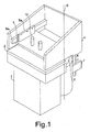
- the clicking press comprises in a known way a base 1 on the top of which a working plane 2 is arranged.
- the base is provided with a vertical support 3 on which an arm 4 is fixed supporting a pressing plane 5 substantially parallel to the working plane 2.
- the support 3 is movable in the vertical direction and is driven by driving means arranged inside base 1, a hydraulic servomechanism for instance, in order to carry out a clicking operation and arm 4 is rotatable relative to base 1 around a substantially vertical axis 6.
- the clicking press also includes blocking means of arm 4, comprising a first blocking element 7 arranged on base 1 and a second blocking element 8 arranged on arm 4.
- the first and the second blocking elements are suitable to engage one in the other, thus defining a working position of arm 4 wherein the pressing plane 5 is substantially overlapped with the working plane 2.
- the pressing plane 5 is longitudinally slidable relative to arm 4, in order to enable the access to the working plane 2 between one clicking operation and the following one.
- the first blocking element may be, for instance, a fork 7 fixed to base 1 and arranged in proximity to support 3, and the second blocking element may be, for instance, a vertical rod 8 fixed to arm 4, which rod engages fork 7 in the working position.
- the pressing plane 5 has a size substantially corresponding to those of the working plane 2, for example typically 900x450 mm, 1000x500 mm or 1200x500 mm.
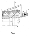
- the arm 4 comprises two side walls 4a, 4b that are respectively provided with longitudinal guides 9a, 9b and the pressing plane 5 is slidable therealong by means of a pair of vertical supports 5a, 5b arranged in proximity to its opposite side edges and provided with bearing means 10a, 10b.
- the bearing means 10a, 10b are ball bearings.
- the pressing plane 5 is arranged under the longitudinal guides 9a, 9b, substantially contacting their lower surfaces.
- the pressing load is transmitted from arm 4 to the pressing plane 5 through the longitudinal guides 9a, 9b.
- the sliding of the pressing plane 5 relative to arm 4 is limited between a first and a second stop arranged on the longitudinal guides 9a, 9b.
- the pressing plane 5 preferably further comprises centering means 11 a, 11b arranged on the vertical supports 5a, 5b. and slidable on the lateral surfaces of the longitudinal guides 9a, 9b.
- the centering means 11a, 11b may comprise, for example, ball bearings urged against the longitudinal guides 9a, 9b by elastic means such as, for instance, Belleville springs, and serve to ensure the alignment of the pressing plane 5 with respect to the working plane 2 in the transverse direction.
- the pressing plane 5 may be manually slid by acting upon pair of handles 12 arranged thereon and generally comprising the pressing drives of the clicking press.
- the sliding of the pressing plane may be automatically driven by means of a servomechanism such as, for example, a gearmotor and a worm.
- gearmotor 13 is arranged provided on the output shaft with a worm 14 fitted in a threaded collar 15, which is arranged in the back portion of the pressing plane 5.
- the driving of gearmotor 13 generates a rotation of worm 14, which determines a sliding of the pressing plane 5 between the two end-stroke positions by means of the threaded collar 15.
- the drive of servomechanism 13, 14, 15 may be advantageously arranged in the driving handles 12 fixed on the pressing plane 5 and position sensors, suitable to automatically block the pressing plane 5, may be placed at the end-stroke locations.
- the side walls 4a, 4b of arm 4 may be provided with a truss structure made up of struts and tie rods, which provides arm 4 with a high flexural rigidity while maintaining at the same time a low weight of the structure.
- transverse reinforcing elements may be arranged between the side walls 4a, 4b, suitable to provide arm 4 with an improved torsional rigidity, thus enabling arm 4 to withstand, without being deformed, pressing loads being higher than those of known turning arm clicking presses and typical of clicking presses of larger size.
Landscapes
- Engineering & Computer Science (AREA)
- Mechanical Engineering (AREA)
- Life Sciences & Earth Sciences (AREA)
- Forests & Forestry (AREA)
- Chemical & Material Sciences (AREA)
- Organic Chemistry (AREA)
- Press Drives And Press Lines (AREA)
- Glass Compositions (AREA)
- Seal Device For Vehicle (AREA)
- Devices For Conveying Motion By Means Of Endless Flexible Members (AREA)
- Presses And Accessory Devices Thereof (AREA)
Claims (16)
- Schwenkarmstanze, umfassend ein Unterteil (1), auf dessen Oberseite eine Arbeitsebene (2) angeordnet ist, wobei das besagte Unterteil (1) mit einer vertikalen Stütze (3) versehen ist, worauf ein Arm (4) aufgebaut ist, der eine Pressebene (5) im Wesentlichen parallel zu der Arbeitsebene (2) trägt, wobei die Stütze (3) in vertikaler Richtung bewegbar ist mittels Antriebsmittel, welche innerhalb des Unterteils (1) angeordnet sind, und wobei der besagte Arm (4) relativ zu dem Unterteil (1) um eine im Wesentlichen vertikale Achse (6) schwenkbar ist, ferner gekennzeichnet durch Blockiermittel (7, 8) des Arms (4), wobei besagte Blockiermittel (7, 8) ein erstes, an dem Unterteil (1) angeordetes Blockierelement (7) aufweisen, sowie ein zweites, an dem Arm (4) angeordnetes Blockierelement (8), und wobei besagtes erstes und zweites Blockierelement (7, 8) geeignet sind, ineinander einzugreifen, um eine Arbeitsposition des Arms (4) zu definieren, in welcher sich die Pressebene (5) mit der Arbeitsebene (2) im Wesentlichen überdeckt, und wobei die Pressebene (5) relativ zu dem Arm (4) longitudinal verschiebbar ist, um den Zugang zu der Arbeitsebene (2) zwischen einer Stanzoperation und der folgenden zu ermöglichen.
- Schwenkarmstanze nach dem vorhergehenden Anspruch, dadurch gekennzeichnet, dass das besagte, erste Blockierelement (7) eine an dem Unterteil (1) befestigte und in der Nähe der Stütze (3) angeordnete Gabel ist, und dass das besagte, zweite Blockierelement (8) eine an dem Arm (4) befestigte, vertikale Stange ist, wobei die besagte, vertikale Stange (8) in der Lage ist, in besagter Arbeitsposition in die Gabel (7) einzugreifen.
- Schwenkarmstanze nach einem der vorhergehenden Ansprüche, dadurch gekennzeichnet, dass die besagte Pressebene (5) eine Größe aufweist, die im Wesentlichen mit der Größe der Arbeitsebene (2) korrespondiert.
- Schwenkarmstanze nach dem vorhergehenden Anspruch, dadurch gekennzeichnet, dass die Arbeitsebene eine Größe von 900x450 mm aufweist, von 1000x500 mm oder von 1200x500 mm.
- Schwenkarmstanze nach einem der vorhergehenden Ansprüche, dadurch gekennzeichnet, dass der besagte Arm (4) zwei Seitenwände (4a, 4b) aufweist, die jeweils mit Longitudinal-Führungen (9a, 9b) versehen sind, wobei die Pressebene (5) entlang dieser Longitudinal-Führungen (9a, 9b) verschiebbar ist mittels eine Paares von vertikalen Stützen (5a, 5b), die in der Nähe ihrer gegenüberliegenden Seitenkanten angeordnet und mit Lagerungsmitteln (10a, 10b) versehen sind.
- Schwenkarmstanze nach dem vorhergehenden Anspruch, dadurch gekennzeichnet, dass die besagten Lagerungsmittel (10a, 10b) Kugellager sind.
- Schwenkarmstanze nach einem der vorhergehenden Ansprüche, dadurch gekennzeichnet, dass die Pressebene (5) unterhalb der Longitudinal-Führungen (9a, 9b) angeordnet ist, deren untere Oberflächen im Wesentlichen kontaktierend.
- Schwenkarmstanze nach einem der Ansprüche 5 bis 7, dadurch gekennzeichnet, dass das Gleiten der Pressebene (5) relativ zu dem Arm (4) begrenzt ist zwischen einem ersten und einem zweiten, auf den besagten Longitudinal-Führungen (9a, 9b) angeordneten Anschlag.
- Schwenkarmstanze nach einem der Ansprüche 5 bis 8, dadurch gekenntzeichnet, dass die Pressebene (5) ebenfalls Zentriermittel (11a, 11b) aufweist, die an den vertikalen Stützen (5a, 5b) angeordnet und an den seitlichen Oberflächen der Longitudinal-Führungen (9a, 9b) verschiebbar sind, wobei die besagten Zentrierungsmittel (11a, 11b) in der Lage sind, die Ausrichtung der Pressebene (5) gegenüber der Arbeitsebene (2) in der transversalen Richtung sicherzustellen.
- Schwenkarmstanze nach dem vorhergehenden Anspruch, dadurch gekennzeichnet, dass die besagten Zentrierungsmittel (11a, 11b) Kugellager umfassen, welche durch Federmittel gegen die Longitudinal-Führungen (9a, 9b) gedrückt werden.
- Schwenkarmstanze nach Anspruch 1, dadurch gekennzeichnet, dass die Pressebene (5) relativ zu dem Arm (4) manuell verschiebbar ist mittels eines Paares von daran angeordneten Antriebshenkeln (12), welche Henkel (12) die Pressantriebe der Stanzpresse aufweisen
- Schwenkarmstanze nach Anspruch 1, dadurch gekennzeichnet, dass die Pressebene (5) relativ zu dem Arm (4) manuell verschiebbar ist mittels eines Servomechanismus (13, 14, 15).
- Schwenkarmstanze nach dem vorhergehenden Anspruch, dadurch gekennzeichnet, dass der besagte Servomechanismus (13, 14, 15) einen Getriebemotor (13) umfaßt, der an der Ausgangswelle mit einer Schnecke (14) versehen ist, die in der Lage ist, in einen mit Gewinde versehenen, im hinteren Bereich der Pressebene (5) angeordneten Kragen (15) einzugreifen.
- Schwenkarmstanze nach dem vorhergehenden Anspruch, dadurch gekennzeichnet, dass der besagte Servomechanismus (13, 14, 15) direkt angetrieben wird von den Antriebshenkeln (12), welche an der Pressebene (5) befestigt sind.
- Schwenkarmstanze nach dem vorhergehenden Anspruch, dadurch gekennzeichnet, dass an den End-Anschlags-Positionen Positionssensoren vorgesehen sind, welche in der Lage sind, die Pressebene (5) automatisch zu blockieren.
- Schwenkarmstanze nach einem der vorhergehenden Ansprüche, dadurch gekennzeichnet, dass die Seitenwände (4a, 4b) des Arms (4) eine Fachwerkstruktur aufweisen, und dass transversale Versteifungselemente zwischen den besagten Seitenwänden (4a, 4b) angeordnet sind, wobei die besagte Fachwerkstruktur und die transversalen Versteifungselemente in der Lage sind, dem Arm (4) eine hohe Biege- und Tarsionsfestigkeit zu verleihen.
Applications Claiming Priority (1)
| Application Number | Priority Date | Filing Date | Title |
|---|---|---|---|
| PCT/IT2007/000277 WO2008126115A1 (en) | 2007-04-17 | 2007-04-17 | Clicking press |
Publications (2)
| Publication Number | Publication Date |
|---|---|
| EP2147126A1 EP2147126A1 (de) | 2010-01-27 |
| EP2147126B1 true EP2147126B1 (de) | 2011-03-09 |
Family
ID=38535369
Family Applications (1)
| Application Number | Title | Priority Date | Filing Date |
|---|---|---|---|
| EP07736781A Not-in-force EP2147126B1 (de) | 2007-04-17 | 2007-04-17 | Schwenkarmstanze |
Country Status (5)
| Country | Link |
|---|---|
| EP (1) | EP2147126B1 (de) |
| CN (1) | CN101668868B (de) |
| AT (1) | ATE501281T1 (de) |
| DE (1) | DE602007013113D1 (de) |
| WO (1) | WO2008126115A1 (de) |
Families Citing this family (1)
| Publication number | Priority date | Publication date | Assignee | Title |
|---|---|---|---|---|
| ITMI20130009A1 (it) * | 2013-01-07 | 2014-07-08 | Atom Spa | Dispositivo regolabile per la stabilizzzazione temporanea di materiali da recidere su tavoli di taglio |
Family Cites Families (5)
| Publication number | Priority date | Publication date | Assignee | Title |
|---|---|---|---|---|
| DE3546250A1 (de) * | 1985-09-17 | 1987-03-26 | Schoen & Cie Gmbh | Schwenkarmstanze |
| DE4214513C1 (en) * | 1992-05-01 | 1993-06-17 | Schuhmaschinenbau Compart Gmbh, O-4850 Weissenfels, De | Swivel arm punching press with easily movable pressure arm - has slide bearings for stationary column, with guide bar for pressure arm |
| CN2289824Y (zh) * | 1997-02-25 | 1998-09-02 | 新乡市第二机床厂 | 一种纸质模压制品成型机 |
| ITBO20020683A1 (it) * | 2002-10-31 | 2004-05-01 | Sacmi | Dispositivo per il prelievo di dosi di materiale plastico da un estrusore |
| DE10306840A1 (de) * | 2003-02-18 | 2004-09-02 | Georg Leiritz | Verarbeitungseinrichtung mit einer Horizontalformmaschine |
-
2007
- 2007-04-17 WO PCT/IT2007/000277 patent/WO2008126115A1/en not_active Ceased
- 2007-04-17 CN CN2007800526119A patent/CN101668868B/zh not_active Expired - Fee Related
- 2007-04-17 DE DE602007013113T patent/DE602007013113D1/de active Active
- 2007-04-17 AT AT07736781T patent/ATE501281T1/de not_active IP Right Cessation
- 2007-04-17 EP EP07736781A patent/EP2147126B1/de not_active Not-in-force
Also Published As
| Publication number | Publication date |
|---|---|
| DE602007013113D1 (de) | 2011-04-21 |
| CN101668868A (zh) | 2010-03-10 |
| WO2008126115A1 (en) | 2008-10-23 |
| ATE501281T1 (de) | 2011-03-15 |
| CN101668868B (zh) | 2012-11-14 |
| EP2147126A1 (de) | 2010-01-27 |
Similar Documents
| Publication | Publication Date | Title |
|---|---|---|
| KR102208731B1 (ko) | 원형 톱날을 채용한 금속 판재 절단 장치 | |
| CN106424956B (zh) | 一种钢材大型水切割设备 | |
| EP3213896A1 (de) | Multifunktionale arbeitsstation zum schneiden und bearbeiten von platten aus stein, marmor oder im allgemeinen natur- oder kunststeinmaterial oder keramikmaterial | |
| CN208681036U (zh) | 一种数控机床用工件夹紧装置 | |
| KR200482686Y1 (ko) | 5축 가공용 바이스 | |
| CN105855635A (zh) | 一种具有夹紧功能的五金件切割机 | |
| KR101719646B1 (ko) | 평면 포터블 가공장치 | |
| CN205184357U (zh) | 自动对中夹具 | |
| CN202539285U (zh) | 一种折弯机的前托料架升降机构 | |
| KR20170009060A (ko) | 터닝 센터의 소재 교환 장치 | |
| CN211361441U (zh) | 一种数控机床双面加工零件用夹具 | |
| CN106311818A (zh) | 弯折装置 | |
| CN210208827U (zh) | 一种具有自动固定料板机构的剪板机 | |
| EP2147126A1 (de) | Schwenkarmstanze | |
| KR102196328B1 (ko) | 석재 절단 장치 | |
| CN212042999U (zh) | 一种自动调整角度的齿条磨床 | |
| US6637997B2 (en) | Capstan for handling slitting tools | |
| CN108043918A (zh) | 一种钣金件折弯机 | |
| KR101535902B1 (ko) | 절단 겸용 직교방향 가공장치 | |
| CN206999135U (zh) | 一种双锯片自动木板修边机 | |
| CN220659954U (zh) | 一种便于工件装卸的数控机床 | |
| CN108581246A (zh) | 一种激光机用平衡调节装置 | |
| EP3129202B1 (de) | Werkzeugmaschine und modulares system zur bearbeitung produkten aus steinmaterial | |
| CN107999886A (zh) | 一种双金属板材同步切割装置 | |
| CN211027618U (zh) | 一种用于钣金件加工的折弯机 |
Legal Events
| Date | Code | Title | Description |
|---|---|---|---|
| PUAI | Public reference made under article 153(3) epc to a published international application that has entered the european phase |
Free format text: ORIGINAL CODE: 0009012 |
|
| 17P | Request for examination filed |
Effective date: 20091112 |
|
| AK | Designated contracting states |
Kind code of ref document: A1 Designated state(s): AT BE BG CH CY CZ DE DK EE ES FI FR GB GR HU IE IS IT LI LT LU LV MC MT NL PL PT RO SE SI SK TR |
|
| AX | Request for extension of the european patent |
Extension state: AL BA HR MK RS |
|
| DAX | Request for extension of the european patent (deleted) | ||
| GRAP | Despatch of communication of intention to grant a patent |
Free format text: ORIGINAL CODE: EPIDOSNIGR1 |
|
| GRAS | Grant fee paid |
Free format text: ORIGINAL CODE: EPIDOSNIGR3 |
|
| GRAA | (expected) grant |
Free format text: ORIGINAL CODE: 0009210 |
|
| AK | Designated contracting states |
Kind code of ref document: B1 Designated state(s): AT BE BG CH CY CZ DE DK EE ES FI FR GB GR HU IE IS IT LI LT LU LV MC MT NL PL PT RO SE SI SK TR |
|
| REG | Reference to a national code |
Ref country code: GB Ref legal event code: FG4D |
|
| REG | Reference to a national code |
Ref country code: CH Ref legal event code: EP |
|
| REG | Reference to a national code |
Ref country code: IE Ref legal event code: FG4D |
|
| REF | Corresponds to: |
Ref document number: 602007013113 Country of ref document: DE Date of ref document: 20110421 Kind code of ref document: P |
|
| REG | Reference to a national code |
Ref country code: DE Ref legal event code: R096 Ref document number: 602007013113 Country of ref document: DE Effective date: 20110421 |
|
| REG | Reference to a national code |
Ref country code: NL Ref legal event code: VDEP Effective date: 20110309 |
|
| PG25 | Lapsed in a contracting state [announced via postgrant information from national office to epo] |
Ref country code: SE Free format text: LAPSE BECAUSE OF FAILURE TO SUBMIT A TRANSLATION OF THE DESCRIPTION OR TO PAY THE FEE WITHIN THE PRESCRIBED TIME-LIMIT Effective date: 20110309 Ref country code: LT Free format text: LAPSE BECAUSE OF FAILURE TO SUBMIT A TRANSLATION OF THE DESCRIPTION OR TO PAY THE FEE WITHIN THE PRESCRIBED TIME-LIMIT Effective date: 20110309 Ref country code: GR Free format text: LAPSE BECAUSE OF FAILURE TO SUBMIT A TRANSLATION OF THE DESCRIPTION OR TO PAY THE FEE WITHIN THE PRESCRIBED TIME-LIMIT Effective date: 20110610 Ref country code: LV Free format text: LAPSE BECAUSE OF FAILURE TO SUBMIT A TRANSLATION OF THE DESCRIPTION OR TO PAY THE FEE WITHIN THE PRESCRIBED TIME-LIMIT Effective date: 20110309 Ref country code: ES Free format text: LAPSE BECAUSE OF FAILURE TO SUBMIT A TRANSLATION OF THE DESCRIPTION OR TO PAY THE FEE WITHIN THE PRESCRIBED TIME-LIMIT Effective date: 20110620 |
|
| LTIE | Lt: invalidation of european patent or patent extension |
Effective date: 20110309 |
|
| PG25 | Lapsed in a contracting state [announced via postgrant information from national office to epo] |
Ref country code: SI Free format text: LAPSE BECAUSE OF FAILURE TO SUBMIT A TRANSLATION OF THE DESCRIPTION OR TO PAY THE FEE WITHIN THE PRESCRIBED TIME-LIMIT Effective date: 20110309 Ref country code: FI Free format text: LAPSE BECAUSE OF FAILURE TO SUBMIT A TRANSLATION OF THE DESCRIPTION OR TO PAY THE FEE WITHIN THE PRESCRIBED TIME-LIMIT Effective date: 20110309 Ref country code: NL Free format text: LAPSE BECAUSE OF FAILURE TO SUBMIT A TRANSLATION OF THE DESCRIPTION OR TO PAY THE FEE WITHIN THE PRESCRIBED TIME-LIMIT Effective date: 20110309 Ref country code: AT Free format text: LAPSE BECAUSE OF FAILURE TO SUBMIT A TRANSLATION OF THE DESCRIPTION OR TO PAY THE FEE WITHIN THE PRESCRIBED TIME-LIMIT Effective date: 20110309 Ref country code: BG Free format text: LAPSE BECAUSE OF FAILURE TO SUBMIT A TRANSLATION OF THE DESCRIPTION OR TO PAY THE FEE WITHIN THE PRESCRIBED TIME-LIMIT Effective date: 20110609 Ref country code: CY Free format text: LAPSE BECAUSE OF FAILURE TO SUBMIT A TRANSLATION OF THE DESCRIPTION OR TO PAY THE FEE WITHIN THE PRESCRIBED TIME-LIMIT Effective date: 20110309 |
|
| PG25 | Lapsed in a contracting state [announced via postgrant information from national office to epo] |
Ref country code: BE Free format text: LAPSE BECAUSE OF FAILURE TO SUBMIT A TRANSLATION OF THE DESCRIPTION OR TO PAY THE FEE WITHIN THE PRESCRIBED TIME-LIMIT Effective date: 20110309 |
|
| PG25 | Lapsed in a contracting state [announced via postgrant information from national office to epo] |
Ref country code: PT Free format text: LAPSE BECAUSE OF FAILURE TO SUBMIT A TRANSLATION OF THE DESCRIPTION OR TO PAY THE FEE WITHIN THE PRESCRIBED TIME-LIMIT Effective date: 20110711 Ref country code: EE Free format text: LAPSE BECAUSE OF FAILURE TO SUBMIT A TRANSLATION OF THE DESCRIPTION OR TO PAY THE FEE WITHIN THE PRESCRIBED TIME-LIMIT Effective date: 20110309 |
|
| PG25 | Lapsed in a contracting state [announced via postgrant information from national office to epo] |
Ref country code: RO Free format text: LAPSE BECAUSE OF FAILURE TO SUBMIT A TRANSLATION OF THE DESCRIPTION OR TO PAY THE FEE WITHIN THE PRESCRIBED TIME-LIMIT Effective date: 20110309 Ref country code: MC Free format text: LAPSE BECAUSE OF NON-PAYMENT OF DUE FEES Effective date: 20110430 Ref country code: SK Free format text: LAPSE BECAUSE OF FAILURE TO SUBMIT A TRANSLATION OF THE DESCRIPTION OR TO PAY THE FEE WITHIN THE PRESCRIBED TIME-LIMIT Effective date: 20110309 Ref country code: IS Free format text: LAPSE BECAUSE OF FAILURE TO SUBMIT A TRANSLATION OF THE DESCRIPTION OR TO PAY THE FEE WITHIN THE PRESCRIBED TIME-LIMIT Effective date: 20110709 Ref country code: CZ Free format text: LAPSE BECAUSE OF FAILURE TO SUBMIT A TRANSLATION OF THE DESCRIPTION OR TO PAY THE FEE WITHIN THE PRESCRIBED TIME-LIMIT Effective date: 20110309 |
|
| REG | Reference to a national code |
Ref country code: CH Ref legal event code: PL |
|
| PG25 | Lapsed in a contracting state [announced via postgrant information from national office to epo] |
Ref country code: MT Free format text: LAPSE BECAUSE OF FAILURE TO SUBMIT A TRANSLATION OF THE DESCRIPTION OR TO PAY THE FEE WITHIN THE PRESCRIBED TIME-LIMIT Effective date: 20110309 |
|
| PLBE | No opposition filed within time limit |
Free format text: ORIGINAL CODE: 0009261 |
|
| STAA | Information on the status of an ep patent application or granted ep patent |
Free format text: STATUS: NO OPPOSITION FILED WITHIN TIME LIMIT |
|
| PG25 | Lapsed in a contracting state [announced via postgrant information from national office to epo] |
Ref country code: LI Free format text: LAPSE BECAUSE OF NON-PAYMENT OF DUE FEES Effective date: 20110430 Ref country code: CH Free format text: LAPSE BECAUSE OF NON-PAYMENT OF DUE FEES Effective date: 20110430 |
|
| REG | Reference to a national code |
Ref country code: IE Ref legal event code: MM4A |
|
| 26N | No opposition filed |
Effective date: 20111212 |
|
| PG25 | Lapsed in a contracting state [announced via postgrant information from national office to epo] |
Ref country code: DK Free format text: LAPSE BECAUSE OF FAILURE TO SUBMIT A TRANSLATION OF THE DESCRIPTION OR TO PAY THE FEE WITHIN THE PRESCRIBED TIME-LIMIT Effective date: 20110309 Ref country code: PL Free format text: LAPSE BECAUSE OF FAILURE TO SUBMIT A TRANSLATION OF THE DESCRIPTION OR TO PAY THE FEE WITHIN THE PRESCRIBED TIME-LIMIT Effective date: 20110309 |
|
| REG | Reference to a national code |
Ref country code: DE Ref legal event code: R097 Ref document number: 602007013113 Country of ref document: DE Effective date: 20111212 |
|
| PG25 | Lapsed in a contracting state [announced via postgrant information from national office to epo] |
Ref country code: IE Free format text: LAPSE BECAUSE OF NON-PAYMENT OF DUE FEES Effective date: 20110417 |
|
| PGFP | Annual fee paid to national office [announced via postgrant information from national office to epo] |
Ref country code: DE Payment date: 20120420 Year of fee payment: 6 |
|
| PGFP | Annual fee paid to national office [announced via postgrant information from national office to epo] |
Ref country code: GB Payment date: 20120419 Year of fee payment: 6 Ref country code: FR Payment date: 20120507 Year of fee payment: 6 |
|
| PG25 | Lapsed in a contracting state [announced via postgrant information from national office to epo] |
Ref country code: LU Free format text: LAPSE BECAUSE OF NON-PAYMENT OF DUE FEES Effective date: 20110417 |
|
| PG25 | Lapsed in a contracting state [announced via postgrant information from national office to epo] |
Ref country code: TR Free format text: LAPSE BECAUSE OF FAILURE TO SUBMIT A TRANSLATION OF THE DESCRIPTION OR TO PAY THE FEE WITHIN THE PRESCRIBED TIME-LIMIT Effective date: 20110309 |
|
| PG25 | Lapsed in a contracting state [announced via postgrant information from national office to epo] |
Ref country code: HU Free format text: LAPSE BECAUSE OF FAILURE TO SUBMIT A TRANSLATION OF THE DESCRIPTION OR TO PAY THE FEE WITHIN THE PRESCRIBED TIME-LIMIT Effective date: 20110309 |
|
| GBPC | Gb: european patent ceased through non-payment of renewal fee |
Effective date: 20130417 |
|
| PG25 | Lapsed in a contracting state [announced via postgrant information from national office to epo] |
Ref country code: GB Free format text: LAPSE BECAUSE OF NON-PAYMENT OF DUE FEES Effective date: 20130417 Ref country code: DE Free format text: LAPSE BECAUSE OF NON-PAYMENT OF DUE FEES Effective date: 20131101 |
|
| REG | Reference to a national code |
Ref country code: FR Ref legal event code: ST Effective date: 20131231 |
|
| REG | Reference to a national code |
Ref country code: DE Ref legal event code: R119 Ref document number: 602007013113 Country of ref document: DE Effective date: 20131101 |
|
| PG25 | Lapsed in a contracting state [announced via postgrant information from national office to epo] |
Ref country code: FR Free format text: LAPSE BECAUSE OF NON-PAYMENT OF DUE FEES Effective date: 20130430 |
|
| PGFP | Annual fee paid to national office [announced via postgrant information from national office to epo] |
Ref country code: IT Payment date: 20160405 Year of fee payment: 10 |
|
| PG25 | Lapsed in a contracting state [announced via postgrant information from national office to epo] |
Ref country code: IT Free format text: LAPSE BECAUSE OF NON-PAYMENT OF DUE FEES Effective date: 20170417 |