EP2147190B1 - Wasserstrahlwerkzeug für hocherosive umgebung - Google Patents
Wasserstrahlwerkzeug für hocherosive umgebung Download PDFInfo
- Publication number
- EP2147190B1 EP2147190B1 EP08750500A EP08750500A EP2147190B1 EP 2147190 B1 EP2147190 B1 EP 2147190B1 EP 08750500 A EP08750500 A EP 08750500A EP 08750500 A EP08750500 A EP 08750500A EP 2147190 B1 EP2147190 B1 EP 2147190B1
- Authority
- EP
- European Patent Office
- Prior art keywords
- tool
- sleeve
- fluid
- jetting
- formation
- Prior art date
- Legal status (The legal status is an assumption and is not a legal conclusion. Google has not performed a legal analysis and makes no representation as to the accuracy of the status listed.)
- Not-in-force
Links
Images


Classifications
-
- E—FIXED CONSTRUCTIONS
- E21—EARTH OR ROCK DRILLING; MINING
- E21B—EARTH OR ROCK DRILLING; OBTAINING OIL, GAS, WATER, SOLUBLE OR MELTABLE MATERIALS OR A SLURRY OF MINERALS FROM WELLS
- E21B43/00—Methods or apparatus for obtaining oil, gas, water, soluble or meltable materials or a slurry of minerals from wells
- E21B43/11—Perforators; Permeators
- E21B43/114—Perforators using direct fluid action on the wall to be perforated, e.g. abrasive jets
-
- E—FIXED CONSTRUCTIONS
- E21—EARTH OR ROCK DRILLING; MINING
- E21B—EARTH OR ROCK DRILLING; OBTAINING OIL, GAS, WATER, SOLUBLE OR MELTABLE MATERIALS OR A SLURRY OF MINERALS FROM WELLS
- E21B43/00—Methods or apparatus for obtaining oil, gas, water, soluble or meltable materials or a slurry of minerals from wells
- E21B43/25—Methods for stimulating production
- E21B43/26—Methods for stimulating production by forming crevices or fractures
Definitions
- the present invention primarily relates to mining and subterranean well formations. More particularly, the present invention relates to an improved method and system for perforating, slotting, and cutting steel and subterranean rock; and also for fracturing a subterranean formation to stimulate the production of desired fluids therefrom.
- Jetting tools are used in a number of different industries and have a variety of different applications. For instance, jetting tools are used in subterranean operations such as perforating and hydraulic fracturing.
- Hydraulic fracturing is often utilized to stimulate the production of hydrocarbons from subterranean formations penetrated by well bores.
- the well casing where present, such as in vertical sections of wells adjacent the formation to be treated, is perforated. This perforating operation can be performed using explosive means or hydrajetting.
- a fracturing fluid is pumped into the well bore through the perforations in the well casing and into the isolated portion of the formation to be stimulated at a rate and pressure such that fractures are formed and extended in the formation.
- a propping agent may be suspended in the fracturing fluid which is deposited in the fractures.
- the propping agent functions to prevent the fractures from closing, thereby providing conductive channels in the formation through which produced fluids can readily flow to the well bore. In certain formations, this process is repeated in order to thoroughly populate multiple formation zones or the entire formation with fractures.
- Hydrajetting in oil field applications often involves long duration jetting for cutting a multitude of casing strings and perforations. This problem is greatly magnified when a hydrajetting tool is utilized to form a cavity and fracture the formation using the stagnation pressure in the cavity as discussed in U.S. Patent No. 5,765,642 . This is because millions of pounds of proppants may be flowing through the hydrajetting tool at very high velocities in order to form a cavity and fracture the formation.
- One solution for withstanding the abrasive forces encountered during the jetting process is to make the jetting tool from an ultra-hard material.
- the jetting tool cannot be made of a very hard material to avoid erosion because such materials are brittle and will shatter during jetting operations or when the jetting tool is moved in and out of the jetting location. Consequently, the current jetting tools comprise a cylindrical structure which cannot withstand the abrasive forces. In some applications a fluid jet that is made of a hard material is installed on the cylindrical structure. Hence, one disadvantage of the current hydrajetting methods is that the jetting tool is eroded during operation. In order to deal with this erosion the jetting tool must be extracted from the hole to be repaired or replaced. The extraction of the jetting tool can be expensive and could also lead to a job failure.
- US-A-5.636.691 is the closest prior art.
- WO97/14868 discloses a two-way repeatable flushing device for flushing upwards into the annular space between drill pipe and bore hole wall (or lining pipe).
- the present invention primarily relates to mining and subterranean well formation. More particularly, the present invention relates to an improved method for perforating, slotting, and cutting steel and subterranean rock; and also for fracturing a subterranean formation to stimulate the production of desired fluids therefrom.
- the invention provides a method defined by claim 1. Further features are defined in the dependent claims.
- the present invention is directed to using an abrasive resistance jetting tool which includes a sleeve.
- the sleeve is composed of a material with a hardness greater than 75 Rockwell A and has at least one hole in its wall. A fluid flowing through the sleeve can exit through the hole.
- a fluid jetting device with a cylindrical body having a hardness greater than 75 Rockwell A.
- a fluid flowing through the cylindrical body is emitted through an orifice in the cylindrical body.
- Certain embodiments may include a holder enclosing the jetting device.
- the holder includes holes that align with the holes in the sleeve in order to allow the emission of a fluid from the sleeve.
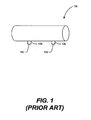
- FIGURE 1 illustrates a hydrajetting tool in accordance with the prior art.
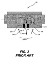
- FIGURE 2 illustrates the impact of damage causing factors on a hydrajetting tool in accordance with the prior art.
- FIGURE 3 illustrates the result of straight jetting and angled jetting using a hydrajetting tool in accordance with the prior art.
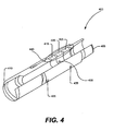
- FIGURE 4 illustrates a cutaway view of an improved jetting tool in accordance with an embodiment of the present invention depicting the solid sleeve, holders and associated parts.
- FIGURE 5 illustrates the impact of damage causing factors on an improved jetting tool in accordance with an embodiment of the present invention.
- the present invention primarily relates to mining and subterranean well formation. More particularly, the present invention relates to an improved method for perforating, slotting, and cutting steel and subterranean rock; and also for fracturing a subterranean formation to stimulate the production of desired fluids therefrom.
- the high pressure exerted on the formation at the tip of the cavity causes a fracture to be formed and extend some distance into the formation.
- a propping agent is suspended in the fracturing fluid which is deposited in the fracture.
- the propping agent may be a granular substance such as, for example, sand grains, ceramic or bauxite or other man-made grains, walnut shells, or other material carried in suspension by the fracturing fluid.
- the propping agent functions to prevent the fractures from closing and thereby provides conductive channels in the formation through which produced fluids can readily flow to the well bore.
- the presence of the propping agent also increases the erosive effect of the jetting fluid.
- a fracturing fluid is pumped through the fracturing tool and into the well bore to raise the ambient fluid pressure exerted on the formation.
- the fluid is pumped into the fracture at a rate and high pressure sufficient to extend the fracture an additional distance from the well bore into the formation.
- Nozzle 130 may extend beyond the surface of the outer wall as depicted in Figure 1 , or nozzle 130 may extend only to the surface of the outer wall of the hydrajetting tool 100.
- the orientation of nozzle 130 may be modified depending upon the formation to be fractured.
- the nozzle 130 has an exterior opening which acts as a nozzle opening 150 that allows the passage of fluids from the inner side of hydrajetting tool 100 through the nozzle 130.
- the nozzle 130 may be composed of any material that is capable of withstanding the stresses associated with fluid fracture, the abrasive nature of the fracturing or other treatment fluids and any proppants or other fracturing agents used.
- the materials that can be used for construction of the nozzle 130 may include, but are not limited to tungsten carbide, diamond composites, and certain ceramics.
- the nozzle 130 is often composed of abrasion resistive materials such as tungsten carbide, or other certain ceramics, such materials are expensive and brittle. As a result, a tool wholly made of such substances will likely shatter as it cannot withstand the forces encountered as it moves down to the site to be fractured. Consequently, the body of the hydrajetting tool 100 is typically made of steel or similar materials that although not brittle, are not strong enough to withstand the abrasive forces encountered during the hydrajetting process.
- FIG. 2 Shown in Figure 2 , is the impact of damage causing factors on a hydrajetting tool in accordance with the prior art. Arrows are used to show the direction of the fluid flow as the fluid approaches and exits the nozzle 130 through the nozzle opening 150. Typically, there are three distinct phenomena that damage the hydrajetting tool 100 as the fluid exits the nozzle 130.
- a slight movement of the hydrajetting tool 100 can initiate a Coriolis swirling effect.
- the hydrajetting tool 100 is not completely stationary during the jetting process. For example, the tool may move due to vibrations resulting from the jetting process. If the hydrajetting tool 100 turns during the jetting process it will cause the fluid to start swirling, thereby creating a tornado effect 240. As the fluid swirls 240 it further erodes the inner walls 245 of the hydrajetting tool 100 along its circumference.
- the third major source of damage to the hydrajetting tool 100 results from the reflection of the emitted fluid 250 from the perforations 255. As the fluid reflects 230 from the perforation it erodes 235 the hydrajetting tool 100. As discussed above, in some hydrajetting tools the direction of the nozzle opening 150 may be altered depending on the formation to be fractured. The damage resulting from the reflection of the fluid is shown in more detail in Figure 3 . Depicted in Figure 3 is a diagram showing the damage to the hydrajetting tool 100 due to reflected fluids from the perforations 255 with the nozzle 300, 315 at different angles.
- the reflection of the fluid onto the hydrajetting tool 100 is the least when the nozzle 300 shoots the fluid 305 straight into the perforation 255.
- the splashback fluid 310 which is moving in a direction opposite to that of the jet 305 reduces the effectiveness of the jet 305 leading to an ineffective cutting of the perforation 255.
- Jet 300 also reduces the effectiveness of the splashback fluid 310 in damaging the tool near the fluid exit of the jet. Massive erosion on the tool 235 still occur around the perimeter of the nozzle.
- applying the jet 320 at an angle makes the cutting process highly effective.
- due to angling the nozzle 315 the effect of fluid 325 reflected onto the hydrajetting tool 100 increases as the splashback fluid 325 is undeterred. Because the fluid 325 is shooting back at the hydrajetting tool 100 at full velocity, it will cut 330 the hydrajetting tool in a short amount of time.
- FIGURE 4 Shown in FIGURE 4 is a cutaway view of an improved jetting tool in accordance with an embodiment of the present invention shown generally with reference numeral 400.
- the improved jetting tool 400 includes a solid sleeve 440 comprising a plurality of hard material parts 415, 420 and 425.
- the hard material parts are made from a material having a hardness greater than 75 Rockwell A.
- the materials that may be used to make the hard material parts 415, 420, 425 include, but are not limited to, carbide or other ceramics with a high resistance to abrasive forces.
- the carbide used to make the hard material parts 415, 420 and 425 may be of all grades and may be a carbide with different types of binders or without binders.
- the binder may be made of a variety of suitable materials including, but not limited to, Molybdenum and Cobalt.
- Molybdenum and Cobalt the exemplary solid sleeve comprises three hard material parts 415, 420, 425, it would be readily apparent to one skilled in the art with the benefit of this disclosure that a different number of hard material parts can be used depending on the desired length of the jetting tool 400 and other factors such as the nature of the formation being fractured.
- the suitable hard materials such as carbide or other ceramics are brittle and easily shatter.
- This problem is resolved by enclosing the solid sleeve 440 between a first holder 405 on one side and a second holder 410 on the other side.
- the holders 405, 410 act as a carrier and sacrificial body on the outside of the solid sleeve 440.
- the primary purpose of the holders 405, 410 is to protect the solid sleeve 440 against shattering during the jetting process and as the tool is moved to and returned from a desired location.
- the holders may be made of a variety of materials including but not limited to steel, fiberglass, or other suitable materials.
- one of the hard material parts 420 includes a hole 430.
- holes 435 created on the body of the holders 405, 410 which are aligned to match the holes of the solid sleeve 440.
- the number of the holes and the angles at which the holes are located can be varied depending on the nature of the formation and other relevant factors in order to achieve a desirable performance. Because holes are created directly in the body of the jetting tool 400; a nozzle need not be used and the fluid can flow out of the jetting tool 400 through the holes in the walls.
- FIGURE 5 Shown in FIGURE 5 is the impact of damage causing factors on an improved jetting tool 400 in accordance with an embodiment of the present invention.
- the fluid 500 flows through the improved jetting tool 400 and exits through the hole 435 in the wall of the jetting tool 400.
- the causes of damage are the same as that discussed with regard to the Prior Art, namely, the fluid rapidly turning the corner 520, the fluid overshot 510, the Coriolis swirling of the fluid 540 and the reflection of the fluid 530 from the perforations 255.
- the solid sleeve 440 is composed of hard materials, it will not be eroded by the fluid turning the corner 520, the Coriolis swirling 540, or the overshot fluid 510. Moreover, although the reflection of the fluid 530 from the perforations 255 impacts the holder 405 and erodes 535 it, this erosion will not impact the performance of the jetting tool 400. Specifically, although the reflected fluid 530 may completely erode the holder 405, it cannot erode the hard material below it, and hence, cannot impact the operation of the jetting mechanism which is composed of the hard material forming the solid sleeve 440.
- the main purpose of the holder 405 is to prevent the shattering of the solid sleeve 440 and the holder 405 can perform that function despite having parts of its surface eroded 535 by the reflected fluid 530.
- the 'improved jetting tool 400 can withstand a long duration of jetting and need not be removed from the hole for part replacement until the job is completed.
- any damage to holders 405, 410 can easily be repaired by simply replacing them as they are made from cheap material and are easily separable from the solid sleeve 440.
- the improved jetting tool may be used in many other applications and industries.
Landscapes
- Life Sciences & Earth Sciences (AREA)
- Engineering & Computer Science (AREA)
- Geology (AREA)
- Mining & Mineral Resources (AREA)
- Physics & Mathematics (AREA)
- Environmental & Geological Engineering (AREA)
- Fluid Mechanics (AREA)
- General Life Sciences & Earth Sciences (AREA)
- Geochemistry & Mineralogy (AREA)
- Processing Of Stones Or Stones Resemblance Materials (AREA)
- Earth Drilling (AREA)
Claims (10)
- Verfahren zum Perforieren, Kerben und Schneiden von Stahl und unterirdischem Felsen oder Brechen einer unterirdischen Formation zum Stimulieren der Produktion von erwünschten Flüssigkeiten davon unter Verwendung eines Strahlwerkzeugs (400), umfassend eine Hülse (440), wobei
das Verfahren Flüssigkeit (500) umfasst, die durch die Hülse (440) fließt und aus der Hülse (440) durch mindestens eine Öffnung (430) in einer Wand der Hülse (440) austritt; und wobei:die Hülse (440) eine Vielzahl von Hartmaterialteilen mit einer Härte größer als 75 Rockwell A umfasst, dadurch gekennzeichnet, dass die Hülse (440) zwischen einem ersten Halter (405) und einem zweiten Halter (410) eingeschlossen ist;mindestens eine Öffnung (435) in mindestens einem der Halter (405, 410) vorhanden ist;und mindestens eine Öffnung (430) in einer Wand der Hülse (440) mit mindestens einer Öffnung (435) in mindestens einem der Halter (405, 410) ausgerichtet ist;das Verfahren weiter umfassend, einen beschädigten Halter (405, 410) von der Hülse (440) zu trennen und ihn zu ersetzen. - Verfahren nach Anspruch 1, wobei die Hülse (440) zylindrisch ist.
- Verfahren nach Anspruch 1, wobei das Hartmaterial eine Keramik umfasst.
- Verfahren nach Anspruch 3, wobei die Keramik ein Carbid umfasst.
- Verfahren nach Anspruch 4, wobei das Carbid ein Carbid ohne einen Binder umfasst.
- Verfahren nach Anspruch 4, wobei das Carbid ein Carbid mit einem Binder umfasst.
- Verfahren nach Anspruch 6, wobei der Binder eines von Cobalt oder Molybdän ist.
- Verfahren nach Anspruch 1, wobei das Strahlwerkzeug ein Wasserstrahlwerkzeug ist.
- Verfahren nach Anspruch 1, wobei das Material eine Härte größer als 80 Rockwell A aufweist.
- Verfahren nach Anspruch 1, wobei das Strahlwerkzeug (400) ein Brechwerkzeug ist.
Priority Applications (1)
| Application Number | Priority Date | Filing Date | Title |
|---|---|---|---|
| PL08750500T PL2147190T3 (pl) | 2007-05-14 | 2008-05-01 | Hydrauliczne narzędzie rozbijające typu hydrajet do stosowania w ultra wysoce erozyjnym środowisku |
Applications Claiming Priority (2)
| Application Number | Priority Date | Filing Date | Title |
|---|---|---|---|
| US11/748,087 US7841396B2 (en) | 2007-05-14 | 2007-05-14 | Hydrajet tool for ultra high erosive environment |
| PCT/GB2008/001527 WO2008139141A1 (en) | 2007-05-14 | 2008-05-01 | Hydrajet tool for ultra high erosive environment |
Publications (2)
| Publication Number | Publication Date |
|---|---|
| EP2147190A1 EP2147190A1 (de) | 2010-01-27 |
| EP2147190B1 true EP2147190B1 (de) | 2012-02-22 |
Family
ID=39701141
Family Applications (1)
| Application Number | Title | Priority Date | Filing Date |
|---|---|---|---|
| EP08750500A Not-in-force EP2147190B1 (de) | 2007-05-14 | 2008-05-01 | Wasserstrahlwerkzeug für hocherosive umgebung |
Country Status (12)
| Country | Link |
|---|---|
| US (1) | US7841396B2 (de) |
| EP (1) | EP2147190B1 (de) |
| CN (1) | CN101680290B (de) |
| AR (1) | AR066548A1 (de) |
| AT (1) | ATE546613T1 (de) |
| AU (1) | AU2008249846B2 (de) |
| BR (1) | BRPI0809410A2 (de) |
| CA (1) | CA2681607C (de) |
| MX (1) | MX2009011686A (de) |
| PL (1) | PL2147190T3 (de) |
| RU (1) | RU2422626C1 (de) |
| WO (1) | WO2008139141A1 (de) |
Families Citing this family (20)
| Publication number | Priority date | Publication date | Assignee | Title |
|---|---|---|---|---|
| US8066059B2 (en) | 2005-03-12 | 2011-11-29 | Thru Tubing Solutions, Inc. | Methods and devices for one trip plugging and perforating of oil and gas wells |
| US8371369B2 (en) * | 2007-12-04 | 2013-02-12 | Baker Hughes Incorporated | Crossover sub with erosion resistant inserts |
| US8439116B2 (en) | 2009-07-24 | 2013-05-14 | Halliburton Energy Services, Inc. | Method for inducing fracture complexity in hydraulically fractured horizontal well completions |
| US8960292B2 (en) | 2008-08-22 | 2015-02-24 | Halliburton Energy Services, Inc. | High rate stimulation method for deep, large bore completions |
| US9016376B2 (en) | 2012-08-06 | 2015-04-28 | Halliburton Energy Services, Inc. | Method and wellbore servicing apparatus for production completion of an oil and gas well |
| US9796918B2 (en) | 2013-01-30 | 2017-10-24 | Halliburton Energy Services, Inc. | Wellbore servicing fluids and methods of making and using same |
| US8631872B2 (en) | 2009-09-24 | 2014-01-21 | Halliburton Energy Services, Inc. | Complex fracturing using a straddle packer in a horizontal wellbore |
| US8887803B2 (en) | 2012-04-09 | 2014-11-18 | Halliburton Energy Services, Inc. | Multi-interval wellbore treatment method |
| US8720566B2 (en) * | 2010-05-10 | 2014-05-13 | Halliburton Energy Services, Inc. | Slot perforating tool |
| US8448700B2 (en) * | 2010-08-03 | 2013-05-28 | Thru Tubing Solutions, Inc. | Abrasive perforator with fluid bypass |
| US9227204B2 (en) | 2011-06-01 | 2016-01-05 | Halliburton Energy Services, Inc. | Hydrajetting nozzle and method |
| US20130048282A1 (en) | 2011-08-23 | 2013-02-28 | David M. Adams | Fracturing Process to Enhance Propping Agent Distribution to Maximize Connectivity Between the Formation and the Wellbore |
| US9097104B2 (en) | 2011-11-09 | 2015-08-04 | Weatherford Technology Holdings, Llc | Erosion resistant flow nozzle for downhole tool |
| US9228422B2 (en) | 2012-01-30 | 2016-01-05 | Thru Tubing Solutions, Inc. | Limited depth abrasive jet cutter |
| US9410376B2 (en) | 2012-08-23 | 2016-08-09 | Ramax, Llc | Drill with remotely controlled operating modes and system and method for providing the same |
| US10094172B2 (en) | 2012-08-23 | 2018-10-09 | Ramax, Llc | Drill with remotely controlled operating modes and system and method for providing the same |
| US9677383B2 (en) | 2013-02-28 | 2017-06-13 | Weatherford Technology Holdings, Llc | Erosion ports for shunt tubes |
| CN104727794A (zh) * | 2015-02-03 | 2015-06-24 | 北京众博达石油科技有限公司 | 一种耐冲蚀喷射器 |
| CN106761597A (zh) * | 2016-12-27 | 2017-05-31 | 中国石油天然气股份有限公司 | 一种单翼水力喷射器 |
| US10677024B2 (en) | 2017-03-01 | 2020-06-09 | Thru Tubing Solutions, Inc. | Abrasive perforator with fluid bypass |
Citations (1)
| Publication number | Priority date | Publication date | Assignee | Title |
|---|---|---|---|---|
| US5636691A (en) * | 1995-09-18 | 1997-06-10 | Halliburton Energy Services, Inc. | Abrasive slurry delivery apparatus and methods of using same |
Family Cites Families (25)
| Publication number | Priority date | Publication date | Assignee | Title |
|---|---|---|---|---|
| US3145776A (en) | 1962-07-30 | 1964-08-25 | Halliburton Co | Hydra-jet tool |
| US4050529A (en) | 1976-03-25 | 1977-09-27 | Kurban Magomedovich Tagirov | Apparatus for treating rock surrounding a wellbore |
| US4103748A (en) * | 1976-12-10 | 1978-08-01 | Arnold James F | Method for inhibiting the wear in a well casing |
| US4243727A (en) * | 1977-04-25 | 1981-01-06 | Hughes Tool Company | Surface smoothed tool joint hardfacing |
| US5181569A (en) * | 1992-03-23 | 1993-01-26 | Otis Engineering Corporation | Pressure operated valve |
| RU2038466C1 (ru) * | 1993-03-01 | 1995-06-27 | Николай Александрович Петров | Гидроперфоратор |
| RU2057909C1 (ru) * | 1993-06-08 | 1996-04-10 | Николай Александрович Петров | Способ вторичного вскрытия продуктивного пласта и устройство для его осуществления |
| NO302252B1 (no) * | 1995-10-16 | 1998-02-09 | Magne Hovden | Spyleinnretning for spyling oppover i ringrommet mellom borerör og borehullsvegg i olje/gass/injeksjons-brönner |
| RU2118445C1 (ru) * | 1996-12-15 | 1998-08-27 | Татарский научно-исследовательский институт и проектный институт нефти | Способ вторичного вскрытия продуктивного пласта |
| US5765642A (en) | 1996-12-23 | 1998-06-16 | Halliburton Energy Services, Inc. | Subterranean formation fracturing methods |
| US6286599B1 (en) | 2000-03-10 | 2001-09-11 | Halliburton Energy Services, Inc. | Method and apparatus for lateral casing window cutting using hydrajetting |
| US8181703B2 (en) | 2003-05-16 | 2012-05-22 | Halliburton Energy Services, Inc. | Method useful for controlling fluid loss in subterranean formations |
| US7017665B2 (en) | 2003-08-26 | 2006-03-28 | Halliburton Energy Services, Inc. | Strengthening near well bore subterranean formations |
| US7059406B2 (en) | 2003-08-26 | 2006-06-13 | Halliburton Energy Services, Inc. | Production-enhancing completion methods |
| US7445045B2 (en) | 2003-12-04 | 2008-11-04 | Halliburton Energy Services, Inc. | Method of optimizing production of gas from vertical wells in coal seams |
| US7104320B2 (en) | 2003-12-04 | 2006-09-12 | Halliburton Energy Services, Inc. | Method of optimizing production of gas from subterranean formations |
| US7225869B2 (en) | 2004-03-24 | 2007-06-05 | Halliburton Energy Services, Inc. | Methods of isolating hydrajet stimulated zones |
| US7159660B2 (en) | 2004-05-28 | 2007-01-09 | Halliburton Energy Services, Inc. | Hydrajet perforation and fracturing tool |
| US7373989B2 (en) * | 2004-06-23 | 2008-05-20 | Weatherford/Lamb, Inc. | Flow nozzle assembly |
| US7090153B2 (en) * | 2004-07-29 | 2006-08-15 | Halliburton Energy Services, Inc. | Flow conditioning system and method for fluid jetting tools |
| CN2742133Y (zh) * | 2004-11-19 | 2005-11-23 | 刘淑清 | 石油生产井水力割缝深穿透高压喷枪喷嘴 |
| US7571766B2 (en) | 2006-09-29 | 2009-08-11 | Halliburton Energy Services, Inc. | Methods of fracturing a subterranean formation using a jetting tool and a viscoelastic surfactant fluid to minimize formation damage |
| US7617871B2 (en) | 2007-01-29 | 2009-11-17 | Halliburton Energy Services, Inc. | Hydrajet bottomhole completion tool and process |
| US20090120633A1 (en) | 2007-11-13 | 2009-05-14 | Earl Webb | Method for Stimulating a Well Using Fluid Pressure Waves |
| US8096358B2 (en) | 2008-03-27 | 2012-01-17 | Halliburton Energy Services, Inc. | Method of perforating for effective sand plug placement in horizontal wells |
-
2007
- 2007-05-14 US US11/748,087 patent/US7841396B2/en active Active
-
2008
- 2008-05-01 AU AU2008249846A patent/AU2008249846B2/en not_active Ceased
- 2008-05-01 WO PCT/GB2008/001527 patent/WO2008139141A1/en not_active Ceased
- 2008-05-01 PL PL08750500T patent/PL2147190T3/pl unknown
- 2008-05-01 CN CN200880016243.7A patent/CN101680290B/zh not_active Expired - Fee Related
- 2008-05-01 MX MX2009011686A patent/MX2009011686A/es active IP Right Grant
- 2008-05-01 RU RU2009146059/03A patent/RU2422626C1/ru not_active IP Right Cessation
- 2008-05-01 AT AT08750500T patent/ATE546613T1/de active
- 2008-05-01 CA CA2681607A patent/CA2681607C/en not_active Expired - Fee Related
- 2008-05-01 BR BRPI0809410-1A patent/BRPI0809410A2/pt not_active IP Right Cessation
- 2008-05-01 EP EP08750500A patent/EP2147190B1/de not_active Not-in-force
- 2008-05-13 AR ARP080102019A patent/AR066548A1/es active IP Right Grant
Patent Citations (1)
| Publication number | Priority date | Publication date | Assignee | Title |
|---|---|---|---|---|
| US5636691A (en) * | 1995-09-18 | 1997-06-10 | Halliburton Energy Services, Inc. | Abrasive slurry delivery apparatus and methods of using same |
Also Published As
| Publication number | Publication date |
|---|---|
| US20080283299A1 (en) | 2008-11-20 |
| PL2147190T3 (pl) | 2012-07-31 |
| RU2422626C1 (ru) | 2011-06-27 |
| AU2008249846A1 (en) | 2008-11-20 |
| CA2681607C (en) | 2012-03-13 |
| CN101680290A (zh) | 2010-03-24 |
| BRPI0809410A2 (pt) | 2014-09-16 |
| US7841396B2 (en) | 2010-11-30 |
| WO2008139141A1 (en) | 2008-11-20 |
| ATE546613T1 (de) | 2012-03-15 |
| CN101680290B (zh) | 2014-11-26 |
| AR066548A1 (es) | 2009-08-26 |
| CA2681607A1 (en) | 2008-11-20 |
| AU2008249846B2 (en) | 2013-01-31 |
| MX2009011686A (es) | 2009-11-10 |
| EP2147190A1 (de) | 2010-01-27 |
Similar Documents
| Publication | Publication Date | Title |
|---|---|---|
| CA2681607C (en) | Hydrajet tool for ultra high erosive environment | |
| US10337310B2 (en) | Method for the enhancement and stimulation of oil and gas production in shales | |
| US5950742A (en) | Methods and related equipment for rotary drilling | |
| US7159660B2 (en) | Hydrajet perforation and fracturing tool | |
| AU2008211776B2 (en) | Hydrajet bottomhole completion tool and process | |
| US20050274522A1 (en) | Limited entry multiple fracture and frac-pack placement in liner completions using liner fracturing tool | |
| US8757262B2 (en) | Apparatus and method for abrasive jet perforating and cutting of tubular members | |
| US20100212903A1 (en) | Apparatus and method for abrasive jet perforating | |
| WO2006136768A1 (en) | Methods and apparatus for multiple fracturing of subterranean formations | |
| GB2406114A (en) | Improving reservoir communication by creating a local underbalance and using treatment fluid | |
| US9416610B2 (en) | Apparatus and method for abrasive jet perforating | |
| EP2714205A2 (de) | Wasserstrahldüse und verfahren | |
| AU2013376965B2 (en) | Downhole tool with erosion resistant layer and method of use | |
| WO2016043699A1 (en) | Jetting tool for boosting pressures at target wellbore locations | |
| US20150144341A1 (en) | System and Method for Forming Cavities | |
| Samuel et al. | Introducing A New Dissolvable Abrasive Perforating Material to Enhance Fracturing Efficiency | |
| US9822616B2 (en) | Pressure actuated flow control in an abrasive jet perforating tool | |
| CA2132458A1 (en) | Multi- port oilfield liner connector | |
| Van Gijtenbeek et al. | Unique hydrajet tool provides cost savings and improved performance in placing many perforations and proppant fractures in horizontal wellbores | |
| OAsuelimen et al. | Effect of Perforation Job on Formation Damage |
Legal Events
| Date | Code | Title | Description |
|---|---|---|---|
| PUAI | Public reference made under article 153(3) epc to a published international application that has entered the european phase |
Free format text: ORIGINAL CODE: 0009012 |
|
| 17P | Request for examination filed |
Effective date: 20091111 |
|
| AK | Designated contracting states |
Kind code of ref document: A1 Designated state(s): AT BE BG CH CY CZ DE DK EE ES FI FR GB GR HR HU IE IS IT LI LT LU LV MC MT NL NO PL PT RO SE SI SK TR |
|
| AX | Request for extension of the european patent |
Extension state: AL BA MK RS |
|
| 17Q | First examination report despatched |
Effective date: 20100325 |
|
| DAX | Request for extension of the european patent (deleted) | ||
| GRAP | Despatch of communication of intention to grant a patent |
Free format text: ORIGINAL CODE: EPIDOSNIGR1 |
|
| GRAS | Grant fee paid |
Free format text: ORIGINAL CODE: EPIDOSNIGR3 |
|
| GRAA | (expected) grant |
Free format text: ORIGINAL CODE: 0009210 |
|
| AK | Designated contracting states |
Kind code of ref document: B1 Designated state(s): AT BE BG CH CY CZ DE DK EE ES FI FR GB GR HR HU IE IS IT LI LT LU LV MC MT NL NO PL PT RO SE SI SK TR |
|
| REG | Reference to a national code |
Ref country code: GB Ref legal event code: FG4D |
|
| REG | Reference to a national code |
Ref country code: CH Ref legal event code: EP |
|
| REG | Reference to a national code |
Ref country code: AT Ref legal event code: REF Ref document number: 546613 Country of ref document: AT Kind code of ref document: T Effective date: 20120315 |
|
| REG | Reference to a national code |
Ref country code: IE Ref legal event code: FG4D |
|
| REG | Reference to a national code |
Ref country code: DE Ref legal event code: R096 Ref document number: 602008013605 Country of ref document: DE Effective date: 20120419 |
|
| REG | Reference to a national code |
Ref country code: NL Ref legal event code: VDEP Effective date: 20120222 |
|
| LTIE | Lt: invalidation of european patent or patent extension |
Effective date: 20120222 |
|
| PG25 | Lapsed in a contracting state [announced via postgrant information from national office to epo] |
Ref country code: NO Free format text: LAPSE BECAUSE OF FAILURE TO SUBMIT A TRANSLATION OF THE DESCRIPTION OR TO PAY THE FEE WITHIN THE PRESCRIBED TIME-LIMIT Effective date: 20120522 Ref country code: LT Free format text: LAPSE BECAUSE OF FAILURE TO SUBMIT A TRANSLATION OF THE DESCRIPTION OR TO PAY THE FEE WITHIN THE PRESCRIBED TIME-LIMIT Effective date: 20120222 Ref country code: IS Free format text: LAPSE BECAUSE OF FAILURE TO SUBMIT A TRANSLATION OF THE DESCRIPTION OR TO PAY THE FEE WITHIN THE PRESCRIBED TIME-LIMIT Effective date: 20120622 Ref country code: HR Free format text: LAPSE BECAUSE OF FAILURE TO SUBMIT A TRANSLATION OF THE DESCRIPTION OR TO PAY THE FEE WITHIN THE PRESCRIBED TIME-LIMIT Effective date: 20120222 Ref country code: NL Free format text: LAPSE BECAUSE OF FAILURE TO SUBMIT A TRANSLATION OF THE DESCRIPTION OR TO PAY THE FEE WITHIN THE PRESCRIBED TIME-LIMIT Effective date: 20120222 |
|
| REG | Reference to a national code |
Ref country code: PL Ref legal event code: T3 |
|
| PG25 | Lapsed in a contracting state [announced via postgrant information from national office to epo] |
Ref country code: BE Free format text: LAPSE BECAUSE OF FAILURE TO SUBMIT A TRANSLATION OF THE DESCRIPTION OR TO PAY THE FEE WITHIN THE PRESCRIBED TIME-LIMIT Effective date: 20120222 Ref country code: GR Free format text: LAPSE BECAUSE OF FAILURE TO SUBMIT A TRANSLATION OF THE DESCRIPTION OR TO PAY THE FEE WITHIN THE PRESCRIBED TIME-LIMIT Effective date: 20120523 Ref country code: FI Free format text: LAPSE BECAUSE OF FAILURE TO SUBMIT A TRANSLATION OF THE DESCRIPTION OR TO PAY THE FEE WITHIN THE PRESCRIBED TIME-LIMIT Effective date: 20120222 Ref country code: PT Free format text: LAPSE BECAUSE OF FAILURE TO SUBMIT A TRANSLATION OF THE DESCRIPTION OR TO PAY THE FEE WITHIN THE PRESCRIBED TIME-LIMIT Effective date: 20120622 Ref country code: LV Free format text: LAPSE BECAUSE OF FAILURE TO SUBMIT A TRANSLATION OF THE DESCRIPTION OR TO PAY THE FEE WITHIN THE PRESCRIBED TIME-LIMIT Effective date: 20120222 |
|
| REG | Reference to a national code |
Ref country code: AT Ref legal event code: MK05 Ref document number: 546613 Country of ref document: AT Kind code of ref document: T Effective date: 20120222 |
|
| PG25 | Lapsed in a contracting state [announced via postgrant information from national office to epo] |
Ref country code: CY Free format text: LAPSE BECAUSE OF FAILURE TO SUBMIT A TRANSLATION OF THE DESCRIPTION OR TO PAY THE FEE WITHIN THE PRESCRIBED TIME-LIMIT Effective date: 20120222 |
|
| PG25 | Lapsed in a contracting state [announced via postgrant information from national office to epo] |
Ref country code: DK Free format text: LAPSE BECAUSE OF FAILURE TO SUBMIT A TRANSLATION OF THE DESCRIPTION OR TO PAY THE FEE WITHIN THE PRESCRIBED TIME-LIMIT Effective date: 20120222 Ref country code: SE Free format text: LAPSE BECAUSE OF FAILURE TO SUBMIT A TRANSLATION OF THE DESCRIPTION OR TO PAY THE FEE WITHIN THE PRESCRIBED TIME-LIMIT Effective date: 20120222 Ref country code: SI Free format text: LAPSE BECAUSE OF FAILURE TO SUBMIT A TRANSLATION OF THE DESCRIPTION OR TO PAY THE FEE WITHIN THE PRESCRIBED TIME-LIMIT Effective date: 20120222 Ref country code: RO Free format text: LAPSE BECAUSE OF FAILURE TO SUBMIT A TRANSLATION OF THE DESCRIPTION OR TO PAY THE FEE WITHIN THE PRESCRIBED TIME-LIMIT Effective date: 20120222 Ref country code: CZ Free format text: LAPSE BECAUSE OF FAILURE TO SUBMIT A TRANSLATION OF THE DESCRIPTION OR TO PAY THE FEE WITHIN THE PRESCRIBED TIME-LIMIT Effective date: 20120222 Ref country code: EE Free format text: LAPSE BECAUSE OF FAILURE TO SUBMIT A TRANSLATION OF THE DESCRIPTION OR TO PAY THE FEE WITHIN THE PRESCRIBED TIME-LIMIT Effective date: 20120222 |
|
| PG25 | Lapsed in a contracting state [announced via postgrant information from national office to epo] |
Ref country code: SK Free format text: LAPSE BECAUSE OF FAILURE TO SUBMIT A TRANSLATION OF THE DESCRIPTION OR TO PAY THE FEE WITHIN THE PRESCRIBED TIME-LIMIT Effective date: 20120222 Ref country code: IT Free format text: LAPSE BECAUSE OF FAILURE TO SUBMIT A TRANSLATION OF THE DESCRIPTION OR TO PAY THE FEE WITHIN THE PRESCRIBED TIME-LIMIT Effective date: 20120222 |
|
| PLBE | No opposition filed within time limit |
Free format text: ORIGINAL CODE: 0009261 |
|
| STAA | Information on the status of an ep patent application or granted ep patent |
Free format text: STATUS: NO OPPOSITION FILED WITHIN TIME LIMIT |
|
| PG25 | Lapsed in a contracting state [announced via postgrant information from national office to epo] |
Ref country code: MC Free format text: LAPSE BECAUSE OF NON-PAYMENT OF DUE FEES Effective date: 20120531 |
|
| REG | Reference to a national code |
Ref country code: CH Ref legal event code: PL |
|
| 26N | No opposition filed |
Effective date: 20121123 |
|
| GBPC | Gb: european patent ceased through non-payment of renewal fee |
Effective date: 20120522 |
|
| PG25 | Lapsed in a contracting state [announced via postgrant information from national office to epo] |
Ref country code: LI Free format text: LAPSE BECAUSE OF NON-PAYMENT OF DUE FEES Effective date: 20120531 Ref country code: CH Free format text: LAPSE BECAUSE OF NON-PAYMENT OF DUE FEES Effective date: 20120531 Ref country code: AT Free format text: LAPSE BECAUSE OF FAILURE TO SUBMIT A TRANSLATION OF THE DESCRIPTION OR TO PAY THE FEE WITHIN THE PRESCRIBED TIME-LIMIT Effective date: 20120222 |
|
| REG | Reference to a national code |
Ref country code: IE Ref legal event code: MM4A |
|
| REG | Reference to a national code |
Ref country code: DE Ref legal event code: R097 Ref document number: 602008013605 Country of ref document: DE Effective date: 20121123 |
|
| PG25 | Lapsed in a contracting state [announced via postgrant information from national office to epo] |
Ref country code: ES Free format text: LAPSE BECAUSE OF FAILURE TO SUBMIT A TRANSLATION OF THE DESCRIPTION OR TO PAY THE FEE WITHIN THE PRESCRIBED TIME-LIMIT Effective date: 20120602 Ref country code: GB Free format text: LAPSE BECAUSE OF NON-PAYMENT OF DUE FEES Effective date: 20120522 Ref country code: IE Free format text: LAPSE BECAUSE OF NON-PAYMENT OF DUE FEES Effective date: 20120501 |
|
| REG | Reference to a national code |
Ref country code: DE Ref legal event code: R082 Ref document number: 602008013605 Country of ref document: DE Representative=s name: WEISSE, RENATE, DIPL.-PHYS. DR.-ING., DE |
|
| PG25 | Lapsed in a contracting state [announced via postgrant information from national office to epo] |
Ref country code: MT Free format text: LAPSE BECAUSE OF FAILURE TO SUBMIT A TRANSLATION OF THE DESCRIPTION OR TO PAY THE FEE WITHIN THE PRESCRIBED TIME-LIMIT Effective date: 20120222 Ref country code: BG Free format text: LAPSE BECAUSE OF FAILURE TO SUBMIT A TRANSLATION OF THE DESCRIPTION OR TO PAY THE FEE WITHIN THE PRESCRIBED TIME-LIMIT Effective date: 20120522 |
|
| PG25 | Lapsed in a contracting state [announced via postgrant information from national office to epo] |
Ref country code: TR Free format text: LAPSE BECAUSE OF FAILURE TO SUBMIT A TRANSLATION OF THE DESCRIPTION OR TO PAY THE FEE WITHIN THE PRESCRIBED TIME-LIMIT Effective date: 20120222 |
|
| PG25 | Lapsed in a contracting state [announced via postgrant information from national office to epo] |
Ref country code: LU Free format text: LAPSE BECAUSE OF NON-PAYMENT OF DUE FEES Effective date: 20120501 |
|
| PG25 | Lapsed in a contracting state [announced via postgrant information from national office to epo] |
Ref country code: HU Free format text: LAPSE BECAUSE OF FAILURE TO SUBMIT A TRANSLATION OF THE DESCRIPTION OR TO PAY THE FEE WITHIN THE PRESCRIBED TIME-LIMIT Effective date: 20080501 |
|
| REG | Reference to a national code |
Ref country code: FR Ref legal event code: PLFP Year of fee payment: 8 |
|
| REG | Reference to a national code |
Ref country code: FR Ref legal event code: PLFP Year of fee payment: 9 |
|
| PGFP | Annual fee paid to national office [announced via postgrant information from national office to epo] |
Ref country code: PL Payment date: 20160321 Year of fee payment: 9 |
|
| PGFP | Annual fee paid to national office [announced via postgrant information from national office to epo] |
Ref country code: DE Payment date: 20160329 Year of fee payment: 9 |
|
| PGFP | Annual fee paid to national office [announced via postgrant information from national office to epo] |
Ref country code: FR Payment date: 20160322 Year of fee payment: 9 |
|
| REG | Reference to a national code |
Ref country code: DE Ref legal event code: R119 Ref document number: 602008013605 Country of ref document: DE |
|
| REG | Reference to a national code |
Ref country code: FR Ref legal event code: ST Effective date: 20180131 |
|
| PG25 | Lapsed in a contracting state [announced via postgrant information from national office to epo] |
Ref country code: DE Free format text: LAPSE BECAUSE OF NON-PAYMENT OF DUE FEES Effective date: 20171201 |
|
| PG25 | Lapsed in a contracting state [announced via postgrant information from national office to epo] |
Ref country code: FR Free format text: LAPSE BECAUSE OF NON-PAYMENT OF DUE FEES Effective date: 20170531 |
|
| PG25 | Lapsed in a contracting state [announced via postgrant information from national office to epo] |
Ref country code: PL Free format text: LAPSE BECAUSE OF NON-PAYMENT OF DUE FEES Effective date: 20170501 |