EP2147233B2 - Carter pour boîte de vitesses, boîte de vitesses, procede et gamme de boîtes de vitesses - Google Patents
Carter pour boîte de vitesses, boîte de vitesses, procede et gamme de boîtes de vitesses Download PDFInfo
- Publication number
- EP2147233B2 EP2147233B2 EP08734969.2A EP08734969A EP2147233B2 EP 2147233 B2 EP2147233 B2 EP 2147233B2 EP 08734969 A EP08734969 A EP 08734969A EP 2147233 B2 EP2147233 B2 EP 2147233B2
- Authority
- EP
- European Patent Office
- Prior art keywords
- housing
- shell
- gearbox
- variant
- housing shell
- Prior art date
- Legal status (The legal status is an assumption and is not a legal conclusion. Google has not performed a legal analysis and makes no representation as to the accuracy of the status listed.)
- Active
Links
Images


Classifications
-
- F—MECHANICAL ENGINEERING; LIGHTING; HEATING; WEAPONS; BLASTING
- F16—ENGINEERING ELEMENTS AND UNITS; GENERAL MEASURES FOR PRODUCING AND MAINTAINING EFFECTIVE FUNCTIONING OF MACHINES OR INSTALLATIONS; THERMAL INSULATION IN GENERAL
- F16H—GEARING
- F16H57/00—General details of gearing
- F16H57/02—Gearboxes; Mounting gearing therein
- F16H57/033—Series gearboxes, e.g. gearboxes based on the same design being available in different sizes or gearboxes using a combination of several standardised units
Definitions
- the invention relates to a housing for a transmission and a transmission series.
- a transmission housing for a vehicle transmission is known, which is composed of two identical housing shells.
- a further variant, which combines one of the housing forces with a weight-reduced housing half, is not formed with any of the known housing halves
- the invention has the object of developing a gearbox series while reducing manufacturing costs.
- the object is achieved in the housing for a transmission according to the features defined in claim 1 and in the transmission series according to the features specified in claim 8.
- the EP-A-1 610 031 A2 discloses a housing with the pre-characterizing features of claim 1.
- the lower housing shell has foot flanges and mounting holes for mounting the transmission on a base.
- the transmission housing is safe and stable mountable on a base.
- a bevel gear stage wherein portions of the bearing bore for the bevel gear shaft are provided in both housing shells.
- an oil catcher pocket in the lower housing shell. provided, in particular integrally formed with her.
- oil collecting pockets are provided in the housing shells such that the respective collecting openings point away from one another.
- the lower housing shell has a cuboid outer shape and the upper housing shell an outer shape, which results from the lower housing shell by cutting away edges.
- Lageraufdickept are provided for reinforcing the shaft bearing bores.
- the advantage here is that the wall thickness of the housing shells can be reduced while maintaining the same capacity. Thus, the use of materials can be reduced.
- the Lageraufdickitch in the gearbox interior is provided.
- the upper housing shell on the inside of reinforcing ribs which extend away from the Lageraufdickitch.
- lateral forces can be derived from the shaft bearings in the shaft bores of the bearing thickenings, and the required wall thickness for the housing shells can be reduced.
- upper and lower housing shells have identical centering means, the centering being provided by intermediate parts and / or further centering means.
- the upper and lower housing shell are identically formed and there are simultaneously providable centering, which avoid deformation of the housing shells in particular by internal material stresses after the introduction of the shaft holes or make ineffective.
- pin holes are provided in the contact surface in the upper housing shell and in the lower housing shell and connected to the lower housing shell by centering pins that sit over a press fit in the pin bores.
- the upper housing shell is connected to the lower housing shell by threaded bolts, each threaded bolt is guided through a bore in the lower housing shell and is screwed into a blind hole of the upper housing shell.
- the housing shells are tight and detachable connectable, and it is an ingress of liquids in the holes of the threaded bolt and thus unwanted corrosion avoidable.
- the upper housing shell on a terminal block for an oil cooler and / or an oil filter and / or a fan cover can advantageously be provided.
- An inventive housing is advantageously used in a transmission with at least one gear stage, in which it receives the at least one gear stage, that surrounds the housing forming.
- the housing is composed of two housing shells, which are made of identical castings, in particular by Bohrbebeitbeitung, and in a second variant, the housing is composed of a housing lower shell as the lower housing shell and a housing upper shell as the upper housing shell, wherein the housing lower shell is made of a cast part of the housing shell of the first variant identical casting and the housing upper shell is made of a casting, which has a relation to the casting of the first variant reduced mass.
- the mass reduction is effected by a thinner wall thickness of the housing upper shell relative to the wall thickness of the housing lower shell and / or by a reduced outer surface of the upper housing shell relative to the outer surface of the lower housing shell.
- blind holes are made for connecting bolts in each variant in the upper housing shell and there are provided in the lower housing shell through holes for carrying out the connecting bolt.
- the housing is composed of two housing shells in a third variant, which are made of identical castings, in particular by drilling, the castings are identical to the casting of the housing upper shell of the second variant.
- the drilling process involves the introduction of guide and receiving holes for connecting bolts and connecting bolts, which hold and fix the housing parts together.
- the drilling can also involve the introduction, so for example, milling, maintenance openings, which are to install depending on the installation position and customer request.
- a particularly lightweight, so cost-effective because of low material usage, and space-saving variant is provided, which is particularly useful when the attachment of the transmission to a frame or on a base does not have to absorb excessive forces.
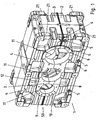
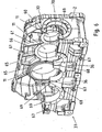
- FIG. 1 an inventive two-shell gear housing 1 is shown.
- the gear housing 1 is composed of a lower housing shell 2 and an upper housing shell 3, wherein the housing shells touch on contact surfaces 50.
- the terms above and below refer to the orientation of the transmission in the gravitational field of the earth and fall in the transmission housing 1 of FIG. 1 with the orientation of FIG. 1 together.
- bearing bores 11 are introduced, wherein a portion of each bearing bore 11 is provided in the upper housing shell 3, and another portion of the same bearing bore is provided in each case in the lower housing shell 2.
- the housing shells 2 and 3 are made of identical castings, ie castings or prototypes, by machining processes such as drilling, cutting, milling.
- Each housing shell 2, 3 has a cuboid outer contour, so that the transmission housing 1 has a total of a cuboid shape.
- the housing shells 2, 3 have sealing surfaces 12, on the bearing cap can be placed to complete the shaft bearing in the bearing bores 11. In the sealing surfaces 12 blind holes 6 are introduced to secure the bearing cap.
- the lower housing shell 2 and the upper housing shell 3 are made of identical castings. In particular, both housing shells match in their outer shape and differ by subsequently introduced holes.
- the upper housing shell 3 has borehole surfaces 4, in which no oil drain holes were introduced, since due to the use as an upper housing shell oil drain holes are superfluous.
- oil passages 8 and a pressure port 10 are introduced for the connection of a Wellenendpumpe.
- suction port 9 In the upper housing shell 3 oil passages 7 and a suction port 9 are introduced for the connection of a Wellenendpumpe.
- the suction port 9 has a larger diameter than the pressure port 10.
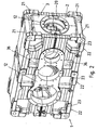
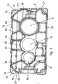
- FIG. 2 shows the rear view of the gear housing 1.
- Kegelradwellenbohrung 20 is provided for receiving the shaft bearing of a bevel gear.
- the side surface has on both housing shells flange surfaces 21 for mounting the fan cowl of a geared fan, which is mounted on the driving shaft of the bevel gear.
- Flange surfaces 21 are additionally provided on the side facing away from the bevel gear stage for mounting the gear housing 1 in an upright position, ie in a design with upwardly pointing bevel gear. Likewise, the flange surfaces 21 of the bevel gear side for mounting the gear housing 1 in a design with pointing down bevel gear shaft .verwendbar.
- foot flanges 22 are formed for fastening the gear housing 1 on a base.
- the gear housing 1 is fastened by means of fastening holes 23 plugged screws on the pad.
- the upper housing shell 3 has just such foot flanges 22 and mounting holes 23, so that on the one hand, the gear housing 1 in reverse design, ie orientation with respect to the gravitational field of the earth can be mounted and on the other hand, further devices can be mounted on the transmission housing.
- the bevel gear stage is eliminated, and the bevel gear shaft bore 20 is closed with a cover plate.
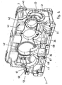
- FIG. 3 shows a further embodiment of a transmission housing 37 according to the invention.
- the transmission housing 37 comprises the lower housing shell 2 FIG. 1 and an upper housing shell 30.
- the upper housing shell 30 is roof-shaped withdrawn and therefore has an outer contour, which results from the outer contour of the lower housing shell 2, when the outer edges are cut off obliquely.
- a housing shell is provided which has a lower mass than the upper housing shell 3 FIG. 1 , An upside-down mounting of the gear housing is therefore not possible.
- inspection openings 33 are provided which can be closed with a lid.
- the upper housing shell 3 off FIG. 1 has no such inspection opening, because this would otherwise be provided in the lower housing shell 2 in order to use identical cast body can.
- an inspection opening in the lower housing shell would cause significant sealing problems.
- the housing upper shell 30 has on one side a bevel gear shaft bore 20 for mounting a bevel gear stage. On this side, flange surfaces 31 are provided, to which a fan cowl of a geared fan can be mounted. The flange surfaces 31 are, as in FIG. 7 seen, with respect to the flange 21 withdrawn. As a result, the mass of the housing upper shell 30 is further reduced with respect to the upper housing shell 3 FIG. 1 , An assembly of the gear housing 37 with downwardly pointing bevel gear is not possible without spacers.
- the housing upper shell 30 has on the side opposite the bevel gear side flange surfaces 21 for mounting the gear housing in a design with upwardly pointing bevel gear.
- the housing upper shell 30 further has a terminal block 32 with mounting surfaces 34, 35 for mounting an oil cooler or an oil filter or another accessory.
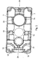
- FIG. 4 shows the gear housing 1 with cut upper housing shell 3.
- the interface 50 via which the upper housing shell 3 is connected to the lower housing shell 2 is defined at least on the following features: contact surfaces 41 in the lower housing shell 2 and upper housing shell 3, pin holes 47 and Bolt holes 68.
- the contact surfaces 41 allow a tight finish of the gearbox interior.
- the pin holes 47 are provided for centering pins, which are introduced via a press fit into the pin holes 47.
- the centering pins thus represent centering means which prevent deformation of the gear shells 2, 3 after introduction of the bearing bores 11.
- the bolt holes 68 serve to receive threaded bolts for fixed, detachable connection of the housing shells.
- the bolt holes 68 open into pockets 36, through which the threaded bolts can be inserted.
- bolt holes are introduced as blind holes at appropriate locations that do not open into pockets but are closed. Thus, liquids flowing from above are kept away from the bolt holes 68.
- the boundaries of the bearing bores 11 are reinforced in all housing shells by Lageraufdickitch 42. This Lageraufdickitch 42 point inward and are therefore beyond the inner wall of the housing shells 2, 3 also inside, except for areas in which pocket rear walls compensate for this protrusion.
- the upper housing shell 3 has on the bevel gear shaft bore 20 an oil collecting pocket 40 which has a groove-shaped upwards and is collected via the oil from the interior and passed into a hole provided at the lowest point of the oil collecting pocket 40 bore. This hole supplies oil to the bevel gear stage bearing. Since upper housing shell 3 and lower housing shell 2 are made of identical castings, the lower housing shell 2 has a similar oil collecting pocket, which faces away from the oil collecting pocket 40 and downwards. This oil catcher is due to the design of the transmission case 1 without function.
- FIG. 5 shows a section through the transmission housing 1 along a vertical plane passing through the Kegelradwellenbohrung 20.
- the upper housing shell 3 further has a bore for a suction port 52, while the lower housing shell 2 has a bore for a pressure port 51. Both ports 51, 52 serve to connect an optional shaft end pump and have functionally different diameters.
- the oil catching pocket 40 can be seen as well as the functionless oil collecting pocket 55, the collection opening of the collection opening of the oil collecting bag 40 away and facing down.
- the oil collecting pocket 55 is not possible to collect oil in the illustrated construction.
- the oil collecting pocket 55 is merely formed because the castings of the two housing shells are identical.
- FIG. 6 shows the transmission housing 37 from FIG. 3 with cut housing upper shell 30.
- the interface 70 via which the housing upper shell 30 is connected to the lower housing shell 2, is defined at least on the following features: Berzier vom 69 in the lower housing shell 2 and upper housing shell 30, pin bores 67 and bolt holes 68th
- the contact surfaces 69 effect a tight seal of the gearbox interior.
- the pin bores 67 are provided for centering pins, which are introduced via a press fit into the pin bores 67.
- the centering pins thus represent centering means which prevent deformation of the gear shells 2, 30 after introduction of the bearing bores 11.
- the bolt holes 68 serve to receive threaded bolts for fixed, detachable connection of the housing shells.
- the bolt holes 68 open into pockets 36, through which the threaded bolts can be inserted.
- bolt holes are introduced as blind holes at appropriate locations that do not open into pockets but are closed. Thus, liquids flowing from above are kept away from the bolt holes 68.
- the boundaries of the bearing bores 11 are reinforced in all housing shells by Lageraufdickitch 65. This Lageraufdickitch 65 point inwards and are therefore beyond the inner wall of the housing upper shell 30 into the interior. Starting from the bearing enlargements 65, reinforcing ribs 61 for reinforcing the housing wall extend on the inner wall of the housing upper shell 30.
- the housing upper shell 30 has on the bevel gear shaft bore 20 an oil collecting pocket 60, which has a channel-shaped upward and is collected via the oil from the interior and passed into a hole provided at the lowest point of the oil catching pocket 60 bore. This hole supplies oil to the bevel gear stage bearing.
- the lower housing shell 2 has a similar oil catching pocket, which points away from the oil collecting pocket 60 and down. This oil catcher pocket is due to the design of the gear housing 37 without function.
- FIG. 7 shows a section through the gear housing 37 along a vertical plane which passes through the bevel gear shaft bore 20.
- Reinforcing ribs 61 are provided on the transmission top shell 30, which start at the bearing thickening 65 of the central bearing bore and extend vertically upwards.
- reinforcing ribs 62, 63 and 64 are provided, which extend from the respective bearing bore 11 in the radial direction upwards.
- the outer contour of the housing upper shell 30 is in the region 71, ie in the region of the ears 72 for lifting the housing upper shell 30, roof-shaped retracted for mass reduction. In these withdrawn areas 71 kinks 73 are provided, so that overall results in the shape of a mansard roof for the outer contour of the housing upper shell.
- FIG. 8 shows the side view of the bevel gear side of the transmission housing 37 FIG. 3 ,
- the roof-shaped configuration of the outer contour of the housing upper shell 30 can be seen, which arises by cutting away edges 80 relative to the cuboid outer contour of the lower housing shell 2.
- kinks 81 in height of the terminal block 32 results in the shape of a mansard roof with two areas of different inclination.
- the shape of a top-flattened mansard hipped roof results with slopes on all four sides, each with two areas of different inclination.
- the housing of a transmission is formed by two housing upper shells, each identical to that in the Figures 3 and 6 to 8 shown housing upper shell 30 are formed, with their connecting flanges 41 are placed on each other.
- the reinforcing ribs 61 in the interior provide sufficient stability of the housing for many applications.
- the bolt holes 68 in FIG. 6 corresponding bolt holes are made at least on one of the two housing upper shells to the outside to allow insertion of connecting bolts or connecting bolts from the outside in assembled housing upper shells.
- the inspection openings 33 are introduced into one or both housing upper shells or not.
- the transmission housing thus produced has a particularly low mass and is suitable for installation in confined space conditions. A secure mounting and attachment is possible despite the lack of support footprint through the ears 72.
- housing is thus composed of housing shells, in one variant the housing shells are made of an identical cast body, in a second, weight-reduced variant, the housing shells are made of different castings and in a third, again reduced weight variant, the housing shells of identical castings are made, which resemble the weight-reduced castings of the second variant.
Landscapes
- Engineering & Computer Science (AREA)
- General Engineering & Computer Science (AREA)
- Mechanical Engineering (AREA)
- General Details Of Gearings (AREA)
Claims (11)
- Carter (1) pour boîte de vitesses,
ledit carter (1) étant composé d'une coque inférieure (2, 3) matérialisant une coque inférieure d'enveloppement, et d'une coque supérieure (30) matérialisant une coque supérieure d'enveloppement,
ladite coque inférieure (2, 3) du carter présentant des brides d'embase et des perçages de fixation, en vue du montage de la boîte de vitesses sur une structure sous-jacente,
et étant pourvu d'une zone d'interface (50, 70) dévolue à la liaison desdites coques (2, 3, 30) du carter,
sachant que les caractéristiques dont ladite zone d'interface (50, 70) est dotée, sur la coque inférieure (2, 3) du carter, se présentant en particulier comme des perçages, des surfaces de contact et des auxiliaires de centrage, sont de configuration identique à celle des caractéristiques dont ladite zone d'interface est dotée sur la coque supérieure (30) dudit carter,
de sorte qu'au lieu d'être reliée à la coque supérieure (30) du carter, la coque inférieure (2, 3) dudit carter peut aussi, sélectivement, être reliée à un modèle reproduit de ladite coque inférieure (2, 3) du carter, par l'intermédiaire de ladite zone d'interface (50, 70), afin de constituer une variante de carter,
caractérisé par le fait que
la coque supérieure (30) du carter se présente comme une pièce coulée offrant une masse réduite par rapport à la pièce coulée constituant la coque inférieure (2, 3) dudit carter,
la réduction de masse découlant du fait que ladite coque supérieure (30) du carter présente une épaisseur de paroi moindre que l'épaisseur de paroi de ladite coque inférieure (2, 3) dudit carter. - Carter (1) selon la revendication précédente,
caractérisé par
la présence d'un engrenage conique,
des régions partielles de l'alésage de portée (20), dévolu à l'arbre dudit engrenage conique, étant prévues dans les deux coques (2, 3) du carter,
et/ou une poche (40, 60) de recueil d'huile étant prévue dans la coque inférieure (2, 3) dudit carter, avec laquelle elle est notamment ménagée d'un seul tenant,
et/ou des poches (40, 60) de recueil d'huile étant prévues, dans les coques (2, 3, 30) dudit carter, de façon telle que les orifices collecteurs respectifs pointent mutuellement à l'opposé. - Carter (1) selon l'une des revendications précédentes,
caractérisé par le fait que
la coque inférieure (2, 3) du carter présente une forme extérieure parallélépipédique,
et la coque supérieure (30) dudit carter offre une forme extérieure obtenue à partir de ladite coque inférieure (2, 3) du carter, par rognage d'arêtes (71). - Carter (1) selon l'une des revendications précédentes,
caractérisé par le fait que
des renflements de montage (42, 65) sont prévus pour renforcer les alésages de portée d'arbres,
et/ou
lesdits renflements de montage (42, 65) pointent vers l'espace interne de la boîte de vitesses,
et/ou la coque supérieure (30) du carter comporte, sur la face intérieure, des nervures de renforcement (61, 62, 63, 64) qui s'étendent à partir desdits renflements de montage (42, 65). - Carter (1) selon l'une des revendications précédentes,
caractérisé par le fait que
les coques inférieure et supérieure (2, 3, 30) dudit carter sont équipées de moyens de centrage (67) identiques, le centrage étant instauré par des pièces intercalaires et/ou par des moyens supplémentaires de centrage. - Carter (1) selon l'une des revendications précédentes,
caractérisé par le fait que
des perçages d'emboîtement (67) sont prévus, dans la surface de contact, dans la coque supérieure (30) du carter et dans la coque inférieure (2, 3) dudit carter,
et que des tenons de centrage, reliés à ladite coque inférieure (2, 3) du carter, sont logés dans lesdits perçages d'emboîtement (67) par ajustement serré,
et/ou
la coque supérieure (30) du carter est reliée à la coque inférieure (2, 3) dudit carter par l'intermédiaire d'axes filetés, chaque axe fileté étant guidé par un alésage (68) pratiqué dans ladite coque inférieure (2, 3) dudit carter, et étant vissé dans un trou borgne (6) de ladite coque supérieure (30) dudit carter,
et/ou
ladite coque supérieure (30) du carter présente une barrette de rattachement destinée à un refroidisseur d'huile et/ou à un filtre à huile et/ou à un manchon de ventilateur. - Boîte de vitesses munie d'un carter (1) renfermant au moins un étage de ladite boîte,
caractérisée par le fait que
ledit carter (1) est réalisé conformément à l'une des revendications précédentes. - Gamme de boîtes de vitesses
incluant des variantes respectivement pourvues d'un carter (1), sachant que,
dans une première variante, ledit carter (1) est composé de deux coques (2, 3) produites à partir de pièces coulées identiques, notamment par des opérations d'alésage, et, dans une deuxième variante, ledit carter (1) est composé d'une coque inférieure (2, 3) matérialisant une coque inférieure d'enveloppement, et d'une coque supérieure (30) matérialisant une coque supérieure d'enveloppement,
ladite coque inférieure (2, 3) du carter étant produite à partir d'une pièce coulée identique à la pièce coulée de la coque (2, 3) du carter selon la première variante,
et ladite coque supérieure (30) du carter étant produite à partir d'une pièce coulée offrant une masse réduite par rapport à la pièce coulée de la première variante,
la réduction de masse découlant du fait que ladite coque supérieure (30) du carter présente une épaisseur de paroi (75) moindre que l'épaisseur de paroi (74) de ladite coque inférieure (2, 3) dudit carter. - Gamme de boîtes de vitesses, selon la revendication 8,
caractérisée par le fait que
la réduction de masse découle du fait que la coque supérieure (30) du carter présente une surface extérieure diminuée par rapport à la surface extérieure de la coque inférieure (2, 3) dudit carter,
sachant notamment que, dans chaque variante, des trous borgnes (6) dédiés à des axes filetés de liaison sont pratiqués dans ladite coque supérieure (30) du carter et que des perçages traversants (68), dévolus au passage desdits axes filetés de liaison, sont prévus dans ladite coque inférieure (2, 3) dudit carter. - Gamme de boîtes de vitesses, selon l'une des revendications 8 ou 9,
caractérisée par le fait que,
dans une troisième variante, le carter (1) est composé de deux coques produites à partir de pièces coulées identiques, notamment par des opérations d'alésage,
lesdites pièces coulées étant identiques à la pièce coulée de la coque supérieure du carter selon la deuxième variante. - Gamme de boîtes de vitesses, selon l'une des revendications 8 à 10,
caractérisée par le fait que
la coque supérieure (30) de carter et la coque inférieure (2, 3) de carter forment un carter (1) selon l'une des revendications 1-8 précédentes, et/ou forment un carter (1) produit selon l'une des revendications 10 ou 11 qui précèdent.
Applications Claiming Priority (3)
| Application Number | Priority Date | Filing Date | Title |
|---|---|---|---|
| DE102007017883 | 2007-04-13 | ||
| DE102008004337.0A DE102008004337B4 (de) | 2007-04-13 | 2008-01-15 | Gehäuse für ein Getriebe, Getriebe und Getriebe-Baureihe |
| PCT/EP2008/002626 WO2008125219A1 (fr) | 2007-04-13 | 2008-04-02 | Carter pour boîte de vitesses, boîte de vitesses, procédé et gamme de boîtes de vitesses |
Publications (3)
| Publication Number | Publication Date |
|---|---|
| EP2147233A1 EP2147233A1 (fr) | 2010-01-27 |
| EP2147233B1 EP2147233B1 (fr) | 2011-09-14 |
| EP2147233B2 true EP2147233B2 (fr) | 2015-07-29 |
Family
ID=39744375
Family Applications (1)
| Application Number | Title | Priority Date | Filing Date |
|---|---|---|---|
| EP08734969.2A Active EP2147233B2 (fr) | 2007-04-13 | 2008-04-02 | Carter pour boîte de vitesses, boîte de vitesses, procede et gamme de boîtes de vitesses |
Country Status (4)
| Country | Link |
|---|---|
| EP (1) | EP2147233B2 (fr) |
| AT (1) | ATE524672T1 (fr) |
| DE (1) | DE102008004337B4 (fr) |
| WO (1) | WO2008125219A1 (fr) |
Families Citing this family (21)
| Publication number | Priority date | Publication date | Assignee | Title |
|---|---|---|---|---|
| GB2469267A (en) * | 2009-04-03 | 2010-10-13 | Gm Global Tech Operations Inc | A gear case for supporting a gear assembly for an automobile and method of assembling such a gear case |
| CN102990286B (zh) * | 2011-09-16 | 2015-04-08 | 鞠小平 | 一种制动器用主减速器壳总成的加工方法 |
| DE102012008653B4 (de) * | 2012-05-03 | 2021-09-16 | Sew-Eurodrive Gmbh & Co Kg | Getriebe mit Getriebegehäuseteil mit an seiner Oberfläche angeordneten Gehäusetaschen oder Vertiefungen |
| CN103331634B (zh) * | 2013-05-29 | 2016-03-16 | 孙效 | 砻谷机齿轮箱镗孔方法 |
| DE102013018713B4 (de) * | 2013-11-08 | 2025-10-02 | Sew-Eurodrive Gmbh & Co Kg | Getriebe mit Gehäuse |
| DE102013018712B4 (de) | 2013-11-08 | 2024-09-12 | Sew-Eurodrive Gmbh & Co Kg | Getriebe mit Gehäuse |
| DE102013018709A1 (de) * | 2013-11-08 | 2015-05-13 | Sew-Eurodrive Gmbh & Co Kg | Gehäuse für ein Getriebe |
| DE102013018708A1 (de) | 2013-11-08 | 2015-05-13 | Sew-Eurodrive Gmbh & Co Kg | Gehäuse für ein Getriebe und Getriebe mit einem Gehäuse |
| CN104712739B (zh) * | 2013-12-17 | 2017-11-24 | Sew-工业减速机(天津)有限公司 | 用于减速器的壳体和具有壳体的减速器 |
| CN104712744B (zh) * | 2013-12-17 | 2018-01-19 | Sew-工业减速机(天津)有限公司 | 用于减速器的壳体 |
| CN103753227B (zh) * | 2014-01-21 | 2016-08-17 | 重庆大江工业有限责任公司 | 桥壳体构件的加工生产线及加工方法 |
| GB2523765B (en) * | 2014-03-04 | 2016-09-28 | Johnston Sweepers Ltd | Powertrain for a road cleaning vehicle |
| CN105443729A (zh) * | 2014-08-14 | 2016-03-30 | 陈俊 | 具有工具箱的减速器箱 |
| CN105333106A (zh) * | 2014-08-14 | 2016-02-17 | 陈俊 | 具有观察窗的减速器箱 |
| JP6599257B2 (ja) * | 2016-01-29 | 2019-10-30 | 住友重機械工業株式会社 | ケーシング |
| FI3649377T3 (fi) | 2017-07-06 | 2023-05-05 | Sew Eurodrive Gmbh & Co Kg | Vaihteisto sekä menetelmä kotelolla varustetun vaihteiston valmistamiseksi |
| DE102021003132A1 (de) | 2020-07-21 | 2022-01-27 | Sew-Eurodrive Gmbh & Co Kg | Getriebemotor, aufweisend ein Getriebe, einen Elektromotor und einen Adapterflansch |
| CN112676603B (zh) * | 2020-11-16 | 2023-08-18 | 中国航发西安动力控制科技有限公司 | T型壳体组件组合加工方法 |
| US20250297676A1 (en) | 2022-04-28 | 2025-09-25 | Sew-Eurodrive Gmbh & Co. Kg | Transmission with housing parts, for example, two identically configured housing parts |
| CN117006231A (zh) | 2022-04-28 | 2023-11-07 | Sew-工业减速机(天津)有限公司 | 具有两个彼此构造相同的壳体部件的减速器 |
| DE102023002524A1 (de) | 2022-07-12 | 2024-01-18 | Sew-Eurodrive Gmbh & Co Kg | Getriebe mit Gehäuse |
Citations (1)
| Publication number | Priority date | Publication date | Assignee | Title |
|---|---|---|---|---|
| DE4227512C1 (de) † | 1992-08-20 | 1994-03-31 | Dorstener Maschf Ag | Getriebeaggregat für den Antrieb von Mühlen, insbesondere Mühlen mit vertikaler Drehachse |
Family Cites Families (8)
| Publication number | Priority date | Publication date | Assignee | Title |
|---|---|---|---|---|
| DE818716C (de) | 1948-12-24 | 1951-10-29 | Rhein Getriebe G M B H | Gehaeuse fuer Schneckengetriebe |
| US3348430A (en) | 1965-02-12 | 1967-10-24 | Falk Corp | Speed reducer |
| AT280721B (de) | 1965-08-05 | 1970-04-27 | Westdeutsche Getriebewerke Ges | Zweiteiliges Getriebegehäuse für nach dem Baukastensystem aufgebaute Getriebe |
| FR1566762A (fr) | 1968-03-29 | 1969-05-09 | ||
| AU2055276A (en) | 1975-12-18 | 1978-06-22 | Jeep Corp | Transfer case |
| DD127107A1 (fr) | 1976-07-27 | 1977-09-07 | ||
| US6202507B1 (en) | 1999-09-30 | 2001-03-20 | Reliance Electric Technologies, Llc | Support housing for a shaft-mounted speed reducer |
| DE102004030180A1 (de) | 2004-06-22 | 2006-02-09 | A. Friedr. Flender Ag | Stirnradgetriebe |
-
2008
- 2008-01-15 DE DE102008004337.0A patent/DE102008004337B4/de active Active
- 2008-04-02 AT AT08734969T patent/ATE524672T1/de active
- 2008-04-02 WO PCT/EP2008/002626 patent/WO2008125219A1/fr not_active Ceased
- 2008-04-02 EP EP08734969.2A patent/EP2147233B2/fr active Active
Patent Citations (1)
| Publication number | Priority date | Publication date | Assignee | Title |
|---|---|---|---|---|
| DE4227512C1 (de) † | 1992-08-20 | 1994-03-31 | Dorstener Maschf Ag | Getriebeaggregat für den Antrieb von Mühlen, insbesondere Mühlen mit vertikaler Drehachse |
Also Published As
| Publication number | Publication date |
|---|---|
| EP2147233B1 (fr) | 2011-09-14 |
| DE102008004337B4 (de) | 2023-10-05 |
| WO2008125219A1 (fr) | 2008-10-23 |
| ATE524672T1 (de) | 2011-09-15 |
| EP2147233A1 (fr) | 2010-01-27 |
| DE102008004337A1 (de) | 2008-10-16 |
Similar Documents
| Publication | Publication Date | Title |
|---|---|---|
| EP2147233B2 (fr) | Carter pour boîte de vitesses, boîte de vitesses, procede et gamme de boîtes de vitesses | |
| DE10223927B4 (de) | Verkleidung für eine Pumpe in einem Schrägradgetriebe | |
| DE102011076465B4 (de) | Zentrifugalabscheider zum Abscheiden von Ölnebel aus dem Kurbelgehäuseentlüftungsgas einer Brennkraftmaschine | |
| EP2923119B1 (fr) | Adaptateur de couplage | |
| DE69408465T2 (de) | Brennkraftmaschine | |
| DE202010013785U1 (de) | Diagonalventilator | |
| DE202005005620U1 (de) | Pumpenaggregat | |
| DE102010004493B4 (de) | Ölwanne für einen Verbrennungsmotor | |
| DE202007008481U1 (de) | Ölwanne für eine Brennkraftmaschine-Getriebe-Einheit | |
| DE102007006140A1 (de) | Antriebsstrangbaugruppe und Ölwanne mit integrierter Verstrebung dafür | |
| DE3542136A1 (de) | Lageranordnung fuer die kurbelwelle einer brennkraftmaschine | |
| DE10332801B4 (de) | Dämpferlager mit Bajonettverschluss | |
| WO2004035977A1 (fr) | Entrainement electromecanique pour porte | |
| DE2908434A1 (de) | Waermepumpen-antriebsaggregat mit einem kompressor und einer brennkraftmaschine | |
| WO2005095824A2 (fr) | Transmission par engrenage cylindrique | |
| EP1716065A1 (fr) | Bloc galet de roulement | |
| DE102010002787A1 (de) | Ölnebelabscheider mit einem Ölrückführkanal mit Siphon | |
| DE102006003664B4 (de) | Ölwanne für Kraftfahrzeuge mit Vorderrad- oder Allradantrieb | |
| DE102020128320B3 (de) | Getriebe für eine Antriebseinrichtung eines Kraftfahrzeugs sowie entsprechende Antriebseinrichtung | |
| DE102004043844B4 (de) | Vorrichtung zum Öffnen und/oder Schließen einer Tür | |
| DE60301095T2 (de) | Ferngesteuertes Getriebe und ein dafür angepasstes Gehäuse | |
| WO2006018085A1 (fr) | Carter, boite de vitesses et systeme modulaire de boites de vitesses | |
| DE102005063570B4 (de) | Gehäuse, Getriebe und Getriebebaukasten | |
| EP1852578B1 (fr) | Carter d'huile | |
| DE20017970U1 (de) | Pumpenträger zur gedämpften Verbindung eines Antriebsmotors mit einer Pumpe |
Legal Events
| Date | Code | Title | Description |
|---|---|---|---|
| PUAI | Public reference made under article 153(3) epc to a published international application that has entered the european phase |
Free format text: ORIGINAL CODE: 0009012 |
|
| 17P | Request for examination filed |
Effective date: 20091113 |
|
| AK | Designated contracting states |
Kind code of ref document: A1 Designated state(s): AT BE BG CH CY CZ DE DK EE ES FI FR GB GR HR HU IE IS IT LI LT LU LV MC MT NL NO PL PT RO SE SI SK TR |
|
| AX | Request for extension of the european patent |
Extension state: AL BA MK RS |
|
| 17Q | First examination report despatched |
Effective date: 20100204 |
|
| DAX | Request for extension of the european patent (deleted) | ||
| GRAP | Despatch of communication of intention to grant a patent |
Free format text: ORIGINAL CODE: EPIDOSNIGR1 |
|
| GRAS | Grant fee paid |
Free format text: ORIGINAL CODE: EPIDOSNIGR3 |
|
| GRAA | (expected) grant |
Free format text: ORIGINAL CODE: 0009210 |
|
| AK | Designated contracting states |
Kind code of ref document: B1 Designated state(s): AT BE BG CH CY CZ DE DK EE ES FI FR GB GR HR HU IE IS IT LI LT LU LV MC MT NL NO PL PT RO SE SI SK TR |
|
| REG | Reference to a national code |
Ref country code: GB Ref legal event code: FG4D Free format text: NOT ENGLISH |
|
| REG | Reference to a national code |
Ref country code: CH Ref legal event code: EP |
|
| REG | Reference to a national code |
Ref country code: IE Ref legal event code: FG4D Free format text: LANGUAGE OF EP DOCUMENT: GERMAN |
|
| REG | Reference to a national code |
Ref country code: DE Ref legal event code: R096 Ref document number: 502008004878 Country of ref document: DE Effective date: 20111117 |
|
| REG | Reference to a national code |
Ref country code: NL Ref legal event code: VDEP Effective date: 20110914 |
|
| PG25 | Lapsed in a contracting state [announced via postgrant information from national office to epo] |
Ref country code: NO Free format text: LAPSE BECAUSE OF FAILURE TO SUBMIT A TRANSLATION OF THE DESCRIPTION OR TO PAY THE FEE WITHIN THE PRESCRIBED TIME-LIMIT Effective date: 20111214 Ref country code: HR Free format text: LAPSE BECAUSE OF FAILURE TO SUBMIT A TRANSLATION OF THE DESCRIPTION OR TO PAY THE FEE WITHIN THE PRESCRIBED TIME-LIMIT Effective date: 20110914 Ref country code: SE Free format text: LAPSE BECAUSE OF FAILURE TO SUBMIT A TRANSLATION OF THE DESCRIPTION OR TO PAY THE FEE WITHIN THE PRESCRIBED TIME-LIMIT Effective date: 20110914 Ref country code: LT Free format text: LAPSE BECAUSE OF FAILURE TO SUBMIT A TRANSLATION OF THE DESCRIPTION OR TO PAY THE FEE WITHIN THE PRESCRIBED TIME-LIMIT Effective date: 20110914 |
|
| LTIE | Lt: invalidation of european patent or patent extension |
Effective date: 20110914 |
|
| PG25 | Lapsed in a contracting state [announced via postgrant information from national office to epo] |
Ref country code: SI Free format text: LAPSE BECAUSE OF FAILURE TO SUBMIT A TRANSLATION OF THE DESCRIPTION OR TO PAY THE FEE WITHIN THE PRESCRIBED TIME-LIMIT Effective date: 20110914 Ref country code: LV Free format text: LAPSE BECAUSE OF FAILURE TO SUBMIT A TRANSLATION OF THE DESCRIPTION OR TO PAY THE FEE WITHIN THE PRESCRIBED TIME-LIMIT Effective date: 20110914 Ref country code: CY Free format text: LAPSE BECAUSE OF FAILURE TO SUBMIT A TRANSLATION OF THE DESCRIPTION OR TO PAY THE FEE WITHIN THE PRESCRIBED TIME-LIMIT Effective date: 20110914 Ref country code: GR Free format text: LAPSE BECAUSE OF FAILURE TO SUBMIT A TRANSLATION OF THE DESCRIPTION OR TO PAY THE FEE WITHIN THE PRESCRIBED TIME-LIMIT Effective date: 20111215 |
|
| REG | Reference to a national code |
Ref country code: IE Ref legal event code: FD4D |
|
| PG25 | Lapsed in a contracting state [announced via postgrant information from national office to epo] |
Ref country code: IE Free format text: LAPSE BECAUSE OF FAILURE TO SUBMIT A TRANSLATION OF THE DESCRIPTION OR TO PAY THE FEE WITHIN THE PRESCRIBED TIME-LIMIT Effective date: 20110914 Ref country code: SK Free format text: LAPSE BECAUSE OF FAILURE TO SUBMIT A TRANSLATION OF THE DESCRIPTION OR TO PAY THE FEE WITHIN THE PRESCRIBED TIME-LIMIT Effective date: 20110914 Ref country code: IS Free format text: LAPSE BECAUSE OF FAILURE TO SUBMIT A TRANSLATION OF THE DESCRIPTION OR TO PAY THE FEE WITHIN THE PRESCRIBED TIME-LIMIT Effective date: 20120114 |
|
| PLBI | Opposition filed |
Free format text: ORIGINAL CODE: 0009260 |
|
| PG25 | Lapsed in a contracting state [announced via postgrant information from national office to epo] |
Ref country code: PT Free format text: LAPSE BECAUSE OF FAILURE TO SUBMIT A TRANSLATION OF THE DESCRIPTION OR TO PAY THE FEE WITHIN THE PRESCRIBED TIME-LIMIT Effective date: 20120116 Ref country code: PL Free format text: LAPSE BECAUSE OF FAILURE TO SUBMIT A TRANSLATION OF THE DESCRIPTION OR TO PAY THE FEE WITHIN THE PRESCRIBED TIME-LIMIT Effective date: 20110914 Ref country code: RO Free format text: LAPSE BECAUSE OF FAILURE TO SUBMIT A TRANSLATION OF THE DESCRIPTION OR TO PAY THE FEE WITHIN THE PRESCRIBED TIME-LIMIT Effective date: 20110914 Ref country code: EE Free format text: LAPSE BECAUSE OF FAILURE TO SUBMIT A TRANSLATION OF THE DESCRIPTION OR TO PAY THE FEE WITHIN THE PRESCRIBED TIME-LIMIT Effective date: 20110914 Ref country code: NL Free format text: LAPSE BECAUSE OF FAILURE TO SUBMIT A TRANSLATION OF THE DESCRIPTION OR TO PAY THE FEE WITHIN THE PRESCRIBED TIME-LIMIT Effective date: 20110914 |
|
| 26 | Opposition filed |
Opponent name: SIEMENS AKTIENGESELLSCHAFT Effective date: 20120511 |
|
| PLAX | Notice of opposition and request to file observation + time limit sent |
Free format text: ORIGINAL CODE: EPIDOSNOBS2 |
|
| PG25 | Lapsed in a contracting state [announced via postgrant information from national office to epo] |
Ref country code: DK Free format text: LAPSE BECAUSE OF FAILURE TO SUBMIT A TRANSLATION OF THE DESCRIPTION OR TO PAY THE FEE WITHIN THE PRESCRIBED TIME-LIMIT Effective date: 20110914 |
|
| REG | Reference to a national code |
Ref country code: DE Ref legal event code: R026 Ref document number: 502008004878 Country of ref document: DE Effective date: 20120511 |
|
| PLBB | Reply of patent proprietor to notice(s) of opposition received |
Free format text: ORIGINAL CODE: EPIDOSNOBS3 |
|
| PG25 | Lapsed in a contracting state [announced via postgrant information from national office to epo] |
Ref country code: MC Free format text: LAPSE BECAUSE OF NON-PAYMENT OF DUE FEES Effective date: 20120430 |
|
| REG | Reference to a national code |
Ref country code: CH Ref legal event code: PL |
|
| PG25 | Lapsed in a contracting state [announced via postgrant information from national office to epo] |
Ref country code: CH Free format text: LAPSE BECAUSE OF NON-PAYMENT OF DUE FEES Effective date: 20120430 Ref country code: LI Free format text: LAPSE BECAUSE OF NON-PAYMENT OF DUE FEES Effective date: 20120430 |
|
| PG25 | Lapsed in a contracting state [announced via postgrant information from national office to epo] |
Ref country code: ES Free format text: LAPSE BECAUSE OF FAILURE TO SUBMIT A TRANSLATION OF THE DESCRIPTION OR TO PAY THE FEE WITHIN THE PRESCRIBED TIME-LIMIT Effective date: 20111225 |
|
| PG25 | Lapsed in a contracting state [announced via postgrant information from national office to epo] |
Ref country code: BG Free format text: LAPSE BECAUSE OF FAILURE TO SUBMIT A TRANSLATION OF THE DESCRIPTION OR TO PAY THE FEE WITHIN THE PRESCRIBED TIME-LIMIT Effective date: 20111214 |
|
| PG25 | Lapsed in a contracting state [announced via postgrant information from national office to epo] |
Ref country code: MT Free format text: LAPSE BECAUSE OF FAILURE TO SUBMIT A TRANSLATION OF THE DESCRIPTION OR TO PAY THE FEE WITHIN THE PRESCRIBED TIME-LIMIT Effective date: 20110914 |
|
| PG25 | Lapsed in a contracting state [announced via postgrant information from national office to epo] |
Ref country code: TR Free format text: LAPSE BECAUSE OF FAILURE TO SUBMIT A TRANSLATION OF THE DESCRIPTION OR TO PAY THE FEE WITHIN THE PRESCRIBED TIME-LIMIT Effective date: 20110914 |
|
| PG25 | Lapsed in a contracting state [announced via postgrant information from national office to epo] |
Ref country code: LU Free format text: LAPSE BECAUSE OF NON-PAYMENT OF DUE FEES Effective date: 20120402 |
|
| REG | Reference to a national code |
Ref country code: AT Ref legal event code: MM01 Ref document number: 524672 Country of ref document: AT Kind code of ref document: T Effective date: 20130402 |
|
| PG25 | Lapsed in a contracting state [announced via postgrant information from national office to epo] |
Ref country code: HU Free format text: LAPSE BECAUSE OF FAILURE TO SUBMIT A TRANSLATION OF THE DESCRIPTION OR TO PAY THE FEE WITHIN THE PRESCRIBED TIME-LIMIT Effective date: 20080402 |
|
| PG25 | Lapsed in a contracting state [announced via postgrant information from national office to epo] |
Ref country code: AT Free format text: LAPSE BECAUSE OF NON-PAYMENT OF DUE FEES Effective date: 20130402 |
|
| PLAB | Opposition data, opponent's data or that of the opponent's representative modified |
Free format text: ORIGINAL CODE: 0009299OPPO |
|
| R26 | Opposition filed (corrected) |
Opponent name: SIEMENS AKTIENGESELLSCHAFT Effective date: 20120511 |
|
| PUAH | Patent maintained in amended form |
Free format text: ORIGINAL CODE: 0009272 |
|
| STAA | Information on the status of an ep patent application or granted ep patent |
Free format text: STATUS: PATENT MAINTAINED AS AMENDED |
|
| 27A | Patent maintained in amended form |
Effective date: 20150729 |
|
| AK | Designated contracting states |
Kind code of ref document: B2 Designated state(s): AT BE BG CH CY CZ DE DK EE ES FI FR GB GR HR HU IE IS IT LI LT LU LV MC MT NL NO PL PT RO SE SI SK TR |
|
| REG | Reference to a national code |
Ref country code: DE Ref legal event code: R102 Ref document number: 502008004878 Country of ref document: DE |
|
| REG | Reference to a national code |
Ref country code: FR Ref legal event code: PLFP Year of fee payment: 9 |
|
| REG | Reference to a national code |
Ref country code: FR Ref legal event code: PLFP Year of fee payment: 10 |
|
| REG | Reference to a national code |
Ref country code: FR Ref legal event code: PLFP Year of fee payment: 11 |
|
| PGFP | Annual fee paid to national office [announced via postgrant information from national office to epo] |
Ref country code: FI Payment date: 20250421 Year of fee payment: 18 |
|
| PGFP | Annual fee paid to national office [announced via postgrant information from national office to epo] |
Ref country code: DE Payment date: 20250430 Year of fee payment: 18 |
|
| PGFP | Annual fee paid to national office [announced via postgrant information from national office to epo] |
Ref country code: BE Payment date: 20250418 Year of fee payment: 18 |
|
| REG | Reference to a national code |
Ref country code: DE Ref legal event code: R084 Ref document number: 502008004878 Country of ref document: DE |
|
| PGFP | Annual fee paid to national office [announced via postgrant information from national office to epo] |
Ref country code: GB Payment date: 20260312 Year of fee payment: 19 |
|
| PGFP | Annual fee paid to national office [announced via postgrant information from national office to epo] |
Ref country code: IT Payment date: 20260320 Year of fee payment: 19 |
|
| PGFP | Annual fee paid to national office [announced via postgrant information from national office to epo] |
Ref country code: FR Payment date: 20260309 Year of fee payment: 19 |
|
| PGFP | Annual fee paid to national office [announced via postgrant information from national office to epo] |
Ref country code: CZ Payment date: 20260206 Year of fee payment: 19 |