EP2147486B1 - Verbindungsvorrichtung - Google Patents
Verbindungsvorrichtung Download PDFInfo
- Publication number
- EP2147486B1 EP2147486B1 EP08749347.4A EP08749347A EP2147486B1 EP 2147486 B1 EP2147486 B1 EP 2147486B1 EP 08749347 A EP08749347 A EP 08749347A EP 2147486 B1 EP2147486 B1 EP 2147486B1
- Authority
- EP
- European Patent Office
- Prior art keywords
- connector
- contact terminals
- contact
- electrical
- monitoring device
- Prior art date
- Legal status (The legal status is an assumption and is not a legal conclusion. Google has not performed a legal analysis and makes no representation as to the accuracy of the status listed.)
- Active
Links
Images


Classifications
-
- G—PHYSICS
- G01—MEASURING; TESTING
- G01R—MEASURING ELECTRIC VARIABLES; MEASURING MAGNETIC VARIABLES
- G01R29/00—Arrangements for measuring or indicating electric quantities not covered by groups G01R19/00 - G01R27/00
-
- H—ELECTRICITY
- H01—ELECTRIC ELEMENTS
- H01R—ELECTRICALLY-CONDUCTIVE CONNECTIONS; STRUCTURAL ASSOCIATIONS OF A PLURALITY OF MUTUALLY-INSULATED ELECTRICAL CONNECTING ELEMENTS; COUPLING DEVICES; CURRENT COLLECTORS
- H01R13/00—Details of coupling devices of the kinds covered by groups H01R12/70 or H01R24/00 - H01R33/00
- H01R13/64—Means for preventing incorrect coupling
- H01R13/641—Means for preventing incorrect coupling by indicating incorrect coupling; by indicating correct or full engagement
-
- H—ELECTRICITY
- H01—ELECTRIC ELEMENTS
- H01R—ELECTRICALLY-CONDUCTIVE CONNECTIONS; STRUCTURAL ASSOCIATIONS OF A PLURALITY OF MUTUALLY-INSULATED ELECTRICAL CONNECTING ELEMENTS; COUPLING DEVICES; CURRENT COLLECTORS
- H01R13/00—Details of coupling devices of the kinds covered by groups H01R12/70 or H01R24/00 - H01R33/00
- H01R13/66—Structural association with built-in electrical component
- H01R13/6608—Structural association with built-in electrical component with built-in single component
- H01R13/6616—Structural association with built-in electrical component with built-in single component with resistor
-
- H—ELECTRICITY
- H01—ELECTRIC ELEMENTS
- H01R—ELECTRICALLY-CONDUCTIVE CONNECTIONS; STRUCTURAL ASSOCIATIONS OF A PLURALITY OF MUTUALLY-INSULATED ELECTRICAL CONNECTING ELEMENTS; COUPLING DEVICES; CURRENT COLLECTORS
- H01R2105/00—Three poles
-
- H—ELECTRICITY
- H01—ELECTRIC ELEMENTS
- H01R—ELECTRICALLY-CONDUCTIVE CONNECTIONS; STRUCTURAL ASSOCIATIONS OF A PLURALITY OF MUTUALLY-INSULATED ELECTRICAL CONNECTING ELEMENTS; COUPLING DEVICES; CURRENT COLLECTORS
- H01R2107/00—Four or more poles
-
- H—ELECTRICITY
- H01—ELECTRIC ELEMENTS
- H01R—ELECTRICALLY-CONDUCTIVE CONNECTIONS; STRUCTURAL ASSOCIATIONS OF A PLURALITY OF MUTUALLY-INSULATED ELECTRICAL CONNECTING ELEMENTS; COUPLING DEVICES; CURRENT COLLECTORS
- H01R2201/00—Connectors or connections adapted for particular applications
- H01R2201/12—Connectors or connections adapted for particular applications for medicine and surgery
Definitions
- the present invention is related to the field of connectors for appliances, in particular for medical use.
- IBM technical disclosure bulletin, vol. 36, no. 2, March 1993, page 199 discloses a connector and an electrical component arrangement according to the preamble of the independent claims 1 and 7.
- a measurement equipment In medical monitoring systems one or more electronic components, such as a measurement equipment, actuator equipment and the like, are connected with a base station, such as a monitoring device, a control unit and the like, to provide a specific functionality.
- measurement equipment such as a sensor and the like is connected to a monitoring device or another measurement unit which use the measurement equipment to obtain measurement values to be monitored in the monitoring device.
- a monitoring device is operable with a plurality of different sensors or other devices.
- any measurement equipment can be connected to the monitoring device which might be not configured to be operated therewith. Therefore, there is a need that the monitoring device gets an indication about whether a correct measurement equipment is connected and furthermore what kind of measurement equipment is connected. Thereby, measurement failures resulting in wrong interpretation of measurement results, electrical shortcuts and damage of the electrical equipment could be avoided.
- the measurement equipment often comprises disposable components and due to its small size it is not appropriate to equip the disposable measurement sensor with any processor or similar expensive electronic parts which allow a unique identification of the measurement equipment in the monitoring device. Furthermore, there is a need that the measurement equipment is kept as small as possible.
- a conventional solution to assure that the monitoring device is connected to a correct measurement device is to realize a specific geometry of a plug which only fits to a corresponding socket and vice versa. Other measurement components then provide other shapes of plugs thereby being incapable to be connected with the monitoring device.
- Another known approach is to arrange pins of the plug in a specific arrangement such that the pins of the plug and the respective contact terminals of the socket have to be in correspondence to enable a correct coupling.
- the connector geometry associated with the monitoring device has to be adapted to match with different kinds of connectors associated with the respective measurement component.
- a second connector suitable for being coupled to a first connector is provided.
- the first connector is suitable for coupling a monitoring device and having a plurality of first contact terminals
- the second connector is suitable for coupling an electrical component and having a plurality of second contact terminals.
- an electrical device is arranged for providing a detectable electrical quantity.
- the first and second connectors are capable of being coupled in a connecting process in a connecting direction.
- the second contact terminals and the electrical device are arranged such that a first subset of second contact terminals is contactable in a first connecting plane perpendicular to the connecting direction and second subset of second contact terminals different from the first subset is contactable in a second connecting plane perpendicular to the connecting direction.
- the first contact terminals come into contact with the first subset of the plurality of second contact terminals in a first connecting stage and while the connecting further proceeds the first contact terminals come into contact with the second subset of the second contact terminals, such that in the first connecting stage a first electrical quantity provided in the first connecting stage between two of the first contact terminals is detectable which is different from the electrical quantity in an uncoupled condition of the connectors, and in the second connecting stage a second electrical quantity provided in the second connecting stage between two of the first contact terminals is detectable which is different from the electrical quantity detected in the first connecting stage.
- the first or second electrical quantity is provided by the electrical device.
- the electrical device may be at least one of a resistor, a capacity and an inductivity.
- the second connector may be configured to provide two second contact terminals wherein one of the two second contact terminals being contactable by a respective one of the first contact terminals in the first connecting stage and the other of the two second contact terminals is contactable by the respective one first contact terminal in the second connecting stage.
- the two second contact terminals may be each coupled with one electrical device and are spaced such that, while connecting, the one first contact terminal is isolated from the two second contact terminals between the first and the second connecting stages.
- an electrical component arrangement comprising an electrical component and a connector coupled with the electrical component.
- the connector having a plurality of contact terminals, wherein between at least two of the plurality of contact terminals an electrical device is arranged for providing a detectable electrical quantity.
- a first subset of the plurality of contact terminals is arranged to be contactable in a first connecting stage and a second subset of the contact terminals is arranged to be contactable in a second connecting stage, such that, when contacting the first subset of the contact terminals in the first connecting plane an electrical quantity between two of the contact terminals is detectable, and when contacting the second subset of the contact terminals in the second connecting stage a further electrical quantity between two of the contact terminals is detectable which is different from the electrical quantity detected between the respective two of the contact terminals in the first connecting plane.
- one of the electrical quantities detectable in the first connecting plane and/or the second connecting plane is provided by the electrical component.
- an electrical component arrangement comprising a monitoring device for coupling to an electrical component by means of a connector.
- the monitoring device is adapted to identify the kind of measurement component connected with the first connector and comprises an identification unit for sensing timely characteristics of electrical quantities on signal lines coupled to the connector, a comparing unit for comparing the sensed timely characteristics of the electrical quantities with a prestored electrical quantity profile, and a monitoring unit for operating the electrical component via the connector depending on the result of the comparing of the comparing unit.
- a method for operating an electrical component via a connector comprising the steps of sensing timely characteristics of an electrical quantity on signal lines coupled to the connector, of comparing the sensed timely characteristics of the electrical quantity with a prestored electrical quantity profile, and of operating the electrical component via the connector depending on the result of the step of comparing.
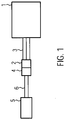
- Fig. 1 shows a schematic view of a medical monitoring system in which the connector system of the present invention can be applied.
- the monitoring system comprises a monitoring device 1 provided with a first connector 2 which is electrically connected to the monitoring device 1 by means of electrical signal and/or supply lines 3.
- the monitoring device 1 can transmit and receive electrical signals via the lines 3 to and from the first connector 2. Furthermore, the monitoring device 1 can apply a supply voltage via the lines 3.
- the first connector 2 can be releasably attached to a second connector 4 which is in electrical connection with a measurement component 5 such as a sensor, in particular a temperature sensor for detecting a temperature.
- a measurement component 5 such as a sensor, in particular a temperature sensor for detecting a temperature.
- the measurement component 5 might be a temperature sensor for sensing the body temperature of a patient which is to be monitored by the monitoring device 1.
- the temperature sensor other kinds of sensors, such as a pressure sensor and the like are applicable, too.
- the first connector 2 and the second connector 4 When the first connector 2 and the second connector 4 are coupled it is provided an electrical interconnection between the measurement component 5 and the monitoring device 1 in an appropriate manner, i.e. in a manner that allows the monitoring device 1 to operate the respective measurement component 5 e.g. by measuring a quantity to be measured.
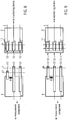
- FIG. 1 More detailed views of embodiments of the connector system comprising the first and the second connectors 2, 4 are shown in Figs 2 to 9 .
- the first and the second connector 2, 4 are provided with contact terminals A to G.
- the first connector 2 comprises first contact terminals E, F, G which are depicted for simplicity substantially adjacent to one another and are operable to provide contact on a plane 0L indicated by a dashed line crossing the first contact terminals E, F, G in Fig. 2 .
- the first contact terminals E, F, G are electrically connected with the monitoring device 1 via the electrical signal and/or supply lines 3.
- the second connector 4 comprises second contact terminals A, B, C, D.
- the second contact terminals A, B, C, D are provided in a different configuration.
- the first connector 2 is moved relative to the second connector 4 to couple the connectors 2, 4 by bringing corresponding ones of the first and second contact terminals into contact.
- the first contact terminal E comes in contact with the second contact terminal A
- the first contact terminal F comes in contact with the second contact terminal C
- the first contact terminal G comes in contact with the second contact terminal D.
- the second contact terminals A, C, D of the second connector 4 are in an arrangement which allows a contacting with the first contact terminals E, F, G of the first connector 2 which have a similar arrangement when connecting the connectors in the connecting direction CD.
- the contact terminals C and F as well as the contact terminals D and G comes into contact with each other, respectively.
- the monitoring device 1 cannot obtain a safe indication thereof whether the measurement component 5 connected is a measurement component which is allowed or capable to operate with the monitoring device 1. Therefore, measures for identification are included in the second connector 4 associated with the measurement component 5.
- the second connector 4 comprises two planes perpendicular to the connecting direction CD, a first connecting plane L1 and a second connecting plane L2. While in the first connecting plane L1 only the contact terminals A, C, D are contactable, in the second connecting plane L2 the contact terminals B, C, D are contactable.
- Contact terminal B is arranged beneath the contact terminal A in the connection direction CD such that contact terminal E contacts either contact terminal A or contact terminal B depending on the progress of the connecting movement.
- the contact terminals C and 0 are formed as long shaped contact terminals which extend form the first connecting plane L1 to the second connecting plane L2.
- the first contact terminals E, F, G are coupled with the second contact terminals A, C, D of the second connector 4 such that the contact terminals A and E, C and F and D and G comes into contact when the contact terminals E, F, G of the first connector 2 arrives at the first plane L1.
- the first connector 2 is further moved relative towards the second connector 4 such that the contact terminals E, F, G of the first connector 2 approaches the second connecting plane L2 and finally contacts the second contact terminals B, C, D provided at the second connecting plane L2.
- the connectors 2, 4 are fully connected.
- An interconnection between the measurement component and the monitoring device is then provided via the contact terminals C and F, D and G.
- the monitoring device 1 can identify the kind of measurement component 5 associated with the second connector 4 by detecting the changes of electrical states between signal and supply lines 3 while connecting the first and the second connectors 2, 4 until the final connecting position has been reached.
- a contact terminal E comes in contact with the contact terminal B of the second connector 4.
- the contact terminal A and the contact terminal C are interconnected by means of a first resistor R1 and the contact terminal B and the contact terminal C are interconnected with a second resistor R2.
- the resistors have different resistances.
- one or more of the resistors can be omitted thereby providing an infinite resistance between the respective contact terminals.
- the monitoring device 1 is sensing the resistance value between the contact terminals E and F via the respective signal lines 3 while the first connector 2 is being connected to the second connector 4.
- the monitoring 5 device 1 detects a change of the resistance from an infinite resistance (open circuit between the contact terminals E and F) to the resistance of R1 and while further connecting the connectors 2, 4 to the second connecting stage (arriving the second plane of the second connector) the detected resistance between E and F changes from the resistance value of R1 either directly to the resistance value of R2 or via a change to infinite resistance (open circuit) and thereafter from an infinite resistance to the resistance value of R2.
- the resistance profile obtained thereby and the predetermined resistance values of R1 and R2 clearly and uniquely identify the second connector 4 and consequently the measurement component 5 connected therewith.
- the monitoring device 1 may clearly identify what kind of measurement component 5 is attached.
- the monitoring device 1 can control the measurement component in an appropriate manner and the measurement values measured via the contact terminals F and G can be clearly and uniquely interpreted.
- each of the connectors 2 and 4 comprises four contact terminals.
- the first connector 2 comprises the contact terminals E, J, F, G and the second connector 4 comprises the contact terminals A, B, C, D.
- the contact terminals B, C, D of the second connector 4 are formed such they extend over the first connecting plane L1 and the second connecting plane L2.
- the contact terminal A is only contactable via the first connecting plane L1.
- the first resistance R1 is applied between the contact terminal A and the contact terminal C and the second resistance R2 is connected between the contact terminal B and the contact terminal C.
- the measurement component 5 is connected with the contact terminals C and D like in the embodiment of Fig. 2 .
- the monitoring device 1 therefore, experiences a change of the resistance between the contact terminals E and F from infinite resistance to the resistance of R2 and a change between the contact terminals J and F from infinite resistance to the resistance value of R1.
- the resistance changes are monitored and compared to a stored resistance profile indicating resistance changes to identify the measurement component associated with the second connector 4.
- the stored resistance profile indicates for each allowed second connector 4 a timely change of resistances between specific contact terminals of the first connector 2 and their respective resistance values.
- FIG. 4 A further embodiment of the connector system is shown in Fig. 4 .
- the connector system of Fig. 4 differs from the connector system as shown in Fig. 2 in that the contact terminal D of the second connector 4 is not present (contactable) in the first connecting plane L1 such that while connecting the first connector 2 and the second connector 4 an applying of the measurement component 5 to the monitoring device 1 is completed only when the connectors 2, 4 are fully coupled, i.e. the contact terminals of the first connector 2 have reached the second connecting plane L2 of the second connector 4.
- Fig. 5 an exemplary connector system is depicted.
- the contact terminals A, B are provided as a single contact terminal A which has an L-shape.
- the contact terminals E, F of the first connector 2 both contact the contact terminal A being thereby shortcut which can be detected by the monitoring device 1.
- the contact terminal F of the first connector 2 comes out of contact with the contact terminal A of the second connector 4 and comes into contact with contact terminal C of the second connector 4 while the contact terminal E of the first connector 2 remains in contact with the contact terminal A of the second connector 4.
- the resistance changes between contact terminals E, F are detected and compared to a stored resistance profile indicating resistance changes to identify the measurement component associated with the second connector 4.
- a timely change of an open loop, to a shortcut and back to an open loop between the contact terminals E, F can thereby be interpreted as a full coupling of the two connectors 2, 4.
- a further embodiment of a connector system is depicted.
- the contact terminal B of the second connector 4 can be contacted with the contact terminal E of the first connector 2 both in the first and the second connecting stage.
- the contact terminal C is only contactable by the contact terminal F of the first connector 2 in the second connecting stage and a contact terminal A is provided in the same connecting line before contact terminal C and is adapted to be contacted by the contact terminal F of the first connector 2 in the first connecting stage.
- a resistance R3 is provided between the contact terminal A and the contact terminal C a resistance R3 is provided.
- the monitoring device 1 detects in the first connecting stage via contact terminal F an electrical quantity which depends on the resistance value R3 and in the second connecting stage an electrical quantity which does not depend on the resistance value R3.
- a timely change resistance measurement via a contact terminal F does result in a resistance increased by R3 in the first connecting stage and in a resistance not increased by R3 in the following second resistance state.
- a further exemplary connector system is depicted.
- the contact terminals B, C, D of the second connector 4 can only be contacted with the respective contact terminals E, F, G of the first connector 2 in the second connecting stage.
- a common contact terminal A is provided which can be contacted by the contact terminals E, F, G substantially at the same time in the first connecting stage thereby providing a shortcut between all contact terminals E, F, G in the first connecting stage.
- the measurement component 5 is directly connected via the first and second connectors 2, 4 to the monitoring device 1 which can detect normal electrical characteristics (e.g. internal impedance) of the measurement component 5 not being influenced by a further electrical element, such as a resistance device or the like.
- the design of the connectors 2, 4 is substantially arbitrary. It is, however, essential that the first and the second connectors 2, 4 can be coupled with one another and that the connector associated with the measurement component 5 has at least two connecting planes including different arrangements of the plurality of respective contact terminals, wherein the contact terminals related to the different connecting planes are successively contacted while the connecting of the connectors progresses. Some of the second contact terminals are coupled with the measurement component 5 and other contact terminals have a connection with another of the contact terminals via a resistor or another passive electrical device.
- first contact terminals of the first connector 2 are preferably provided as sliding contacts.
- the second contact terminals of the second connector 4 are preferably provided as plane contact areas provided on a printed circuit board as a substrate or the like.
- the embodiments of Figs. 8 and 9 now provide that the first 5 connector 2 is configured as a socket and the second connector 4 configured as a plug.
- the socket of the first connector 2 has openings for receiving pins of the plug of the second connector 4.
- Inner walls of the openings 12 are provided with inner contact terminals 11 which correspond to the contact terminals E, F, G.
- the pins of the plug correspond to the second contact terminals A, C, D.
- the pins 13 have different lengths thereby defining different connecting planes as described above.
- the pins 13 of the contact terminals C and D have a first, longer length and the pin of the contact terminal A has a second shorter length thereby providing the different connecting planes L1 and L2. While connecting the plug and the socket the pins C and D firstly come into contact with the inner contact terminals 11 F and G of the socket and while further proceeding the connecting the shorter pin A comes into contact with the inner contact terminal E of the socket.
- the monitoring device 1 In the monitoring device 1, therefore, it is firstly detected the inner resistance of the measurement component between the contact terminals F and G and while further connecting the plug and the socket the resistance between the contact terminals E and F changes from infinite resistance to the resistance value of R1.
- the measurement component 5 associated with the plug can be clearly and uniquely be identified by determining the resistance profile while connecting the plug and the socket. Identification is defined by the value of the resistance R1 and the length of each of the pins A, C, D of the plug.
- the socket as the first connector 2 has openings wherein the inner contact terminals 12 are differently configured thereby providing different connecting planes L3 and L4 with respect to pins of a plug to be connected therewith. While the openings 12 of the contact terminals F and G have an inner contact terminal which can be contacted when the connecting of the pins has reached a first connecting plane L3 of the socket, the contact terminal E is recessed in the respective opening such that the respective pin of the plug can only contact when reached the second connecting plane L4. Thereby, while connecting, a respective pin A of the plug will contact the contact terminal E at a later point of time than the time the pin C and D contact the contact terminals F and G, respectively.
- resistances R1, R2 instead of resistances R1, R2 other kinds of electrical passive devices such as capacities or inductors, or active devices such as transistors and the like can be provided to provide electrically measurable quantities between the respective contact terminals.
- the electric quantities such as an impedance can e.g. be measured by applying an AC signal via the respective signal lines.
- the number of connecting planes in the second connector is not limited to two but can also be more than two.
- the number of electrical devices for providing the electrical quantity is not limited to one or two.
- the inner resistance of the measurement component 5 can be used as one of the resistances to be checked between the respective contact terminals to identify the measurement component.
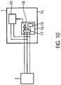
- a monitoring device 1 including an identification unit 16 for identifying the kind of measurement component 5 connected with the first connector 2.
- the identification unit 16 comprises a measurement unit 17or detecting the resistance values between the different signal lines and for establishing a time-resistance characteristics of the resistances values and its variations in time and comparing such a time-resistance characteristics by means of a comparing unit 18 with profiles prestored in a appropriate memory unit 19.
- An identification information is output by the comparing unit 18 to a monitoring unit 20 of the monitoring device which is connected to the signal lines 3 reserved for being operatively connected to the measurement component 5.
- the measurement is performed by the monitoring unit 20 depending on the identification information identifying the respective measurement component 5 connected.
Landscapes
- Physics & Mathematics (AREA)
- General Physics & Mathematics (AREA)
- Testing Of Short-Circuits, Discontinuities, Leakage, Or Incorrect Line Connections (AREA)
- Details Of Connecting Devices For Male And Female Coupling (AREA)
Claims (8)
- Zweiter Verbinder (4), der geeignet ist, mit einem ersten Verbinder (2) gekoppelt zu werden;- wobei der erste Verbinder (2) zum Koppeln einer Überwachungsvorrichtung (1) geeignet ist und mehrere erste Kontaktanschlüsse (E, F, G, J) aufweist, die im Wesentlichen nebeneinander angeordnet sind und so betrieben werden können, dass sie einen Kontakt in einer Ebene (0L) bereitstellen;- wobei der zweite Verbinder (4) zum Koppeln an eine elektrische Komponente (5) geeignet ist und mehrere zweite Kontaktanschlüsse (A, B, C, D) aufweist,wobei zwischen mindestens zwei der mehreren zweiten Kontaktanschlüssen (A, B, C, D) eine elektrische Vorrichtung (R1, R2) zum Bereitstellen einer detektierbaren elektrischen Größe angeordnet ist;
wobei der erste und der zweite Verbinder (2, 4), geeignet sind, in einem Verbindungsprozess in einer Verbindungsrichtung (CD) gekoppelt zu werden;
dadurch gekennzeichnet, dass die zweiten Kontaktanschlüsse (A, B, C, D) und die elektrische Vorrichtung (R1, R2) so angeordnet sind, dass eine erste Teilmenge (A, C, D; A, B, C, D; A, C; A, B, D; C, D) von zweiten Kontaktanschlüssen (A, B, C, D) in einer ersten Verbindungsebene (L1) senkrecht zur Verbindungsrichtung (CD) kontaktierbar ist und eine zweite Teilmenge (B, C, D; A, C, D) von zweiten Kontaktanschlüssen (A, B, C, D), die sich von der ersten Teilmenge unterscheidet, in einer zweiten Verbindungsebene (L2) senkrecht zur Verbindungsrichtung (CD) kontaktierbar ist, und zwar derart, dass während des Verbindens die ersten Kontaktanschlüsse (E, F, G, J) mit der ersten Teilmenge (A, C, D; A, B, C, D; A, C; A, B, D; C, D) der mehreren zweiten Kontaktanschlüsse (A, B, C, D) in einer ersten Verbindungsstufe in Kontakt kommen, in der die ersten Kontaktanschlüsse (E, F, G, J) des ersten Verbinders (2) in der ersten Verbindungsebene (L1) positioniert sind, und während das Verbinden weiter fortschreitet, die ersten Kontaktanschlüsse (E, F, G, J) mit der zweiten Teilmenge (B, C, D; A, C, D) der zweiten Kontaktanschlüsse (A, B, C, D) in einer zweiten Verbindungsstufe in Kontakt kommen, in der die ersten Kontaktanschlüsse (E, F, G, J) des ersten Verbinders (2) in der zweiten Verbindungsebene (L2) positioniert sind, und
dass eine erste elektrische Größe in der ersten Verbindungsstufe zwischen zwei der ersten Kontaktanschlüsse (E, F, G, J) vorgesehen ist, die sich von einer elektrischen Größe zwischen den beiden genannten ersten Kontaktanschlüssen (E, F, G, J) in einem entkoppelten Zustand der Verbinder (2, 4) unterscheidet, und eine zweite elektrische Größe, die in der zweiten Verbindungsstufe zwischen mindestens zwei der ersten Kontaktanschlüsse (E, F, G, J) vorgesehen ist und sich von der ersten elektrischen Größe in der ersten Verbindungsstufe unterscheidet, durch die mit dem ersten Verbinder (2) gekoppelte Überwachungsvorrichtung (1) detektierbar sind,
und dass die erste oder zweite detektierbare elektrische Größe durch die elektrische Vorrichtung (R1, R2) bereitgestellt wird. - Verbindungssystem, enthaltend:einen ersten Verbinder (2), der zum Koppeln mit einer Überwachungsvorrichtung (1) geeignet ist und mehrere erste Kontaktanschlüsse (E, F, G, J) aufweist, die im Wesentlichen nebeneinander angeordnet sind und so betrieben werden können, dass sie einen Kontakt in einer Ebene (0L) bereitstellen; undeinen zweiten Verbinder (4) gemäß Anspruch 1;wobei der erste und der zweite Verbinder (2, 4), geeignet sind, in einem Verbindungsprozess in der Verbindungsrichtung (CD) gekoppelt zu werden.
- Verbindungssystem nach Anspruch 2; wobei die elektrische Vorrichtung (R1, R2) mindestens eines von einem Widerstand, einer Kapazität und einer Induktivität ist.
- Verbindungssystem nach Anspruch 2, wobei der zweite Verbinder (4) so konfiguriert ist, dass er zwei der zweiten Kontaktanschlüsse (A, B; A, C) derart bereitstellt, dass einer (A) der beiden zweiten Kontaktanschlüsse (A, B; A, C) durch einen jeweiligen (E; F) der ersten Kontaktanschlüsse (E, F, G, J) in der ersten Verbindungsstufe kontaktierbar ist und der andere (B; C) der beiden zweiten Kontaktanschlüsse (A, B; A, C) durch den jeweiligen einen ersten Kontaktanschluss (E; F) in der zweiten Verbindungsstufe kontaktierbar ist.
- Verbindungssystem nach Anspruch 4, wobei die beiden zweiten Kontaktanschlüsse (A, B, C, D) jeweils mit einer elektrischen Vorrichtung (R1, R2) gekoppelt und so beabstandet sind, dass während des Verbindens der eine erste Kontaktanschluss (E) von den beiden zweiten Kontaktanschlüssen (A, B) zwischen der ersten und der zweiten Verbindungsstufe isoliert ist.
- Elektrische Komponentenanordnung enthaltend eine elektrische Komponente (5) und den zweiten Verbinder (4) gemäß Anspruch 1, der mit der elektrischen Komponente (5) gekoppelt ist.
- Elektrische Komponentenanordnung enthaltend eine Überwachungsvorrichtung (1) zum Koppeln mit einer elektrischen Komponente und einen ersten Verbinder (2), der mit der Überwachungsvorrichtung (1) über Signalleitungen (3) gekoppelt ist, wobei der erste Verbinder (2) geeignet ist, mit einem zweiten Verbinder (4) gemäß Anspruch 1 gekoppelt zu werden, wobei der erste Verbinder (2) mehrere erste Kontaktanschlüsse (E, F, G, J) aufweist, die im Wesentlichen nebeneinander angeordnet sind und betrieben werden können, dass sie einen Kontakt in einer Ebene (0L) bereitstellen, dadurch gekennzeichnet, dass die Überwachungsvorrichtung (1) ausgebildet ist, um die Art der Messkomponente (5) zu identifizieren, die mit dem ersten Verbinder (2) verbunden ist, und enthält:- eine Identifikationseinheit (16) zum Erfassen zeitlicher Eigenschaften einer elektrischen Größe zwischen den Signalleitungen (3), die mit dem ersten Verbinder (2) verbunden sind;- eine Vergleichereinheit (18) zum Vergleichen der erfassten zeitlichen Eigenschaften der elektrischen Größe mit einem vorgespeicherten Profil;- eine Überwachungseinheit (20) zum Betreiben der elektrischen Komponente (5) über den ersten Verbinder (2) in Abhängigkeit von dem Ergebnis des Vergleichs der Vergleichereinheit (18).
- Verfahren zum Betreiben einer elektrischen Komponente (5) über einen ersten Verbinder (2) und einen zweiten Verbinder (4) gemäß Anspruch 1, enthaltend die folgenden Schritte:- Verbinden des ersten Verbinders (2) mit dem zweiten Verbinder (4), wobei der zweite Verbinder (4) mit der elektrischen Komponente (5) gekoppelt ist,- Erfassen zeitlicher Eigenschaften elektrischer Größen auf Signalleitungen (3), die mit dem ersten Verbinder (2) gekoppelt sind;- Vergleichen der erfassten zeitlichen Eigenschaften der elektrischen Größen mit einem vorgespeicherten Profil;- Betreiben der elektrischen Komponente (5) über den ersten Verbinder (2) in Abhängigkeit von dem Ergebnis des Vergleichsschrittes.
Applications Claiming Priority (2)
| Application Number | Priority Date | Filing Date | Title |
|---|---|---|---|
| DE102007022210A DE102007022210B3 (de) | 2007-05-11 | 2007-05-11 | Mehrstufiges Verbindersystem für medizinische Verwendung |
| PCT/EP2008/003625 WO2008138515A1 (en) | 2007-05-11 | 2008-05-06 | Multilevel connector system |
Publications (2)
| Publication Number | Publication Date |
|---|---|
| EP2147486A1 EP2147486A1 (de) | 2010-01-27 |
| EP2147486B1 true EP2147486B1 (de) | 2021-01-06 |
Family
ID=39563587
Family Applications (1)
| Application Number | Title | Priority Date | Filing Date |
|---|---|---|---|
| EP08749347.4A Active EP2147486B1 (de) | 2007-05-11 | 2008-05-06 | Verbindungsvorrichtung |
Country Status (6)
| Country | Link |
|---|---|
| US (2) | US8597048B2 (de) |
| EP (1) | EP2147486B1 (de) |
| CN (1) | CN101785154B (de) |
| CA (1) | CA2687152A1 (de) |
| DE (1) | DE102007022210B3 (de) |
| WO (1) | WO2008138515A1 (de) |
Families Citing this family (7)
| Publication number | Priority date | Publication date | Assignee | Title |
|---|---|---|---|---|
| DE102009029042B4 (de) * | 2009-08-31 | 2015-05-28 | Endress + Hauser Gmbh + Co. Kg | Messgerät zur Bestimmung mindestens einer physikalischen, chemischen, oder biologischen Prozessgröße eines Mediums |
| US20130017732A1 (en) * | 2011-01-15 | 2013-01-17 | Parke Eugene James | Method and apparatus for detecting improper connector seating or engagement |
| DE102014007637A1 (de) * | 2014-05-15 | 2015-11-19 | e.solutions GmbH | Elektrische Verbindungsvorrichtung |
| EP3345169A1 (de) * | 2015-09-01 | 2018-07-11 | Philips Lighting Holding B.V. | System und verfahren zur überwachung des anschlusses einer steckbaren beleuchtungseinheit an einer steckdose |
| US9935668B1 (en) | 2017-02-16 | 2018-04-03 | Datron World Communications, Inc. | Detachment mechanism and indicator for mobile mount portable radio and method for the same |
| DE102017002547B3 (de) * | 2017-03-16 | 2018-02-22 | Drägerwerk AG & Co. KGaA | Vorrichtung zur elektrisch leitenden Kontaktierung eines Hitzdrahtsensors und Medizingerät mit einer solchen Vorrichtung |
| US11637392B2 (en) * | 2020-01-07 | 2023-04-25 | Hamilton Sundstrand Corporation | Electrical mating systems |
Family Cites Families (18)
| Publication number | Priority date | Publication date | Assignee | Title |
|---|---|---|---|---|
| JPH01132076U (de) | 1988-03-04 | 1989-09-07 | ||
| US4949035A (en) | 1989-01-06 | 1990-08-14 | Digital Equipment Corporation | Connector alignment verification and monitoring system |
| US5203004A (en) * | 1990-01-08 | 1993-04-13 | Tandem Computers Incorporated | Multi-board system having electronic keying and preventing power to improperly connected plug-in board with improperly configured diode connections |
| US5146172A (en) * | 1990-08-15 | 1992-09-08 | Sundstrand Corp. | Engine identification system |
| JPH0454162U (de) | 1990-09-14 | 1992-05-08 | ||
| US5336934A (en) | 1992-12-17 | 1994-08-09 | Ford Motor Company | Electrical connection and interlock circuit system for vehicle electric drive |
| JPH0757062A (ja) | 1993-06-30 | 1995-03-03 | Ricoh Co Ltd | 電子機器 |
| SE9402297D0 (sv) | 1994-06-29 | 1994-06-29 | Siemens Elema Ab | Indikeringsanordning |
| TW281724B (en) * | 1995-03-06 | 1996-07-21 | Advanced Micro Devices Inc | Apparatus and method to uniquely identify similarly connected electrical devices |
| CA2212951C (fr) * | 1995-03-22 | 2003-02-18 | Framatome Connectors International | Connecteur pour appareil lecteur de carte a microcircuit |
| JPH0917510A (ja) * | 1995-06-29 | 1997-01-17 | Sumitomo Wiring Syst Ltd | 嵌合検知コネクタ |
| DE19631425A1 (de) * | 1996-08-06 | 1998-02-12 | Wolf & Beck Gmbh Dr | Verfahren zur Identifikation von an Meß- oder Werkzeugmaschinen austauschbar angeordneten Zubehörteilen sowie Identifikator zur Verfahrensdurchführung |
| US6517375B2 (en) * | 2000-01-25 | 2003-02-11 | Compaq Information Technologies Group, L.P. | Technique for identifying multiple circuit components |
| US6411053B1 (en) * | 2000-09-26 | 2002-06-25 | Penny & Giles Drives Technology Limited | Electrical system |
| US6986071B2 (en) * | 2002-02-01 | 2006-01-10 | Powerdsine, Ltd. | Detecting network power connection status using AC signals |
| US20030146764A1 (en) | 2002-02-05 | 2003-08-07 | Chun-Liang Lee | Protector for blade module of information processing apparatus |
| CN1211893C (zh) * | 2002-03-20 | 2005-07-20 | 建碁股份有限公司 | 具保护功能的电路板及保护电路板的方法 |
| US7985330B2 (en) * | 2005-12-30 | 2011-07-26 | Medtronic Minimed, Inc. | Method and system for detecting age, hydration, and functional states of sensors using electrochemical impedance spectroscopy |
-
2007
- 2007-05-11 DE DE102007022210A patent/DE102007022210B3/de active Active
-
2008
- 2008-05-05 US US12/599,473 patent/US8597048B2/en active Active
- 2008-05-06 EP EP08749347.4A patent/EP2147486B1/de active Active
- 2008-05-06 CN CN2008800230839A patent/CN101785154B/zh active Active
- 2008-05-06 WO PCT/EP2008/003625 patent/WO2008138515A1/en not_active Ceased
- 2008-05-06 CA CA002687152A patent/CA2687152A1/en not_active Abandoned
-
2013
- 2013-12-02 US US14/094,615 patent/US20140239937A1/en not_active Abandoned
Non-Patent Citations (1)
| Title |
|---|
| None * |
Also Published As
| Publication number | Publication date |
|---|---|
| CN101785154A (zh) | 2010-07-21 |
| US20110199095A1 (en) | 2011-08-18 |
| WO2008138515A1 (en) | 2008-11-20 |
| DE102007022210B3 (de) | 2008-12-18 |
| US8597048B2 (en) | 2013-12-03 |
| CN101785154B (zh) | 2013-11-13 |
| US20140239937A1 (en) | 2014-08-28 |
| CA2687152A1 (en) | 2008-11-20 |
| EP2147486A1 (de) | 2010-01-27 |
Similar Documents
| Publication | Publication Date | Title |
|---|---|---|
| US20140239937A1 (en) | Multilevel Connector System For Medical Use | |
| CN110392642B (zh) | 电动车辆耦合器接触的热管理 | |
| US9857396B2 (en) | Device for measuring at least one physical quantity of an electric installation | |
| CN110595524B (zh) | 传感器饱和故障检测 | |
| KR20160075310A (ko) | 자동 데이터 버스 와이어 무결성 검증 디바이스 | |
| US20110167919A1 (en) | Vacuum measuring device with interchangeable sensors | |
| EP2921242A1 (de) | Pressfitting | |
| KR20250056979A (ko) | 충전 플러그 커넥터의 복수의 충전 접촉의 해당 온도를 모니터링하기 위한 전기 회로 | |
| KR20070121720A (ko) | 센서 장치 | |
| CN112291108B (zh) | 一种以太网交换机中网络端口连接状态的检测方法 | |
| CN205539299U (zh) | 可测试连接正确性的检测装置 | |
| JP2001050996A (ja) | プローブ接触状態検出方法およびプローブ接触状態検出装置 | |
| CN217112603U (zh) | 一种测试电路板及测试机构 | |
| CN117147988A (zh) | 测试电气部件的测试器、测试系统和方法 | |
| CN105098418B (zh) | 电气连接装置 | |
| TWI749548B (zh) | 一種插針偏位的檢測系統與檢測方法 | |
| KR101428661B1 (ko) | 검사 장치 | |
| KR101002573B1 (ko) | 슬롯진단장치 | |
| US10996308B2 (en) | Apparatus and method for authentication of electronic device test stations | |
| CN106124938A (zh) | 电子模块以及用于对电子模块进行检查的方法和装置 | |
| JPH0275087A (ja) | 磁気ラインセンサ | |
| US20250189573A1 (en) | Testing system for detecting a fault and a location of the fault | |
| US20210385305A1 (en) | Communication device with connection detection | |
| EP4542093A1 (de) | Systeme und verfahren zur bestimmung von ventilflattern | |
| WO1989010639A1 (en) | Static-free interrogating connector for electric components |
Legal Events
| Date | Code | Title | Description |
|---|---|---|---|
| PUAI | Public reference made under article 153(3) epc to a published international application that has entered the european phase |
Free format text: ORIGINAL CODE: 0009012 |
|
| 17P | Request for examination filed |
Effective date: 20091211 |
|
| AK | Designated contracting states |
Kind code of ref document: A1 Designated state(s): AT BE BG CH CY CZ DE DK EE ES FI FR GB GR HR HU IE IS IT LI LT LU LV MC MT NL NO PL PT RO SE SI SK TR |
|
| AX | Request for extension of the european patent |
Extension state: AL BA MK RS |
|
| DAX | Request for extension of the european patent (deleted) | ||
| 17Q | First examination report despatched |
Effective date: 20110713 |
|
| STAA | Information on the status of an ep patent application or granted ep patent |
Free format text: STATUS: EXAMINATION IS IN PROGRESS |
|
| GRAP | Despatch of communication of intention to grant a patent |
Free format text: ORIGINAL CODE: EPIDOSNIGR1 |
|
| STAA | Information on the status of an ep patent application or granted ep patent |
Free format text: STATUS: GRANT OF PATENT IS INTENDED |
|
| RIC1 | Information provided on ipc code assigned before grant |
Ipc: H01R 13/66 20060101ALN20200609BHEP Ipc: H01R 105/00 20060101ALN20200609BHEP Ipc: H01R 13/641 20060101AFI20200609BHEP Ipc: H01R 107/00 20060101ALN20200609BHEP |
|
| RIC1 | Information provided on ipc code assigned before grant |
Ipc: H01R 107/00 20060101ALN20200616BHEP Ipc: H01R 13/641 20060101AFI20200616BHEP Ipc: H01R 13/66 20060101ALN20200616BHEP Ipc: H01R 105/00 20060101ALN20200616BHEP |
|
| INTG | Intention to grant announced |
Effective date: 20200630 |
|
| GRAJ | Information related to disapproval of communication of intention to grant by the applicant or resumption of examination proceedings by the epo deleted |
Free format text: ORIGINAL CODE: EPIDOSDIGR1 |
|
| STAA | Information on the status of an ep patent application or granted ep patent |
Free format text: STATUS: EXAMINATION IS IN PROGRESS |
|
| REG | Reference to a national code |
Ref country code: DE Ref legal event code: R079 Ref document number: 602008063632 Country of ref document: DE Free format text: PREVIOUS MAIN CLASS: H01R0013640000 Ipc: H01R0013641000 |
|
| GRAR | Information related to intention to grant a patent recorded |
Free format text: ORIGINAL CODE: EPIDOSNIGR71 |
|
| GRAS | Grant fee paid |
Free format text: ORIGINAL CODE: EPIDOSNIGR3 |
|
| STAA | Information on the status of an ep patent application or granted ep patent |
Free format text: STATUS: GRANT OF PATENT IS INTENDED |
|
| GRAA | (expected) grant |
Free format text: ORIGINAL CODE: 0009210 |
|
| STAA | Information on the status of an ep patent application or granted ep patent |
Free format text: STATUS: THE PATENT HAS BEEN GRANTED |
|
| INTC | Intention to grant announced (deleted) | ||
| RIC1 | Information provided on ipc code assigned before grant |
Ipc: H01R 13/66 20060101ALN20201117BHEP Ipc: H01R 107/00 20060101ALN20201117BHEP Ipc: H01R 105/00 20060101ALN20201117BHEP Ipc: H01R 13/641 20060101AFI20201117BHEP |
|
| INTG | Intention to grant announced |
Effective date: 20201126 |
|
| AK | Designated contracting states |
Kind code of ref document: B1 Designated state(s): AT BE BG CH CY CZ DE DK EE ES FI FR GB GR HR HU IE IS IT LI LT LU LV MC MT NL NO PL PT RO SE SI SK TR |
|
| REG | Reference to a national code |
Ref country code: GB Ref legal event code: FG4D |
|
| REG | Reference to a national code |
Ref country code: AT Ref legal event code: REF Ref document number: 1353392 Country of ref document: AT Kind code of ref document: T Effective date: 20210115 Ref country code: CH Ref legal event code: EP |
|
| REG | Reference to a national code |
Ref country code: DE Ref legal event code: R096 Ref document number: 602008063632 Country of ref document: DE |
|
| REG | Reference to a national code |
Ref country code: IE Ref legal event code: FG4D |
|
| REG | Reference to a national code |
Ref country code: NL Ref legal event code: MP Effective date: 20210106 |
|
| REG | Reference to a national code |
Ref country code: AT Ref legal event code: MK05 Ref document number: 1353392 Country of ref document: AT Kind code of ref document: T Effective date: 20210106 |
|
| REG | Reference to a national code |
Ref country code: LT Ref legal event code: MG9D |
|
| PG25 | Lapsed in a contracting state [announced via postgrant information from national office to epo] |
Ref country code: HR Free format text: LAPSE BECAUSE OF FAILURE TO SUBMIT A TRANSLATION OF THE DESCRIPTION OR TO PAY THE FEE WITHIN THE PRESCRIBED TIME-LIMIT Effective date: 20210106 Ref country code: FI Free format text: LAPSE BECAUSE OF FAILURE TO SUBMIT A TRANSLATION OF THE DESCRIPTION OR TO PAY THE FEE WITHIN THE PRESCRIBED TIME-LIMIT Effective date: 20210106 Ref country code: GR Free format text: LAPSE BECAUSE OF FAILURE TO SUBMIT A TRANSLATION OF THE DESCRIPTION OR TO PAY THE FEE WITHIN THE PRESCRIBED TIME-LIMIT Effective date: 20210407 Ref country code: LT Free format text: LAPSE BECAUSE OF FAILURE TO SUBMIT A TRANSLATION OF THE DESCRIPTION OR TO PAY THE FEE WITHIN THE PRESCRIBED TIME-LIMIT Effective date: 20210106 Ref country code: BG Free format text: LAPSE BECAUSE OF FAILURE TO SUBMIT A TRANSLATION OF THE DESCRIPTION OR TO PAY THE FEE WITHIN THE PRESCRIBED TIME-LIMIT Effective date: 20210406 Ref country code: NL Free format text: LAPSE BECAUSE OF FAILURE TO SUBMIT A TRANSLATION OF THE DESCRIPTION OR TO PAY THE FEE WITHIN THE PRESCRIBED TIME-LIMIT Effective date: 20210106 Ref country code: NO Free format text: LAPSE BECAUSE OF FAILURE TO SUBMIT A TRANSLATION OF THE DESCRIPTION OR TO PAY THE FEE WITHIN THE PRESCRIBED TIME-LIMIT Effective date: 20210406 Ref country code: PT Free format text: LAPSE BECAUSE OF FAILURE TO SUBMIT A TRANSLATION OF THE DESCRIPTION OR TO PAY THE FEE WITHIN THE PRESCRIBED TIME-LIMIT Effective date: 20210506 |
|
| PG25 | Lapsed in a contracting state [announced via postgrant information from national office to epo] |
Ref country code: PL Free format text: LAPSE BECAUSE OF FAILURE TO SUBMIT A TRANSLATION OF THE DESCRIPTION OR TO PAY THE FEE WITHIN THE PRESCRIBED TIME-LIMIT Effective date: 20210106 Ref country code: LV Free format text: LAPSE BECAUSE OF FAILURE TO SUBMIT A TRANSLATION OF THE DESCRIPTION OR TO PAY THE FEE WITHIN THE PRESCRIBED TIME-LIMIT Effective date: 20210106 Ref country code: AT Free format text: LAPSE BECAUSE OF FAILURE TO SUBMIT A TRANSLATION OF THE DESCRIPTION OR TO PAY THE FEE WITHIN THE PRESCRIBED TIME-LIMIT Effective date: 20210106 Ref country code: SE Free format text: LAPSE BECAUSE OF FAILURE TO SUBMIT A TRANSLATION OF THE DESCRIPTION OR TO PAY THE FEE WITHIN THE PRESCRIBED TIME-LIMIT Effective date: 20210106 |
|
| PG25 | Lapsed in a contracting state [announced via postgrant information from national office to epo] |
Ref country code: IS Free format text: LAPSE BECAUSE OF FAILURE TO SUBMIT A TRANSLATION OF THE DESCRIPTION OR TO PAY THE FEE WITHIN THE PRESCRIBED TIME-LIMIT Effective date: 20210506 |
|
| REG | Reference to a national code |
Ref country code: DE Ref legal event code: R097 Ref document number: 602008063632 Country of ref document: DE |
|
| PG25 | Lapsed in a contracting state [announced via postgrant information from national office to epo] |
Ref country code: CZ Free format text: LAPSE BECAUSE OF FAILURE TO SUBMIT A TRANSLATION OF THE DESCRIPTION OR TO PAY THE FEE WITHIN THE PRESCRIBED TIME-LIMIT Effective date: 20210106 Ref country code: EE Free format text: LAPSE BECAUSE OF FAILURE TO SUBMIT A TRANSLATION OF THE DESCRIPTION OR TO PAY THE FEE WITHIN THE PRESCRIBED TIME-LIMIT Effective date: 20210106 |
|
| PLBE | No opposition filed within time limit |
Free format text: ORIGINAL CODE: 0009261 |
|
| STAA | Information on the status of an ep patent application or granted ep patent |
Free format text: STATUS: NO OPPOSITION FILED WITHIN TIME LIMIT |
|
| PG25 | Lapsed in a contracting state [announced via postgrant information from national office to epo] |
Ref country code: SK Free format text: LAPSE BECAUSE OF FAILURE TO SUBMIT A TRANSLATION OF THE DESCRIPTION OR TO PAY THE FEE WITHIN THE PRESCRIBED TIME-LIMIT Effective date: 20210106 Ref country code: DK Free format text: LAPSE BECAUSE OF FAILURE TO SUBMIT A TRANSLATION OF THE DESCRIPTION OR TO PAY THE FEE WITHIN THE PRESCRIBED TIME-LIMIT Effective date: 20210106 Ref country code: ES Free format text: LAPSE BECAUSE OF FAILURE TO SUBMIT A TRANSLATION OF THE DESCRIPTION OR TO PAY THE FEE WITHIN THE PRESCRIBED TIME-LIMIT Effective date: 20210106 Ref country code: RO Free format text: LAPSE BECAUSE OF FAILURE TO SUBMIT A TRANSLATION OF THE DESCRIPTION OR TO PAY THE FEE WITHIN THE PRESCRIBED TIME-LIMIT Effective date: 20210106 |
|
| 26N | No opposition filed |
Effective date: 20211007 |
|
| REG | Reference to a national code |
Ref country code: CH Ref legal event code: PL |
|
| GBPC | Gb: european patent ceased through non-payment of renewal fee |
Effective date: 20210506 |
|
| PG25 | Lapsed in a contracting state [announced via postgrant information from national office to epo] |
Ref country code: LI Free format text: LAPSE BECAUSE OF NON-PAYMENT OF DUE FEES Effective date: 20210531 Ref country code: LU Free format text: LAPSE BECAUSE OF NON-PAYMENT OF DUE FEES Effective date: 20210506 Ref country code: MC Free format text: LAPSE BECAUSE OF FAILURE TO SUBMIT A TRANSLATION OF THE DESCRIPTION OR TO PAY THE FEE WITHIN THE PRESCRIBED TIME-LIMIT Effective date: 20210106 Ref country code: CH Free format text: LAPSE BECAUSE OF NON-PAYMENT OF DUE FEES Effective date: 20210531 |
|
| REG | Reference to a national code |
Ref country code: BE Ref legal event code: MM Effective date: 20210531 |
|
| PG25 | Lapsed in a contracting state [announced via postgrant information from national office to epo] |
Ref country code: SI Free format text: LAPSE BECAUSE OF FAILURE TO SUBMIT A TRANSLATION OF THE DESCRIPTION OR TO PAY THE FEE WITHIN THE PRESCRIBED TIME-LIMIT Effective date: 20210106 |
|
| PG25 | Lapsed in a contracting state [announced via postgrant information from national office to epo] |
Ref country code: IT Free format text: LAPSE BECAUSE OF FAILURE TO SUBMIT A TRANSLATION OF THE DESCRIPTION OR TO PAY THE FEE WITHIN THE PRESCRIBED TIME-LIMIT Effective date: 20210106 Ref country code: IE Free format text: LAPSE BECAUSE OF NON-PAYMENT OF DUE FEES Effective date: 20210506 Ref country code: GB Free format text: LAPSE BECAUSE OF NON-PAYMENT OF DUE FEES Effective date: 20210506 |
|
| PG25 | Lapsed in a contracting state [announced via postgrant information from national office to epo] |
Ref country code: IS Free format text: LAPSE BECAUSE OF FAILURE TO SUBMIT A TRANSLATION OF THE DESCRIPTION OR TO PAY THE FEE WITHIN THE PRESCRIBED TIME-LIMIT Effective date: 20210506 Ref country code: FR Free format text: LAPSE BECAUSE OF NON-PAYMENT OF DUE FEES Effective date: 20210531 |
|
| PG25 | Lapsed in a contracting state [announced via postgrant information from national office to epo] |
Ref country code: BE Free format text: LAPSE BECAUSE OF NON-PAYMENT OF DUE FEES Effective date: 20210531 |
|
| PG25 | Lapsed in a contracting state [announced via postgrant information from national office to epo] |
Ref country code: HU Free format text: LAPSE BECAUSE OF FAILURE TO SUBMIT A TRANSLATION OF THE DESCRIPTION OR TO PAY THE FEE WITHIN THE PRESCRIBED TIME-LIMIT; INVALID AB INITIO Effective date: 20080506 Ref country code: CY Free format text: LAPSE BECAUSE OF FAILURE TO SUBMIT A TRANSLATION OF THE DESCRIPTION OR TO PAY THE FEE WITHIN THE PRESCRIBED TIME-LIMIT Effective date: 20210106 |
|
| P01 | Opt-out of the competence of the unified patent court (upc) registered |
Effective date: 20230525 |
|
| PG25 | Lapsed in a contracting state [announced via postgrant information from national office to epo] |
Ref country code: TR Free format text: LAPSE BECAUSE OF FAILURE TO SUBMIT A TRANSLATION OF THE DESCRIPTION OR TO PAY THE FEE WITHIN THE PRESCRIBED TIME-LIMIT Effective date: 20210106 |
|
| PG25 | Lapsed in a contracting state [announced via postgrant information from national office to epo] |
Ref country code: MT Free format text: LAPSE BECAUSE OF FAILURE TO SUBMIT A TRANSLATION OF THE DESCRIPTION OR TO PAY THE FEE WITHIN THE PRESCRIBED TIME-LIMIT Effective date: 20210106 |
|
| PGFP | Annual fee paid to national office [announced via postgrant information from national office to epo] |
Ref country code: DE Payment date: 20250423 Year of fee payment: 18 |