EP2147698B1 - Ultraschallbehandlungskopf für eine Vorrichtung zur Behandlung eines Patienten mit Ultraschall - Google Patents
Ultraschallbehandlungskopf für eine Vorrichtung zur Behandlung eines Patienten mit Ultraschall Download PDFInfo
- Publication number
- EP2147698B1 EP2147698B1 EP08161003.2A EP08161003A EP2147698B1 EP 2147698 B1 EP2147698 B1 EP 2147698B1 EP 08161003 A EP08161003 A EP 08161003A EP 2147698 B1 EP2147698 B1 EP 2147698B1
- Authority
- EP
- European Patent Office
- Prior art keywords
- treatment head
- active element
- gel pad
- ultrasound
- positioning ring
- Prior art date
- Legal status (The legal status is an assumption and is not a legal conclusion. Google has not performed a legal analysis and makes no representation as to the accuracy of the status listed.)
- Active
Links
Images


Classifications
-
- A—HUMAN NECESSITIES
- A61—MEDICAL OR VETERINARY SCIENCE; HYGIENE
- A61N—ELECTROTHERAPY; MAGNETOTHERAPY; RADIATION THERAPY; ULTRASOUND THERAPY
- A61N7/00—Ultrasound therapy
-
- A—HUMAN NECESSITIES
- A61—MEDICAL OR VETERINARY SCIENCE; HYGIENE
- A61B—DIAGNOSIS; SURGERY; IDENTIFICATION
- A61B5/00—Measuring for diagnostic purposes; Identification of persons
- A61B5/68—Arrangements of detecting, measuring or recording means, e.g. sensors, in relation to patient
- A61B5/6801—Arrangements of detecting, measuring or recording means, e.g. sensors, in relation to patient specially adapted to be attached to or worn on the body surface
- A61B5/683—Means for maintaining contact with the body
- A61B5/6834—Means for maintaining contact with the body using vacuum
-
- A—HUMAN NECESSITIES
- A61—MEDICAL OR VETERINARY SCIENCE; HYGIENE
- A61B—DIAGNOSIS; SURGERY; IDENTIFICATION
- A61B17/00—Surgical instruments, devices or methods
- A61B17/22—Implements for squeezing-off ulcers or the like on inner organs of the body; Implements for scraping-out cavities of body organs, e.g. bones; for invasive removal or destruction of calculus using mechanical vibrations; for removing obstructions in blood vessels, not otherwise provided for
- A61B17/225—Implements for squeezing-off ulcers or the like on inner organs of the body; Implements for scraping-out cavities of body organs, e.g. bones; for invasive removal or destruction of calculus using mechanical vibrations; for removing obstructions in blood vessels, not otherwise provided for for extracorporeal shock wave lithotripsy [ESWL], e.g. by using ultrasonic waves
- A61B17/2251—Implements for squeezing-off ulcers or the like on inner organs of the body; Implements for scraping-out cavities of body organs, e.g. bones; for invasive removal or destruction of calculus using mechanical vibrations; for removing obstructions in blood vessels, not otherwise provided for for extracorporeal shock wave lithotripsy [ESWL], e.g. by using ultrasonic waves characterised by coupling elements between the apparatus, e.g. shock wave apparatus or locating means, and the patient, e.g. details of bags, pressure control of bag on patient
- A61B2017/2253—Implements for squeezing-off ulcers or the like on inner organs of the body; Implements for scraping-out cavities of body organs, e.g. bones; for invasive removal or destruction of calculus using mechanical vibrations; for removing obstructions in blood vessels, not otherwise provided for for extracorporeal shock wave lithotripsy [ESWL], e.g. by using ultrasonic waves characterised by coupling elements between the apparatus, e.g. shock wave apparatus or locating means, and the patient, e.g. details of bags, pressure control of bag on patient using a coupling gel or liquid
Definitions
- the invention relates to an ultrasound treatment head for an apparatus for treating a patient with ultrasound, comprising at least one active element for converting an electric signal into ultrasound, a vacuum cup having an upper part and a lower part, wherein the active element is mounted in the upper part and the vacuum cup provides a vacuum chamber with a holding space for a gel pad.
- An ultrasound treatment head of this type is known from WO2006/091093 .
- This known ultrasound treatment head can be fixed to the part of the patient's body that is to be treated in a relatively simple manner by using an underpressure that is generated in the vacuum cup by a vacuum pump which can be part of the apparatus for treating a patient with ultrasound.
- the person in attendance does not need to stay with the patient during the treatment.
- the acoustic coupling between the active element and the part of the body that is to be treated depends on the fixation of the treatment head on the body part and the effectiveness of the coupling medium, generally water, provided by the gel pad.
- the percentage of the coupling medium in the gel pad should be high.
- a high percentage of coupling medium results in a very slippery gel pad surface, so that in the known treatment head it is very difficult if not impossible to keep the gel pad located between the active element and the body part of the patient during a treatment.
- the object of the invention is to provide an improved ultrasound treatment head of the above kind.
- the ultrasound wound care device comprises a generator, an ultrasound transducer, an ultrasound horn, and a cavitation chamber.
- the device may further comprise a fluid, non- atomized, coupling medium.
- Ultrasound entering the cavitation chamber induces cavitations within the coupling medium, providing therapeutic benefits to the wound being treated.
- the ultrasound entering the cavitation, chamber is also transmitted through the coupling medium to the wound, providing direct therapeutic benefits to the wound
- US 2005096547 discloses an accommodative standoff holder 10 which can be used for both diagnostic and therapeutic ultrasound.
- the described standoff holder 10 has the ability to be mounted on and utilized with transducers 20 of different sizes and shapes.
- the standoff holder 10 includes a gel insert 26 which is removable and self adjusting assuring contact between a human body, an animal, or other object and the acoustic window 22 of a transducer 22. Further, a gel insert 26 and method of making gel inserts 26 from a gel pad 24 is described.
- the ultrasound treatment head according to claim 1 is provided.
- an ultrasound treatment head in which the positioning ring provides for a fixed location of the gel pad as desired between the active element and the body part during the complete treatment, wherein the spring suspension of the active element in the upper part allows the active element to be pressed against the body part of the patient to be treated with the gel pad being located between the active element and this body part.
- the positioning ring guarantees that the gel pad will not be displaced from its desired location by the underpressure generated within the vacuum chamber and/or the force pressing the active element with the gel pad against the body part to be treated.
- the disclosure furthermore provides an ultrasound treatment head according to the invention, with a gel pad having a disc shape with a diameter smaller than the inner diameter of the positioning ring and a thickness larger than the protruding length of the positioning ring.
- the line 8 is configured as a combination of a vacuum line 11 and an electric line 12.
- the electric line 12 is sealingly passed through the mounting disc 9 to the active element 2.
- the electric line 12 provides the electrical connection between the electronic components, which are known per se, and the ultrasound crystal that forms part of the active element 2. These components are not shown in the drawing.
- the treatment head 1 is further provided with a vacuum cup 13 having an upper part 14 and a lower part 15.
- the upper part 14 has a side wall with a semi-circular cross-section and the lower part 15 has a bell shape, i.e. the side wall of the lower part 15 gradually flares outwardly in a mainly circular path in cross-section.
- the upper and lower parts 14,15 are interconnected through an intermediate stiffening section 16.
- the parts 14, 15 and section 16 are integrally made of a deformable material, such as silicone rubber.
- the side wall thickness of the upper part 14 is less than the side wall thickness of the lower part 15.
- the carrier 6 with the active element 2 is mounted in the upper wall of the upper part 14, wherein the connecting element 7 of the carrier 6 projects out of a section 17 of the upper wall partially enclosing the carrier 6.
- the upper part 14 is adapted to act as a spring suspension for the active element 2 due to the side wall thickness of the upper part 14 being less than the side wall thickness of the lower part 15.
- the upper wall with the active element 2 can move downwardly and in this manner the active element 2 can be lowered into the lower part 15 of the vacuum cup 13. This means that the side wall of the upper part 14 folds downwardly when an underpressure is generated within the vacuum cup 13, wherein this side wall acts as a spring.
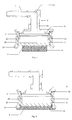
- the vacuum cup 13 encloses a vacuum chamber 18 with a holding space for a gel pad 19 indicated in Fig. 2 by a dashed line.
- This gel pad 19 contains a high percentage of water as acoustic coupling medium, so that the surface of the gel pad is very slippery.
- the active element 2 is provided with a positioning ring 20 .
- This positioning ring can be made of a deformable material, such as silicone rubber.
- the positioning ring 20 engages the cylindrical wall 5 and protrudes with respect to the disc-shaped face 4 of the housing 4. As shown in Figs.
- the positioning ring 20 is provided with a rounded end edge 21 at its protruding end. In this manner the positioning ring 20 can not damage the gel pad 19 and a gentle contact is obtained between the positioning ring 20 and the skin of the patient.
- the positioning ring 20 has a ridge 22 engaging into a circumferential recess 23 in the cylindrical wall 5 of the housing 3.
- This inner ridge 22 received in the recess 23 guarantees a fixed protruding length of the positioning ring 20 during operation of the treatment head.
- the gel pad 19 is shown as located within the positioning ring 20 before and after applying an underpressure in the vacuum cup 13, respectively.
- the diameter of the disc-shaped gel pad 19 is smaller than the inner diameter of the positioning ring 20.
- the inner diameter of the ring 20 can be 35 mm and the diameter of the gel pad 19 can be 30 mm. More generally, the diameter of the gel pad can be 8-15 % smaller than the inner diameter of the positioning ring.
- a gel pad 19 will be located within the positioning ring 20 against the disc-shaped face 4 of the active element 2 as shown in Fig. 3 .
- the vacuum cup 13 will be placed on the desired location of the body part of the patient to be treated and the vacuum pump of the treatment apparatus (not shown) will generate an underpressure in the vacuum chamber 18 of the vacuum cup 13.
- the vacuum chamber 18 is connected to the vacuum pump through ports 24 and a channel 25 in the carrier 6 and the vacuum line 11. This underpressure ensures that the treatment head 1 is held in place on the part of the patient's body that is to be treated.
- the active element 2 with the gel pad 19 will move downwards into the lower part 15 of the vacuum cup 13 so that the gel pad 19 is pressed against the skin of the patient.
- the positioning ring 20 will keep the gel pad 19 at its location between the disc-shaped face of the active element 2 and the patient's skin.
- the gel pad 19 is slightly deformed as shown in Fig. 4 and provides a good acoustic coupling between the active element 2 and the part of the patient's body on which the vacuum cup 13 is placed.
- the bell shape of the lower part 15 with its increased thickness prevents a deformation of this lower part 15 at the underpressure values used.
- the lower part 15 has a rounded end edge 26 to provide a gentle and sealed contact to the skin of the patient.
- the gel pad 19 comprises a base material containing water as acoustic coupling medium.
- the base material of the gel pad 19 is a composition of carrageenan, in particular kappa and iota carrageenan.
- the gel pad 19 may contain at least 90% water and preferably at least 95% water. With the underpressure used in the treatment apparatus the gel pad 19 will retain its shape as schematically shown in Fig. 4 and the underpressure will not lead to sucking out of the material of the gel pad 19 or the water content or other damage of the gel pad.
- treatment head 1 comprising one active element 2 it is also possible to use a treatment head comprising two or more active elements in the apparatus as described herein.
Landscapes
- Health & Medical Sciences (AREA)
- Life Sciences & Earth Sciences (AREA)
- Animal Behavior & Ethology (AREA)
- Veterinary Medicine (AREA)
- Public Health (AREA)
- Engineering & Computer Science (AREA)
- Biomedical Technology (AREA)
- General Health & Medical Sciences (AREA)
- Surgery (AREA)
- Molecular Biology (AREA)
- Physics & Mathematics (AREA)
- Medical Informatics (AREA)
- Heart & Thoracic Surgery (AREA)
- Pathology (AREA)
- Biophysics (AREA)
- Nuclear Medicine, Radiotherapy & Molecular Imaging (AREA)
- Radiology & Medical Imaging (AREA)
- Surgical Instruments (AREA)
- Ultra Sonic Daignosis Equipment (AREA)
- Percussion Or Vibration Massage (AREA)
Claims (9)
- Ein Ultraschallbehandlungskopf (1) für eine Vorrichtung zum Behandeln eines Patienten mit Ultraschall, aufweisend wenigstens ein aktives Element (2) zum Umwandeln eines elektrischen Signals in Ultraschall, einen Saugnapf (13), welcher einen oberen Teil (14) und einen unteren Teil (15) aufweist, wobei das aktive Element in dem oberen Teil angebracht ist und der Saugnapf eine Vakuumkammer (18) mit einem Halteraum für ein Gelpad (19) bereitstellt, wobei der obere Teil (14) dazu eingerichtet ist, als eine Federaufhängung für das aktive Element (2) zu fungieren, um das aktive Element in den zweiten Teil (15) abzusenken, und wobei der Behandlungskopf an dem Körperteil des zu behandelnden Patienten unter Verwendung eines Unterdrucks, welcher in der Vakuumkammer (18) des Saugnapfs (13) erzeugt wird, befestigbar ist, so dass das aktive Element gegen das Körperteil des zu behandelnden Patienten gedrückt wird, wobei das Gelpad zwischen dem aktiven Element und diesem Körperteil angeordnet ist, gekennzeichnet dadurch, dass das aktive Element mit einem Positionierring versehen ist, welcher bezüglich des aktiven Elements vorsteht, wobei der Positionierring die Position des Gelpads innerhalb des Halteraums festlegt.
- Der Ultraschallbehandlungskopf gemäß Anspruch 1, wobei der obere Teil (14) des Saugnapfs (13) sich an den unteren Teil (15) durch einen zwischenliegenden Versteifungsabschnitt (16) anschließt, wobei die Wanddicke des oberen Teils geringer ist als die Wanddicke des unteren Teils.
- Der Ultraschallbehandlungskopf gemäß Anspruch 2, wobei die Seitenwand des oberen Teils (14) einen halbkreisförmigen Querschnitt hat und die Seitenwand des unteren Teils (15) eine Glockenform hat.
- Der Ultraschallbehandlungskopf gemäß irgendeinem der vorhergehenden Ansprüche, wobei das aktive Element (2) ein zylindrisches Gehäuse (3) mit einer scheibenförmigen unteren Fläche (4) aufweist, wobei der Positionierring (20) im Eingriff ist mit der Außenwand (5) des zylindrischen Gehäuses und bezüglich der scheibenförmigen Fläche nach außen vorsteht, wobei der Positionierring eine Rippe (22) an seiner Innenseite aufweist, welche in einer Umfangsaussparung (23) in der Außenwand des zylindrischen Gehäuses aufgenommen ist.
- Der Ultraschallbehandlungskopf gemäß irgendeinem der vorhergehenden Ansprüche, wobei die vorstehende Seite des Positionierrings (20) mit einem abgerundeten Endrand (21) versehen ist.
- Der Ultraschallbehandlungskopf gemäß irgendeinem der vorhergehenden Ansprüche, wobei der Positionierring (20) aus einem verformbaren Material gefertigt ist.
- Der Ultraschallbehandlungskopf gemäß irgendeinem der Ansprüche 1-6, ferner aufweisend
ein Gelpad (19), welches ein Grundmaterial mit einem Verbindungsmedium aufweist, wobei das Gelpad eine Scheibenform mit einem Durchmesser, welcher kleiner ist als der Innendurchmesser des Positionierrings (20), und mit einer Dicke, welche größer ist als die Vorstehlänge des Positionierrings, hat. - Der Ultraschallbehandlungskopf gemäß Anspruch 7, wobei das Gelpad-(19)-Grundmaterial Carrageen, vorzugsweise eine Zusammensetzung aus Kappa- und Iota-Carrageen, aufweist.
- Der Ultraschallbehandlungskopf gemäß Anspruch 7 oder 8, wobei das Gelpad-(19)-Verbindungsmedium Wasser mit einem Wassergehalt von wenigstens 90%, vorzugsweise wenigstens 95%, ist.
Priority Applications (3)
| Application Number | Priority Date | Filing Date | Title |
|---|---|---|---|
| ES08161003.2T ES2546379T3 (es) | 2008-07-23 | 2008-07-23 | Cabezal de tratamiento con ultrasonidos para aparato de tratamiento de un paciente con ultrasonidos |
| EP08161003.2A EP2147698B1 (de) | 2008-07-23 | 2008-07-23 | Ultraschallbehandlungskopf für eine Vorrichtung zur Behandlung eines Patienten mit Ultraschall |
| US12/505,595 US8409100B2 (en) | 2008-07-23 | 2009-07-20 | Ultrasound treatment head for an apparatus for treating a patient with ultrasound |
Applications Claiming Priority (1)
| Application Number | Priority Date | Filing Date | Title |
|---|---|---|---|
| EP08161003.2A EP2147698B1 (de) | 2008-07-23 | 2008-07-23 | Ultraschallbehandlungskopf für eine Vorrichtung zur Behandlung eines Patienten mit Ultraschall |
Publications (2)
| Publication Number | Publication Date |
|---|---|
| EP2147698A1 EP2147698A1 (de) | 2010-01-27 |
| EP2147698B1 true EP2147698B1 (de) | 2015-07-01 |
Family
ID=39769575
Family Applications (1)
| Application Number | Title | Priority Date | Filing Date |
|---|---|---|---|
| EP08161003.2A Active EP2147698B1 (de) | 2008-07-23 | 2008-07-23 | Ultraschallbehandlungskopf für eine Vorrichtung zur Behandlung eines Patienten mit Ultraschall |
Country Status (3)
| Country | Link |
|---|---|
| US (1) | US8409100B2 (de) |
| EP (1) | EP2147698B1 (de) |
| ES (1) | ES2546379T3 (de) |
Families Citing this family (10)
| Publication number | Priority date | Publication date | Assignee | Title |
|---|---|---|---|---|
| ES2736276T3 (es) | 2008-07-14 | 2019-12-27 | Arizona Board Of Regents For And On Behalf Of Arizona State Univ | Dispositivos de modulación de la actividad celular utilizando ultrasonido |
| CN105854193B (zh) | 2009-11-04 | 2020-03-20 | 代理并代表亚利桑那州立大学的亚利桑那董事会 | 调节大脑活动的设备和方法 |
| EP2768385B1 (de) | 2011-10-21 | 2021-03-31 | Cerevast Medical, Inc. | System zur direkten kommunikation |
| WO2014036170A1 (en) | 2012-08-29 | 2014-03-06 | Thync, Inc. | Systems and devices for coupling ultrasound energy to a body |
| US9050053B2 (en) * | 2013-02-15 | 2015-06-09 | Naimco, Inc. | Ultrasound device with cavity for conductive medium |
| WO2015095734A1 (en) * | 2013-12-20 | 2015-06-25 | Naimco, Inc. | Ultrasound conductive medium with locking element |
| CZ2020229A3 (cs) * | 2020-04-21 | 2020-12-23 | ÄŚeskĂ© vysokĂ© uÄŤenĂ technickĂ© v Praze | Multiměničový rotační aplikátor terapeutického ultrazvuku |
| WO2022072339A1 (en) | 2020-09-29 | 2022-04-07 | Bard Access Systems, Inc. | Hands-free ultrasound probes, assemblies, systems, and methods |
| US12396704B1 (en) | 2022-03-22 | 2025-08-26 | William Shaw | Ultrasonic transducer probe holder |
| CN115227991B (zh) * | 2022-09-21 | 2023-01-10 | 苏州好博医疗器械股份有限公司 | 一种具有自主固定功能的超声波治疗头 |
Citations (1)
| Publication number | Priority date | Publication date | Assignee | Title |
|---|---|---|---|---|
| WO2006091093A2 (en) * | 2005-01-14 | 2006-08-31 | Enraf Nonius B.V. | An apparatus for treating a patient with ultrasound, as wellas an ultrasound treatment head for use in said apparatus |
Family Cites Families (8)
| Publication number | Priority date | Publication date | Assignee | Title |
|---|---|---|---|---|
| US4355643A (en) * | 1980-03-05 | 1982-10-26 | University Of Iowa Research Foundation | Vacuum cup doppler flow transducer and method for using same |
| EP0628284B1 (de) * | 1992-12-02 | 2001-06-06 | Shiseido Company Limited | Koppelmittel für eine ultraschall-sonde |
| US5656284A (en) * | 1995-04-24 | 1997-08-12 | Balkin; Michael S. | Oral transmucosal delivery tablet and method of making it |
| US5618275A (en) * | 1995-10-27 | 1997-04-08 | Sonex International Corporation | Ultrasonic method and apparatus for cosmetic and dermatological applications |
| IL137689A0 (en) * | 2000-08-03 | 2001-10-31 | L R Res & Dev Ltd | System for enhanced chemical debridement |
| KR100511341B1 (ko) * | 2003-05-02 | 2005-08-31 | 한국원자력연구소 | 카라기난을 포함하는 초음파용 겔패드 및 그 제조방법 |
| US7029446B2 (en) * | 2003-10-30 | 2006-04-18 | Martin Edmund Wendelken | Standoff holder and standoff pad for ultrasound probe |
| US20070299369A1 (en) * | 2006-06-26 | 2007-12-27 | Eilaz Babaev | Ultrasound wound care device and method |
-
2008
- 2008-07-23 EP EP08161003.2A patent/EP2147698B1/de active Active
- 2008-07-23 ES ES08161003.2T patent/ES2546379T3/es active Active
-
2009
- 2009-07-20 US US12/505,595 patent/US8409100B2/en active Active
Patent Citations (1)
| Publication number | Priority date | Publication date | Assignee | Title |
|---|---|---|---|---|
| WO2006091093A2 (en) * | 2005-01-14 | 2006-08-31 | Enraf Nonius B.V. | An apparatus for treating a patient with ultrasound, as wellas an ultrasound treatment head for use in said apparatus |
Also Published As
| Publication number | Publication date |
|---|---|
| EP2147698A1 (de) | 2010-01-27 |
| US8409100B2 (en) | 2013-04-02 |
| ES2546379T3 (es) | 2015-09-23 |
| US20100022889A1 (en) | 2010-01-28 |
Similar Documents
| Publication | Publication Date | Title |
|---|---|---|
| EP2147698B1 (de) | Ultraschallbehandlungskopf für eine Vorrichtung zur Behandlung eines Patienten mit Ultraschall | |
| JP4109281B2 (ja) | ゲル封入構造 | |
| EP3664716B1 (de) | Am körper tragbarer ultraschallpatch und anbringungsverfahren solch eines patches | |
| CN101195059B (zh) | 超声波装置 | |
| US3867925A (en) | Expendable stethoscope | |
| US20130144193A1 (en) | Hydrogel ultrasound coupling device | |
| WO2002060525A3 (en) | Ultrasound wound treatment method and device | |
| JP2008520309A (ja) | 音響トランスデューサを組み込んだインプラント可能な医療機器 | |
| JPS5935208Y2 (ja) | 超音波振動体 | |
| JP2009039503A (ja) | 美容マッサージ機器 | |
| KR101488480B1 (ko) | 인공와우 장치 | |
| WO2006003606A3 (en) | System simplification for an ultrasound-based perfusion detection system | |
| RU2008101563A (ru) | Ультразвуковой преобразователь и использующее его устройство для ухода за кожей | |
| WO2007028114A3 (en) | Wound treatment method and system | |
| KR20140111770A (ko) | 고강도 집속 초음파 생성장치 | |
| DE50312767D1 (de) | Medizinisches gerät zur behandlung von biologischem gewebe | |
| CA2576013A1 (en) | Method and device for subaqueous ultrasonic catastrophic irradiation of living tissue | |
| EP2801390B1 (de) | Implantierbare medizinische Vorrichtung | |
| KR102049345B1 (ko) | 유방암 치료 효과를 높이기 위한 초음파 장치 | |
| JP2009183605A (ja) | 超音波振動子装着具及び超音波送受信装置 | |
| JPH0368362A (ja) | 超音波照射パッド | |
| KR100972220B1 (ko) | 전기자극치료기용 도자컵 패드 | |
| CN223474300U (zh) | 超声治疗头及超声治疗设备 | |
| RU2749562C1 (ru) | Стетоскоп | |
| JP6706039B2 (ja) | 生体音聴診装置 |
Legal Events
| Date | Code | Title | Description |
|---|---|---|---|
| PUAI | Public reference made under article 153(3) epc to a published international application that has entered the european phase |
Free format text: ORIGINAL CODE: 0009012 |
|
| AK | Designated contracting states |
Kind code of ref document: A1 Designated state(s): AT BE BG CH CY CZ DE DK EE ES FI FR GB GR HR HU IE IS IT LI LT LU LV MC MT NL NO PL PT RO SE SI SK TR |
|
| AX | Request for extension of the european patent |
Extension state: AL BA MK RS |
|
| 17P | Request for examination filed |
Effective date: 20100316 |
|
| 17Q | First examination report despatched |
Effective date: 20100419 |
|
| AKX | Designation fees paid |
Designated state(s): AT BE BG CH CY CZ DE DK EE ES FI FR GB GR HR HU IE IS IT LI LT LU LV MC MT NL NO PL PT RO SE SI SK TR |
|
| AXX | Extension fees paid |
Extension state: BA Payment date: 20100316 Extension state: MK Payment date: 20100316 Extension state: RS Payment date: 20100316 Extension state: AL Payment date: 20100316 |
|
| GRAP | Despatch of communication of intention to grant a patent |
Free format text: ORIGINAL CODE: EPIDOSNIGR1 |
|
| INTG | Intention to grant announced |
Effective date: 20150203 |
|
| GRAS | Grant fee paid |
Free format text: ORIGINAL CODE: EPIDOSNIGR3 |
|
| GRAA | (expected) grant |
Free format text: ORIGINAL CODE: 0009210 |
|
| AK | Designated contracting states |
Kind code of ref document: B1 Designated state(s): AT BE BG CH CY CZ DE DK EE ES FI FR GB GR HR HU IE IS IT LI LT LU LV MC MT NL NO PL PT RO SE SI SK TR |
|
| AX | Request for extension of the european patent |
Extension state: AL BA MK RS |
|
| REG | Reference to a national code |
Ref country code: GB Ref legal event code: FG4D |
|
| REG | Reference to a national code |
Ref country code: AT Ref legal event code: REF Ref document number: 733581 Country of ref document: AT Kind code of ref document: T Effective date: 20150715 Ref country code: CH Ref legal event code: EP |
|
| REG | Reference to a national code |
Ref country code: IE Ref legal event code: FG4D |
|
| REG | Reference to a national code |
Ref country code: DE Ref legal event code: R096 Ref document number: 602008038758 Country of ref document: DE |
|
| REG | Reference to a national code |
Ref country code: FR Ref legal event code: PLFP Year of fee payment: 8 |
|
| REG | Reference to a national code |
Ref country code: ES Ref legal event code: FG2A Ref document number: 2546379 Country of ref document: ES Kind code of ref document: T3 Effective date: 20150923 |
|
| REG | Reference to a national code |
Ref country code: NL Ref legal event code: FP |
|
| REG | Reference to a national code |
Ref country code: LT Ref legal event code: MG4D |
|
| PG25 | Lapsed in a contracting state [announced via postgrant information from national office to epo] |
Ref country code: LT Free format text: LAPSE BECAUSE OF FAILURE TO SUBMIT A TRANSLATION OF THE DESCRIPTION OR TO PAY THE FEE WITHIN THE PRESCRIBED TIME-LIMIT Effective date: 20150701 Ref country code: GR Free format text: LAPSE BECAUSE OF FAILURE TO SUBMIT A TRANSLATION OF THE DESCRIPTION OR TO PAY THE FEE WITHIN THE PRESCRIBED TIME-LIMIT Effective date: 20151002 Ref country code: LV Free format text: LAPSE BECAUSE OF FAILURE TO SUBMIT A TRANSLATION OF THE DESCRIPTION OR TO PAY THE FEE WITHIN THE PRESCRIBED TIME-LIMIT Effective date: 20150701 Ref country code: NO Free format text: LAPSE BECAUSE OF FAILURE TO SUBMIT A TRANSLATION OF THE DESCRIPTION OR TO PAY THE FEE WITHIN THE PRESCRIBED TIME-LIMIT Effective date: 20151001 Ref country code: FI Free format text: LAPSE BECAUSE OF FAILURE TO SUBMIT A TRANSLATION OF THE DESCRIPTION OR TO PAY THE FEE WITHIN THE PRESCRIBED TIME-LIMIT Effective date: 20150701 |
|
| PG25 | Lapsed in a contracting state [announced via postgrant information from national office to epo] |
Ref country code: HR Free format text: LAPSE BECAUSE OF FAILURE TO SUBMIT A TRANSLATION OF THE DESCRIPTION OR TO PAY THE FEE WITHIN THE PRESCRIBED TIME-LIMIT Effective date: 20150701 Ref country code: IS Free format text: LAPSE BECAUSE OF FAILURE TO SUBMIT A TRANSLATION OF THE DESCRIPTION OR TO PAY THE FEE WITHIN THE PRESCRIBED TIME-LIMIT Effective date: 20151101 Ref country code: SE Free format text: LAPSE BECAUSE OF FAILURE TO SUBMIT A TRANSLATION OF THE DESCRIPTION OR TO PAY THE FEE WITHIN THE PRESCRIBED TIME-LIMIT Effective date: 20150701 Ref country code: PT Free format text: LAPSE BECAUSE OF FAILURE TO SUBMIT A TRANSLATION OF THE DESCRIPTION OR TO PAY THE FEE WITHIN THE PRESCRIBED TIME-LIMIT Effective date: 20151102 Ref country code: PL Free format text: LAPSE BECAUSE OF FAILURE TO SUBMIT A TRANSLATION OF THE DESCRIPTION OR TO PAY THE FEE WITHIN THE PRESCRIBED TIME-LIMIT Effective date: 20150701 |
|
| REG | Reference to a national code |
Ref country code: CH Ref legal event code: PL |
|
| PG25 | Lapsed in a contracting state [announced via postgrant information from national office to epo] |
Ref country code: MC Free format text: LAPSE BECAUSE OF FAILURE TO SUBMIT A TRANSLATION OF THE DESCRIPTION OR TO PAY THE FEE WITHIN THE PRESCRIBED TIME-LIMIT Effective date: 20150701 |
|
| REG | Reference to a national code |
Ref country code: DE Ref legal event code: R097 Ref document number: 602008038758 Country of ref document: DE |
|
| REG | Reference to a national code |
Ref country code: IE Ref legal event code: MM4A |
|
| PG25 | Lapsed in a contracting state [announced via postgrant information from national office to epo] |
Ref country code: EE Free format text: LAPSE BECAUSE OF FAILURE TO SUBMIT A TRANSLATION OF THE DESCRIPTION OR TO PAY THE FEE WITHIN THE PRESCRIBED TIME-LIMIT Effective date: 20150701 Ref country code: LI Free format text: LAPSE BECAUSE OF NON-PAYMENT OF DUE FEES Effective date: 20150731 Ref country code: SK Free format text: LAPSE BECAUSE OF FAILURE TO SUBMIT A TRANSLATION OF THE DESCRIPTION OR TO PAY THE FEE WITHIN THE PRESCRIBED TIME-LIMIT Effective date: 20150701 Ref country code: CZ Free format text: LAPSE BECAUSE OF FAILURE TO SUBMIT A TRANSLATION OF THE DESCRIPTION OR TO PAY THE FEE WITHIN THE PRESCRIBED TIME-LIMIT Effective date: 20150701 Ref country code: CH Free format text: LAPSE BECAUSE OF NON-PAYMENT OF DUE FEES Effective date: 20150731 Ref country code: DK Free format text: LAPSE BECAUSE OF FAILURE TO SUBMIT A TRANSLATION OF THE DESCRIPTION OR TO PAY THE FEE WITHIN THE PRESCRIBED TIME-LIMIT Effective date: 20150701 |
|
| PLBE | No opposition filed within time limit |
Free format text: ORIGINAL CODE: 0009261 |
|
| STAA | Information on the status of an ep patent application or granted ep patent |
Free format text: STATUS: NO OPPOSITION FILED WITHIN TIME LIMIT |
|
| PG25 | Lapsed in a contracting state [announced via postgrant information from national office to epo] |
Ref country code: RO Free format text: LAPSE BECAUSE OF FAILURE TO SUBMIT A TRANSLATION OF THE DESCRIPTION OR TO PAY THE FEE WITHIN THE PRESCRIBED TIME-LIMIT Effective date: 20150701 |
|
| 26N | No opposition filed |
Effective date: 20160404 |
|
| REG | Reference to a national code |
Ref country code: FR Ref legal event code: PLFP Year of fee payment: 9 |
|
| PG25 | Lapsed in a contracting state [announced via postgrant information from national office to epo] |
Ref country code: IE Free format text: LAPSE BECAUSE OF NON-PAYMENT OF DUE FEES Effective date: 20150723 |
|
| PG25 | Lapsed in a contracting state [announced via postgrant information from national office to epo] |
Ref country code: SI Free format text: LAPSE BECAUSE OF FAILURE TO SUBMIT A TRANSLATION OF THE DESCRIPTION OR TO PAY THE FEE WITHIN THE PRESCRIBED TIME-LIMIT Effective date: 20150701 |
|
| PG25 | Lapsed in a contracting state [announced via postgrant information from national office to epo] |
Ref country code: MT Free format text: LAPSE BECAUSE OF FAILURE TO SUBMIT A TRANSLATION OF THE DESCRIPTION OR TO PAY THE FEE WITHIN THE PRESCRIBED TIME-LIMIT Effective date: 20150701 |
|
| PG25 | Lapsed in a contracting state [announced via postgrant information from national office to epo] |
Ref country code: BG Free format text: LAPSE BECAUSE OF FAILURE TO SUBMIT A TRANSLATION OF THE DESCRIPTION OR TO PAY THE FEE WITHIN THE PRESCRIBED TIME-LIMIT Effective date: 20150701 Ref country code: HU Free format text: LAPSE BECAUSE OF FAILURE TO SUBMIT A TRANSLATION OF THE DESCRIPTION OR TO PAY THE FEE WITHIN THE PRESCRIBED TIME-LIMIT; INVALID AB INITIO Effective date: 20080723 |
|
| REG | Reference to a national code |
Ref country code: AT Ref legal event code: UEP Ref document number: 733581 Country of ref document: AT Kind code of ref document: T Effective date: 20150701 |
|
| PG25 | Lapsed in a contracting state [announced via postgrant information from national office to epo] |
Ref country code: CY Free format text: LAPSE BECAUSE OF FAILURE TO SUBMIT A TRANSLATION OF THE DESCRIPTION OR TO PAY THE FEE WITHIN THE PRESCRIBED TIME-LIMIT Effective date: 20150701 |
|
| REG | Reference to a national code |
Ref country code: FR Ref legal event code: PLFP Year of fee payment: 10 |
|
| PG25 | Lapsed in a contracting state [announced via postgrant information from national office to epo] |
Ref country code: TR Free format text: LAPSE BECAUSE OF FAILURE TO SUBMIT A TRANSLATION OF THE DESCRIPTION OR TO PAY THE FEE WITHIN THE PRESCRIBED TIME-LIMIT Effective date: 20150701 |
|
| PG25 | Lapsed in a contracting state [announced via postgrant information from national office to epo] |
Ref country code: LU Free format text: LAPSE BECAUSE OF NON-PAYMENT OF DUE FEES Effective date: 20150723 |
|
| REG | Reference to a national code |
Ref country code: FR Ref legal event code: PLFP Year of fee payment: 11 |
|
| PGFP | Annual fee paid to national office [announced via postgrant information from national office to epo] |
Ref country code: NL Payment date: 20250726 Year of fee payment: 18 |
|
| PGFP | Annual fee paid to national office [announced via postgrant information from national office to epo] |
Ref country code: ES Payment date: 20250801 Year of fee payment: 18 |
|
| PGFP | Annual fee paid to national office [announced via postgrant information from national office to epo] |
Ref country code: DE Payment date: 20250729 Year of fee payment: 18 |
|
| PGFP | Annual fee paid to national office [announced via postgrant information from national office to epo] |
Ref country code: IT Payment date: 20250721 Year of fee payment: 18 |
|
| PGFP | Annual fee paid to national office [announced via postgrant information from national office to epo] |
Ref country code: BE Payment date: 20250728 Year of fee payment: 18 Ref country code: GB Payment date: 20250728 Year of fee payment: 18 |
|
| PGFP | Annual fee paid to national office [announced via postgrant information from national office to epo] |
Ref country code: FR Payment date: 20250725 Year of fee payment: 18 Ref country code: AT Payment date: 20250702 Year of fee payment: 18 |