EP2147885B1 - Système de grue portable pour composants d'éolienne - Google Patents
Système de grue portable pour composants d'éolienne Download PDFInfo
- Publication number
- EP2147885B1 EP2147885B1 EP09165826A EP09165826A EP2147885B1 EP 2147885 B1 EP2147885 B1 EP 2147885B1 EP 09165826 A EP09165826 A EP 09165826A EP 09165826 A EP09165826 A EP 09165826A EP 2147885 B1 EP2147885 B1 EP 2147885B1
- Authority
- EP
- European Patent Office
- Prior art keywords
- wind turbine
- boom
- components
- crane assembly
- primary support
- Prior art date
- Legal status (The legal status is an assumption and is not a legal conclusion. Google has not performed a legal analysis and makes no representation as to the accuracy of the status listed.)
- Not-in-force
Links
- 239000011295 pitch Substances 0.000 description 7
- 238000000034 method Methods 0.000 description 3
- 238000000429 assembly Methods 0.000 description 2
- 230000000712 assembly Effects 0.000 description 2
- 230000008878 coupling Effects 0.000 description 2
- 238000010168 coupling process Methods 0.000 description 2
- 238000005859 coupling reaction Methods 0.000 description 2
- 238000009434 installation Methods 0.000 description 2
- 238000012986 modification Methods 0.000 description 2
- 230000004048 modification Effects 0.000 description 2
- XLYOFNOQVPJJNP-UHFFFAOYSA-N water Substances O XLYOFNOQVPJJNP-UHFFFAOYSA-N 0.000 description 2
- 238000006243 chemical reaction Methods 0.000 description 1
- 230000009977 dual effect Effects 0.000 description 1
- 230000006698 induction Effects 0.000 description 1
- 238000012423 maintenance Methods 0.000 description 1
- 230000007257 malfunction Effects 0.000 description 1
- 239000000463 material Substances 0.000 description 1
- 230000000717 retained effect Effects 0.000 description 1
Images







Classifications
-
- B—PERFORMING OPERATIONS; TRANSPORTING
- B66—HOISTING; LIFTING; HAULING
- B66C—CRANES; LOAD-ENGAGING ELEMENTS OR DEVICES FOR CRANES, CAPSTANS, WINCHES, OR TACKLES
- B66C23/00—Cranes comprising essentially a beam, boom, or triangular structure acting as a cantilever and mounted for translatory of swinging movements in vertical or horizontal planes or a combination of such movements, e.g. jib-cranes, derricks, tower cranes
- B66C23/18—Cranes comprising essentially a beam, boom, or triangular structure acting as a cantilever and mounted for translatory of swinging movements in vertical or horizontal planes or a combination of such movements, e.g. jib-cranes, derricks, tower cranes specially adapted for use in particular purposes
- B66C23/20—Cranes comprising essentially a beam, boom, or triangular structure acting as a cantilever and mounted for translatory of swinging movements in vertical or horizontal planes or a combination of such movements, e.g. jib-cranes, derricks, tower cranes specially adapted for use in particular purposes with supporting couples provided by walls of buildings or like structures
- B66C23/207—Cranes comprising essentially a beam, boom, or triangular structure acting as a cantilever and mounted for translatory of swinging movements in vertical or horizontal planes or a combination of such movements, e.g. jib-cranes, derricks, tower cranes specially adapted for use in particular purposes with supporting couples provided by walls of buildings or like structures with supporting couples provided by wind turbines
-
- B—PERFORMING OPERATIONS; TRANSPORTING
- B66—HOISTING; LIFTING; HAULING
- B66C—CRANES; LOAD-ENGAGING ELEMENTS OR DEVICES FOR CRANES, CAPSTANS, WINCHES, OR TACKLES
- B66C23/00—Cranes comprising essentially a beam, boom, or triangular structure acting as a cantilever and mounted for translatory of swinging movements in vertical or horizontal planes or a combination of such movements, e.g. jib-cranes, derricks, tower cranes
- B66C23/06—Cranes comprising essentially a beam, boom, or triangular structure acting as a cantilever and mounted for translatory of swinging movements in vertical or horizontal planes or a combination of such movements, e.g. jib-cranes, derricks, tower cranes with jibs mounted for jibbing or luffing movements
-
- F—MECHANICAL ENGINEERING; LIGHTING; HEATING; WEAPONS; BLASTING
- F03—MACHINES OR ENGINES FOR LIQUIDS; WIND, SPRING, OR WEIGHT MOTORS; PRODUCING MECHANICAL POWER OR A REACTIVE PROPULSIVE THRUST, NOT OTHERWISE PROVIDED FOR
- F03D—WIND MOTORS
- F03D80/00—Details, components or accessories not provided for in groups F03D1/00 - F03D17/00
- F03D80/50—Maintenance or repair
-
- F—MECHANICAL ENGINEERING; LIGHTING; HEATING; WEAPONS; BLASTING
- F05—INDEXING SCHEMES RELATING TO ENGINES OR PUMPS IN VARIOUS SUBCLASSES OF CLASSES F01-F04
- F05B—INDEXING SCHEME RELATING TO WIND, SPRING, WEIGHT, INERTIA OR LIKE MOTORS, TO MACHINES OR ENGINES FOR LIQUIDS COVERED BY SUBCLASSES F03B, F03D AND F03G
- F05B2240/00—Components
- F05B2240/90—Mounting on supporting structures or systems
- F05B2240/91—Mounting on supporting structures or systems on a stationary structure
- F05B2240/916—Mounting on supporting structures or systems on a stationary structure with provision for hoisting onto the structure
-
- Y—GENERAL TAGGING OF NEW TECHNOLOGICAL DEVELOPMENTS; GENERAL TAGGING OF CROSS-SECTIONAL TECHNOLOGIES SPANNING OVER SEVERAL SECTIONS OF THE IPC; TECHNICAL SUBJECTS COVERED BY FORMER USPC CROSS-REFERENCE ART COLLECTIONS [XRACs] AND DIGESTS
- Y02—TECHNOLOGIES OR APPLICATIONS FOR MITIGATION OR ADAPTATION AGAINST CLIMATE CHANGE
- Y02E—REDUCTION OF GREENHOUSE GAS [GHG] EMISSIONS, RELATED TO ENERGY GENERATION, TRANSMISSION OR DISTRIBUTION
- Y02E10/00—Energy generation through renewable energy sources
- Y02E10/70—Wind energy
- Y02E10/72—Wind turbines with rotation axis in wind direction
-
- Y—GENERAL TAGGING OF NEW TECHNOLOGICAL DEVELOPMENTS; GENERAL TAGGING OF CROSS-SECTIONAL TECHNOLOGIES SPANNING OVER SEVERAL SECTIONS OF THE IPC; TECHNICAL SUBJECTS COVERED BY FORMER USPC CROSS-REFERENCE ART COLLECTIONS [XRACs] AND DIGESTS
- Y02—TECHNOLOGIES OR APPLICATIONS FOR MITIGATION OR ADAPTATION AGAINST CLIMATE CHANGE
- Y02E—REDUCTION OF GREENHOUSE GAS [GHG] EMISSIONS, RELATED TO ENERGY GENERATION, TRANSMISSION OR DISTRIBUTION
- Y02E10/00—Energy generation through renewable energy sources
- Y02E10/70—Wind energy
- Y02E10/728—Onshore wind turbines
Definitions
- the present disclosure is directed generally to crane assemblies and methods for servicing and installing wind turbines and components thereof.
- a wind turbine includes a rotor having multiple blades.
- the rotor is mounted to a housing or nacelle, which is positioned on top of a truss or tubular tower.
- Utility grade wind turbines i.e., wind turbines designed to provide electrical power to a utility grid
- the wind turbines are typically mounted on towers that are at least 60 meters in height. Blades on these rotors transform wind energy into a rotational torque or force that drives one or more generators that may be rotationally coupled to the rotor through a gearbox.
- the gearbox steps up the inherently low rotational speed of the turbine rotor for the generator to efficiently convert mechanical energy to electrical energy, which is fed into a utility grid.
- the wind turbine utilizes a variety of wind turbine components that are too heavy and/or awkward to manually carry, such as shafts, gearing components, pitch drives, generator components and other components within the wind turbine.
- Components in the wind turbine typically have to be installed, serviced or replaced using mobile land-based cranes and/or manually carrying components to remove and/or replace components.
- Wind turbine components may be huge or awkward to handle, precluding manual transportation of the components.
- wind turbines may be installed on uneven terrain and/or on very high towers (e.g., towers that are at least 60 meters in height) that are inaccessible to mobile land-based cranes.
- operation of mobile land-based cranes is expensive.
- EP-A-1677007 there is described a wind turbine having a detachable crane assembly with an articulated auxiliary boom that is mounted on the movable trolley of an overhead crane arrangement of the wind turbine nacelle.
- US-A-2006/054580 describes a small crane assembly which is suitable for mounting on a road vehicle.
- WO-A-2008/069818 discloses a portable crane assembly which may be mounted on the hub of a wind turbine.
- a wind turbine servicing system comprising a portable crane assembly for servicing a wind turbine, comprising:
- An advantage of an embodiment of the present disclosure is that wind turbine components may be transported to and from a wind turbine safely and easily.
- Another advantage of an embodiment of the present disclosure is the crane assembly is portable and may disassemble into components easily carried by installers and/or servicers.
- Another advantage of an embodiment of the present disclosure is that the components may be transported to and from the wind turbine, even when the wind turbine is installed on rugged terrain or when installed offshore.
- Another advantage of an embodiment of the present disclosure is the crane assembly is easily assembled onto existing wind turbines with few, if any, modifications required of current wind turbines.
- Still another advantage of an embodiment of the present disclosure is that the lift and drop operation may be accomplished without requirement of full exposure of service personnel on top of nacelle hatch, which provides increase personnel safety.
- Still another advantage of an embodiment of the present disclosure is that heavy and/or larger service tools may be brought up to the nacelle by easily attaching a lifting basket or other structure to the winch/lifting rope.
- the present disclosure is related to a portable wind turbine servicing system including at least one crane assembly for use with a wind turbine that is easily assembled, portable, disassembles into lightweight easily transported components, and is capable of transporting various wind turbine components both to and from the wind turbine.
- the "load” and “service load” include any component, device, or other load that may be lifted by the system of the present disclosure.
- the "ground”, from which service loads may be lifted or dropped is not limited to dry ground and may include any surface or water condition onto which the wind turbine may be mounted.
- the ground may be terrain, water (e.g. ocean or lake surface) or any other location onto which a wind turbine may be installed.
- Embodiments according to the disclosure can be adapted to cranes for multi megawatt turbines of rating 2.5MW and higher on land and/or offshore installations.
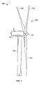
- a wind turbine 100 generally comprises a nacelle 102 housing a generator (not shown in FIG. 1 ).
- Nacelle 102 is a housing mounted atop a tower 104, only a portion of which is shown in FIG. 1 .
- the height of tower 104 is selected based upon factors and conditions known in the art, and may extend to heights up to 60 meters or more.
- the wind turbine 100 may be installed on any terrain providing access to areas having desirable wind conditions. The terrain may vary greatly and may include, but is not limited to, mountainous terrain or offshore locations.
- Wind turbine 100 also comprises a rotor 106 that includes one or more rotor blades 108 attached to a rotating hub 110. Although wind turbine 100 illustrated in FIG. 1 includes three rotor blades 108, there are no specific limits on the number of rotor blades 108 required by the present disclosure.
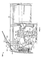
- a variable blade pitch drive 114 may control the pitch of blades 108 (not shown in FIG. 2 ) that drive hub 110 as a result of wind.
- Hub 110 may be configured to receive three blades 108, but other configurations may utilize any number of blades.
- the pitches of blades 108 are individually controlled by blade pitch drive 114.
- Hub 110 and blades 108 together comprise wind turbine rotor 106.
- the drive train of the wind turbine 100 includes a main rotor shaft 116 (also referred to as a "low speed shaft") connected to hub 110 via main bearing 130 and (in some configurations), at an opposite end of shaft 116 to a gear box 118.
- Gear box 118 in some configurations, utilizes a dual path geometry to drive an enclosed high-speed shaft.
- main rotor shaft 116 is coupled directly to generator 120.
- the high-speed shaft (not shown in FIG. 2 ) is used to drive generator 120, which is mounted on mainframe 132.
- rotor torque is transmitted via coupling 122.
- Generator 120 may be of any suitable type, for example and without limitation, a wound rotor induction generator or a direct drive permanent magnet generator.
- Yaw drive 124 and yaw deck 126 provide a yaw orientation system for wind turbine 100 to rotate the wind turbine to a position that faces the wind.
- Meteorological boom 128 provides information for a turbine control system, including wind direction and/or wind speed.
- the yaw system is mounted on a flange provided atop tower 104.
- the individual components within nacelle 102 may require servicing and/or replacement from time to time, either as a part of a regular maintenance schedule or due to malfunction or damage.
- the present disclosure includes installing a crane assembly 300 extending through hatch 331 to install/remove and lower/raise components from the ground to the wind turbine 100.
- FIG. 3 shows a cutaway view of a wind turbine 100 with a first crane assembly 300 according to an embodiment of the present disclosure installed.
- the first crane assembly 300 includes a first primary support member 301 and a second primary support member 303 rotatably attached to each other.
- the first crane assembly 300 further includes a boom member 304 pivotably attached to the second primary support member 303.
- the first primary support member 301 and the second primary support member 301 are attached such that the second primary support member 303 is permitted to coaxially rotate with respect to the first primary support member 301.
- the rotation may be facilitated by any suitable junction 302, including, but not limited to frictional interfaces, bearing arrangements or other structures that permit rotation.
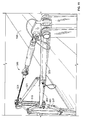
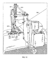
- the first crane assembly 300 extends though hatch 331 and provides lifting of components to/from other hatches 331 in the nacelle 102.
- the first primary support member 301 is attached to the wind turbine by attachment plate 311.
- Attachment plate 311 is configured to mate, attach or otherwise fasten to a component of the wind turbine 100. While not so limited, the attachment plate 311 may attach to or replace existing components, and utilize existing fastening locations. In one embodiment, the attachment plate 311 may be attached to existing footplates of main bearing 130.
- the first and second primary support members 301, 303 are additionally supported by secondary support members 307.
- the secondary support members 307 may be a bar, wire, cable, rope, chain, strap or any other elongated device capable of supporting the first and second primary support members 301, 303.
- Secondary support members 307 are affixed to the first primary support member 301 by collar 309. Collar 309 attaches to first primary support member 301 and support member 307 in any suitable manner and provides support.
- the support member 307 attaches to wind turbine 100 by secondary support fasteners 313 and secondary support clamps 315. While not so limited, the secondary support fasteners 313 may fasten to existing lifting eyes 513 (see e.g. FIG. 5 ) of the wind turbine 100.
- secondary support clamps 315 may be clamped or otherwise fastened to lips, features or surfaces within the wind turbine 100 that provide a desired angle providing support for the first and second primary support members 301, 303.
- the secondary support members 307 are preferably configured at an angle and connected to the first and second primary support members 301, 303 such that sufficient support is provided that wind turbine components of significant weight may be lifted by the lift member 305.
- the secondary support members 307 are configured to provide sufficient support for first and second primary support members 301, 303 to lift components from wind turbine 100 to and/or from the surface.
- Boom member 304 is pivotably attached to an end of the second primary support member 303.
- a boom actuator 317 is attached to second primary support member 303 and boom member 304.
- Boom actuator 317 may include a hydraulic drive or piston, electrically driven actuator or other device capable of pivoting boom member 304 to desired angles with respect to the first and second primary support members 301, 303.
- the boom actuator 317 is attached to boom member 304 by boom support 319.
- the disclosure is not so limited and may include other arrangements, including direct attachment of the boom actuator 317 to the boom member 304.
- Boom member 304 is additionally support by secondary boom supports 321.
- the secondary boom supports 321 may be a bar, wire, cable, rope, chain, strap or any other elongated device capable of supporting the boom member 304.
- Boom member extension 323 extends from boom member 304 and provides additional length for lifting. Like boom member 304, the boom member extension 323 is support by secondary boom supports 321.
- the boom member extension 323 may be actuatable by any suitable method, including by electric or hydraulic drives or by hand. In one embodiment, the boom member extension 323 may be actuated by hand and retained in position by a pin or other fastener.
- a lift member 305 is disposed at an end of boom member 304.
- the lift member 305 may include a winch, lift, chain drive or any other lifting mechanism that is capable of being supported by boom member 304 and lifting wind turbine components.
- Line 306 extends from lift member 305 and is attachable to turbine components that require lifting.
- Line 306 may be a wire, cable, rope, chain or any other elongated device for lifting.
- the lift member 305 provides a length of line 306 sufficiently long to lower wind turbine components to the ground from above hub 110 of the wind turbine 100.
- the position of lift member 305 is not limited to the end of boom member 304 and may be disposed in any location that permits lifting of components.
- lift member 305 may be mounted on second primary support member 303 and line 306 may be guided by pulleys or other structures to the end of boom member 304.
- the lift member 305 may utilize auxiliary components, such as spring loaded coiling drums or similar devices for line management and deployment.
- First crane assembly 300 provides 360° rotation about the axis passing through the first and second primary support members 301, 303.
- FIG. 5 shows a wind turbine servicing system 500 having a first crane assembly 300 and a second crane assembly 501 according to an embodiment of the present disclosure wherein the components within the nacelle 102 have been removed.
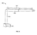
- the second crane assembly 501 includes a post member 503 and extendable swing member 505.
- the extendable swing member 505 being extendable via a telescoping cylinder or similar structure that permits extension of the swing member 505.
- the second crane assembly 501 includes a swing member actuator 507 which may drive the extendable swing member 505 in any suitable manner, including hydraulic or electric drive.
- the swing member 505 is rotatably attached to the post member 503 and allows the swing member 505 to lift, manipulate and move components within the nacelle 102.
- the second crane assembly 501 is capable of 360° rotation, allowing swing member 505 to lift and swing a load through a full circular path.
- the swing member 505 may be operated to provide components to and/or from the primary crane assembly 300.
- the second crane assembly 500 includes an attachment member 509 (see FIG. 8 and 9 ).
- the attachment member 509 is configured to clamp, engage, interlock or otherwise attach to a component within the nacelle 102.
- the second crane assembly 501 is clamped to torque arms 511.
- the present disclosure is not so limited and the second crane assembly 501 may be attached in any suitable location within the nacelle 102 to transfer and position components within the nacelle 102.
- FIGs. 11-13 show a first crane assembly 300 in an installed position, wherein the first crane assembly 300 extends through a hatch 331.
- hatches 331 may include a main hatch near the hub 110, through which the primary crane assembly 300 extends and side hatches along top edges of the nacelle 102.
- the present disclosure may be utilized with any configuration of hatches 331 that permit the first crane assembly 300 to extend therethrough and to which hatches 331 may access individual components for lifting.
- the wind turbine servicing system 500 according to the present disclosure permits installation and/or removal of a variety of components.
- the first crane assembly 300 may lift and install/remove components such as, but not limited to, blade pitch drives 114, yaw drives 124, pitch batteries, brake disks, high speed shaft couplings, oil coolers, oil filters, oil pumps, generator components, such as the generator commutator, or brush holder assembly, gearbox bearings, generator bearings, controller components, cables, and large and/or heavy service tools, such as ladders.
- the first crane assembly 300 may lift and install/remove components such as, but not limited to, complete generator coolers, complete generator assemblies, and gearbox housings.
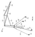
- FIG. 14 shows a first crane assembly 300 in an unassembled configuration.
- the individual components of the first crane assembly 300 and the second crane assembly 501 preferably do not exceed about 30kg and are sufficiently lightweight and sufficiently small to be handled manually. More specifically, the components of the first crane assembly 300 and second crane assembly 501 would be sufficiently disassemblable to permit the individual components to be carried by hand.
Landscapes
- Engineering & Computer Science (AREA)
- Mechanical Engineering (AREA)
- Life Sciences & Earth Sciences (AREA)
- Sustainable Development (AREA)
- Sustainable Energy (AREA)
- Chemical & Material Sciences (AREA)
- Combustion & Propulsion (AREA)
- General Engineering & Computer Science (AREA)
- Civil Engineering (AREA)
- Structural Engineering (AREA)
- Wind Motors (AREA)
Claims (2)
- Système d'entretien d'éolienne comprenant un assemblage de grue portable (300) pour entretenir une éolienne (100), comprenant :un premier élément support primaire (301) et un second élément support primaire (303) fixés l'un à l'autre de manière rotative, le premier élément support primaire (301) étant configuré pour être fixé à une plaque de fixation (311), la plaque de fixation étant configurée pour être fixée à un composant d'éolienne (100) et le second élément support primaire (303) pouvant tourner de manière coaxiale sur 360° par rapport au premier élément support primaire (301) ;caractérisé parune pluralité d'éléments supports secondaires (307) configurés pour être fixés au premier élément support primaire par un collier (309), dans lequel les éléments supports secondaires sont configurés pour supporter les premier et second éléments supports primaires (301, 303), les éléments supports secondaires (307) étant fixés à l'éolienne par une pluralité de montures de supports secondaires (313, 315) ;un élément de poutre (304) fixé de manière pivotante à une extrémité du second élément support primaire (303) ;une pluralité de supports de poutre secondaires (321) configurés pour être fixé à l'élément de poutre (304), les supports de poutre secondaires étant adaptés à supporter l'élément de poutre ; etun dispositif d'actionnement de poutre (317) fixé au second élément support primaire (303) et à l'élément de poutre (304), le dispositif d'actionnement de poutre étant capable de faire pivoter d'un certain angle l'élément de poutre par rapport aux premier et second éléments supports primaires (301, 303) ;dans lequel l'assemblage de grue portable (300) est démontable en composants de moins de 30 kg environ et peut être transporté manuellement.
- Système d'entretien d'éolienne selon la revendication 1, comprenant en outre :un second assemblage de grue (501) démontable en composants de moins de 30 kg environ et pouvant être transportés manuellement ;le second assemblage de grue (501) étant agencé et disposé de manière à permettre la manipulation des composants à l'intérieur de l'éolienne (100).
Applications Claiming Priority (2)
| Application Number | Priority Date | Filing Date | Title |
|---|---|---|---|
| US8348508P | 2008-07-24 | 2008-07-24 | |
| US12/256,499 US8104631B2 (en) | 2008-07-24 | 2008-10-23 | Portable crane system for wind turbine components |
Publications (2)
| Publication Number | Publication Date |
|---|---|
| EP2147885A1 EP2147885A1 (fr) | 2010-01-27 |
| EP2147885B1 true EP2147885B1 (fr) | 2013-02-27 |
Family
ID=41259800
Family Applications (1)
| Application Number | Title | Priority Date | Filing Date |
|---|---|---|---|
| EP09165826A Not-in-force EP2147885B1 (fr) | 2008-07-24 | 2009-07-17 | Système de grue portable pour composants d'éolienne |
Country Status (5)
| Country | Link |
|---|---|
| US (1) | US8104631B2 (fr) |
| EP (1) | EP2147885B1 (fr) |
| CN (1) | CN101654211B (fr) |
| DK (1) | DK2147885T3 (fr) |
| ES (1) | ES2402066T3 (fr) |
Cited By (2)
| Publication number | Priority date | Publication date | Assignee | Title |
|---|---|---|---|---|
| US9428369B2 (en) | 2013-09-11 | 2016-08-30 | General Electric Company | Articulated slewing jib crane and wind turbine incorporating same |
| US12473179B2 (en) | 2021-05-03 | 2025-11-18 | Liftra Ip Aps | Base for supporting a portable crane and a method for removing a main bearing of a wind turbine |
Families Citing this family (59)
| Publication number | Priority date | Publication date | Assignee | Title |
|---|---|---|---|---|
| KR101038641B1 (ko) * | 2008-09-01 | 2011-06-03 | 두산중공업 주식회사 | 풍력터빈설비의 유지 보수 시스템 |
| EP2189575B1 (fr) * | 2008-11-19 | 2021-06-30 | DEME Offshore BE N.V. | Offshore plate-forme auto-élévatrice et procédé |
| JP5650210B2 (ja) * | 2009-07-10 | 2015-01-07 | シーメンス アクチエンゲゼルシヤフトSiemens Aktiengesellschaft | 風力タービン主軸受け |
| ES2388822B1 (es) * | 2010-02-02 | 2013-09-06 | Matis Hispania S A | Dispositivo para la sustitucion del cilindro de inclinacion en el buje de un aerogenerador. |
| CN102216610B (zh) * | 2010-02-10 | 2014-08-20 | 三菱重工业株式会社 | 修理风力涡轮发电机的轴承的方法 |
| ES2559211T3 (es) * | 2010-07-13 | 2016-02-11 | Siemens Aktiengesellschaft | Plataforma de ensamblaje para el ensamblaje de una torre de turbina eólica o secciones de torre de turbina eólica |
| US9709038B2 (en) | 2010-12-15 | 2017-07-18 | Vestas Wind Systems A/S | Tool and a method for moving a wind turbine drivetrain component |
| GB2487230B (en) * | 2011-01-17 | 2015-09-23 | Granada Material Handling Ltd | Crane and crane assembly |
| WO2012105971A1 (fr) * | 2011-02-02 | 2012-08-09 | Smith Matthew K | Système de maintenance monté sur nacelle, pour éoliennes |
| US8807923B2 (en) * | 2011-02-07 | 2014-08-19 | Vestas Wind Systems A/S | Access apparatus for a wind turbine and method of using same |
| CN103348132B (zh) * | 2011-02-07 | 2016-02-17 | 菱重维斯塔斯海上风力有限公司 | 具有直升机平台装置的风轮机及其使用方法 |
| WO2012130243A2 (fr) * | 2011-03-30 | 2012-10-04 | Vestas Wind Systems A/S | Structure de nacelle pour une éolienne |
| DK2520533T4 (da) | 2011-05-05 | 2019-09-09 | Siemens Ag | Servicekran til en vindmølle |
| CN102180413B (zh) * | 2011-05-20 | 2012-12-05 | 中联重科股份有限公司 | 起重臂架系统及包含该起重臂架系统的起重设备 |
| DE102011077402A1 (de) * | 2011-06-10 | 2012-12-13 | Repower Systems Se | Rotorblatt einer Windenergieanlage und Windenergieanlage |
| EP2726394B1 (fr) * | 2011-06-28 | 2015-12-09 | Vestas Wind Systems A/S | Outil de levage pour l'entretien de composants d'un multiplicateur d'éolienne et procédé d'entretien utilisant un tel outil |
| US9278236B1 (en) | 2011-07-20 | 2016-03-08 | Flaresun Fire Group, Inc. | Victim retrieval system, method and apparatus |
| CN103101848A (zh) * | 2011-11-15 | 2013-05-15 | 浙江虎霸建设机械有限公司 | 塔式起重机便携式维修悬臂吊 |
| JP5281723B1 (ja) | 2011-11-30 | 2013-09-04 | 三菱重工業株式会社 | 再生エネルギー型発電装置およびその油漏れ検出方法 |
| JP5819785B2 (ja) * | 2012-06-21 | 2015-11-24 | 株式会社日立製作所 | 軸受交換のための分解装置 |
| JP5714178B2 (ja) * | 2012-07-31 | 2015-05-07 | 三菱重工業株式会社 | クレーン装置 |
| US9651020B2 (en) * | 2013-09-24 | 2017-05-16 | General Electric Company | Portable crane for use in wind turbines |
| EP3052802B1 (fr) | 2013-10-04 | 2020-01-08 | Inventus Holdings, LLC | Remplacement d'un composant d'éolienne en haut de tour |
| ES2644845T3 (es) * | 2013-11-27 | 2017-11-30 | Vestas Wind Systems A/S | Una góndola para un generador de turbina eólica que incluye un aparato de elevación |
| ES2540790B1 (es) * | 2014-01-11 | 2016-04-20 | Cástor CASAS TOJO | Sistema de grúas autoescalables y autoajustables para aerogeneradores |
| ES2755947T3 (es) * | 2014-03-31 | 2020-04-24 | Vestas Wind Sys As | Estructura de góndola de turbina eólica |
| DK201500527A1 (da) | 2014-10-07 | 2016-04-18 | Liftra Ip Aps | Hovedakselfixstur til fiksering af hovedakslen på en vindmølle ved gennemførelse af montage- og reparationsarbejder. |
| CN105129629B (zh) * | 2015-08-03 | 2017-06-23 | 北京金风科创风电设备有限公司 | 大部件提升系统及其拆卸方法、大部件提升方法 |
| DK3139058T3 (en) * | 2015-09-04 | 2018-04-23 | Sb Patent Holding Aps | Service system and method for servicing a brake device for a braking system with a horizontally positioned brake disc |
| US20180283359A1 (en) * | 2015-10-09 | 2018-10-04 | Windcare India Pvt Ltd | A system and method for raising and lowering a component of a wind turbine |
| EP3504149B1 (fr) * | 2016-08-29 | 2020-10-07 | MHI Vestas Offshore Wind A/S | Procédé et appareil de réalisation d'opérations de maintenance sur un élément d'éolienne |
| CN109790826A (zh) * | 2016-09-21 | 2019-05-21 | 维斯塔斯风力系统有限公司 | 用于打开风轮机的盖部分的方法 |
| ES2665004B1 (es) * | 2016-10-24 | 2019-01-29 | Gamesa Innovation & Technology S L | Grua de una turbina eólica |
| CN106401877A (zh) * | 2016-12-07 | 2017-02-15 | 浙江运达风电股份有限公司 | 一种用于拆装兆瓦级风电机组偏航制动器的专用装置 |
| CN108661864B (zh) * | 2017-03-29 | 2022-03-22 | 通用电气公司 | 用于风轮机的齿轮箱组件的修理方法 |
| ES2876008T3 (es) * | 2017-03-29 | 2021-11-11 | Gen Electric | Conjunto de grúa de buje para una turbina eólica |
| US10422322B2 (en) * | 2017-04-27 | 2019-09-24 | General Electric Company | System and method for removing or installing a main shaft of a wind turbine with main shaft support elements |
| US10352305B2 (en) * | 2017-04-27 | 2019-07-16 | General Electric Company | System and method for removing or installing a main shaft of a wind turbine with a push/pull system configured at an end of the main shaft |
| US10337503B2 (en) * | 2017-04-27 | 2019-07-02 | General Electric Company | System and method for removing or installing a main shaft of a wind turbine with rigging |
| CN107100800A (zh) * | 2017-05-11 | 2017-08-29 | 北京唐浩电力工程技术研究有限公司 | 一种用于风电机组机舱的便携式起重结构 |
| US10612527B2 (en) | 2017-06-13 | 2020-04-07 | General Electric Company | Methods for refurbishing wind turbines |
| EP3460272B1 (fr) * | 2017-09-20 | 2020-04-01 | Siemens Gamesa Renewable Energy A/S | Procédé pour changer un composant de palier et dispositif outil permettant de changer un composant de palier |
| CA3012945C (fr) * | 2017-11-22 | 2019-05-21 | LiftWerx Holdings Inc. | Systeme de levage installable dans une nacelle d'une eolienne |
| GB2569949A (en) * | 2017-12-29 | 2019-07-10 | Vestas Wind Sys As | Method of handling a wind turbine component and crane for same |
| BE1026068B9 (nl) * | 2018-07-26 | 2019-10-02 | Deme Offshore Holding N V | Inrichting en werkwijze voor het vanaf een steunvlak aan een uiteinde oprichten van een buisvormig element met een lengterichting |
| US10988351B2 (en) * | 2018-08-31 | 2021-04-27 | LiftWerx Holdings Inc. | Nacelle-mounted lift system for wind turbine |
| PL3870850T3 (pl) | 2018-10-24 | 2024-03-04 | LiftWerx Holdings Inc. | System podnoszący do otwierania części wierzchniej gondoli |
| DK181351B1 (en) * | 2019-03-01 | 2023-08-23 | Liftra Ip Aps | Crane system for hoisting of wind turbine components and method for moving a burden |
| CN110356959B (zh) * | 2019-08-13 | 2024-11-08 | 中国船舶重工集团海装风电股份有限公司 | 一种风轮吊装工装 |
| CN110697589B (zh) * | 2019-10-17 | 2020-10-02 | 济南一建集团有限公司 | 一种装配式建筑智能吊装设备 |
| EP4048887A1 (fr) * | 2019-10-22 | 2022-08-31 | LiftWerx Holdings Inc. | Système de levage pour une pale de rotor d'une éolienne |
| CN115053064B (zh) * | 2020-02-17 | 2025-08-08 | 维斯塔斯风力系统有限公司 | 用于风力涡轮机的机舱及制造风力涡轮机的方法 |
| WO2021168549A1 (fr) * | 2020-02-28 | 2021-09-02 | LiftWerx Holdings Inc. | Appareils de levage à tour montante multiples sur des éoliennes |
| EP4146932B1 (fr) * | 2020-05-07 | 2024-06-19 | Vestas Wind Systems A/S | Nacelle avec une grue permettant l'assemblage de la nacelle et procédé de fabrication de la nacelle |
| CN111847269A (zh) * | 2020-08-14 | 2020-10-30 | 南京高速齿轮制造有限公司 | 一种起吊工装 |
| CN113526368B (zh) * | 2021-05-25 | 2024-03-29 | 江苏金盛建设集团有限公司 | 一种建筑高空施工用有辅助固定功能的材料提料吊机 |
| NO348348B1 (en) * | 2021-06-11 | 2024-12-02 | Seaonics As | A crane for a ship |
| US12435699B1 (en) * | 2022-11-22 | 2025-10-07 | The Aes Corporation | Pitch motor trolley |
| WO2024223712A1 (fr) * | 2023-04-24 | 2024-10-31 | Liftra Ip Aps | Grue montée sur éolienne |
Family Cites Families (21)
| Publication number | Priority date | Publication date | Assignee | Title |
|---|---|---|---|---|
| US4112863A (en) * | 1977-08-31 | 1978-09-12 | Nelson Christian E | Barge-supported crane with hydraulically actuated ram corner lift means |
| US4700851A (en) * | 1985-04-18 | 1987-10-20 | Reeve Richard J | Lightweight, self-powered, transportable crane assembly |
| US5211526A (en) * | 1992-02-28 | 1993-05-18 | Larry Robinette | Mobile crane |
| DE60014071T2 (de) * | 1999-02-24 | 2005-11-24 | Marine Current Turbines Ltd. | Um eine hülse angeordnete wasserströmungsturbine |
| US6095349A (en) | 1999-06-08 | 2000-08-01 | Orm Consulting, Inc. | Knock-down hoist |
| ES2228121T3 (es) | 1999-11-03 | 2005-04-01 | Vestas Wind Systems A/S | Procedimiento de control de la operacion de una turbina electrica y turbina electrica para usarse en dicho procedimiento. |
| DE19955516C1 (de) * | 1999-11-18 | 2001-12-20 | Tacke Windenergie Gmbh | Windkraftanlage und Verfahren zum Aus- und Einbau der Hauptkomponenten des Maschinengehäuses einer Windkraftanlage |
| NL1014553C2 (nl) | 2000-03-03 | 2001-09-04 | Lagerwey Windturbine B V | Hijsinrichting en werkwijze voor samenbouwen van een windmolen, alsmede een windmolen. |
| EP1266138A1 (fr) | 2000-03-08 | 2002-12-18 | Forskningscenter Riso | Procede d'utilisation d'une turbine |
| FR2808252B1 (fr) * | 2000-04-26 | 2004-05-28 | France Etat | Navire porte conteneur autonome |
| ATE366226T1 (de) * | 2000-10-25 | 2007-07-15 | Nordex Energy Gmbh | Verfahren zum anbringen eines kranes an einer windmühle |
| DE10109553B4 (de) | 2001-02-28 | 2006-03-30 | Wobben, Aloys, Dipl.-Ing. | Luftdichteabhängige Leistungsregelung |
| DE10127451C5 (de) | 2001-06-07 | 2016-09-01 | Aloys Wobben | Verfahren zur Steuerung einer Windenergieanlage |
| EP1291521A1 (fr) * | 2001-09-06 | 2003-03-12 | Turbowinds N.V./S.A. | Eolienne avec grue de bord mobile |
| ES2423430T3 (es) * | 2003-09-26 | 2013-09-20 | Vestas Wind Systems A/S | Equipo para ser montado en el buje de una turbina eólica y procedimiento para realizar el mantenimiento de una turbina eólica utilizando tal equipo |
| JP4343713B2 (ja) * | 2004-01-15 | 2009-10-14 | 株式会社巴技研 | 風力発電機の構築装置及び風力発電機の構築方法。 |
| US7156246B2 (en) * | 2004-09-15 | 2007-01-02 | Sherrod Gregory F | Retractable rotating ATV mounted lift boom |
| ES2316200B1 (es) * | 2004-12-21 | 2010-01-11 | GAMESA INNOVATION & TECHNOLOGY, S.L. | Aerogenerador con grua desmontable y pescante auxiliar y procedimiento de montaje de dicha grua. |
| US8649911B2 (en) | 2005-06-03 | 2014-02-11 | General Electric Company | System and method for operating a wind farm under high wind speed conditions |
| US7476985B2 (en) | 2005-07-22 | 2009-01-13 | Gamesa Innovation & Technology, S.L. | Method of operating a wind turbine |
| WO2008069818A1 (fr) | 2006-12-08 | 2008-06-12 | General Electric Company | Grue à plate-forme mobile pour pièces d'éolienne |
-
2008
- 2008-10-23 US US12/256,499 patent/US8104631B2/en not_active Expired - Fee Related
-
2009
- 2009-07-17 ES ES09165826T patent/ES2402066T3/es active Active
- 2009-07-17 DK DK09165826.0T patent/DK2147885T3/da active
- 2009-07-17 EP EP09165826A patent/EP2147885B1/fr not_active Not-in-force
- 2009-07-24 CN CN200910164940.3A patent/CN101654211B/zh not_active Expired - Fee Related
Cited By (2)
| Publication number | Priority date | Publication date | Assignee | Title |
|---|---|---|---|---|
| US9428369B2 (en) | 2013-09-11 | 2016-08-30 | General Electric Company | Articulated slewing jib crane and wind turbine incorporating same |
| US12473179B2 (en) | 2021-05-03 | 2025-11-18 | Liftra Ip Aps | Base for supporting a portable crane and a method for removing a main bearing of a wind turbine |
Also Published As
| Publication number | Publication date |
|---|---|
| ES2402066T3 (es) | 2013-04-26 |
| EP2147885A1 (fr) | 2010-01-27 |
| US20100021278A1 (en) | 2010-01-28 |
| DK2147885T3 (da) | 2013-03-25 |
| CN101654211A (zh) | 2010-02-24 |
| US8104631B2 (en) | 2012-01-31 |
| CN101654211B (zh) | 2016-03-16 |
Similar Documents
| Publication | Publication Date | Title |
|---|---|---|
| EP2147885B1 (fr) | Système de grue portable pour composants d'éolienne | |
| CN101798993B (zh) | 用于风力涡轮机塔架的内部偏航驱动器置换 | |
| CN103403344B (zh) | 借助涡轮机轮毂的无起重机方式的风力涡轮机叶片操纵方法 | |
| AU2003211860B2 (en) | Wind energy turbine | |
| CA2928179C (fr) | Systeme et methode de remplacement d'un palier de pas | |
| EP2926000B1 (fr) | Procédé permettant de déplacer des composants d'éolienne et système de transport permettant de déplacer des composants d'éolienne | |
| WO2008069818A1 (fr) | Grue à plate-forme mobile pour pièces d'éolienne | |
| CN110902556B (zh) | 一种能调整风电叶片空中姿态的吊具及其叶片装拆方法 | |
| WO2010024510A1 (fr) | Système de maintenance pour un équipement d'éolienne | |
| WO2010115135A1 (fr) | Treuil pour l'entretien des éoliennes | |
| KR20160148682A (ko) | 풍력터빈 날개의 해체 및 조립 방법과 시스템 | |
| US20160090961A1 (en) | Installing blades in a wind turbine and wind turbine lifting systems | |
| EP3730783B1 (fr) | Système et procédé de réparation d'une boîte de vitesses installée dans une éolienne | |
| US12037979B2 (en) | Method for handling a wind turbine component and associated lifting system | |
| EP3631193B1 (fr) | Procédé de démontage d'une éolienne et de montage d'un système de production d'énergie éolienne aéroporté | |
| EP4457437B1 (fr) | Procédé d'assemblage d'une nacelle d'une éolienne et agencement de levage associé | |
| CN211971517U (zh) | 一种能调整风电叶片空中姿态的吊具 | |
| EP3364023B1 (fr) | Système et procédé pour retirer ou installer un arbre principal d'une éolienne | |
| EP4602264A1 (fr) | Procédé de manipulation d'une pale d'éolienne à l'aide d'un système de grue | |
| WO2022128029A1 (fr) | Système de liaison pour fixer un système d'accès à une pale à une nacelle d'une éolienne et son procédé d'utilisation |
Legal Events
| Date | Code | Title | Description |
|---|---|---|---|
| PUAI | Public reference made under article 153(3) epc to a published international application that has entered the european phase |
Free format text: ORIGINAL CODE: 0009012 |
|
| AK | Designated contracting states |
Kind code of ref document: A1 Designated state(s): AT BE BG CH CY CZ DE DK EE ES FI FR GB GR HR HU IE IS IT LI LT LU LV MC MK MT NL NO PL PT RO SE SI SK SM TR |
|
| 17P | Request for examination filed |
Effective date: 20100727 |
|
| 17Q | First examination report despatched |
Effective date: 20100910 |
|
| REG | Reference to a national code |
Ref country code: DE Ref legal event code: R079 Ref document number: 602009013592 Country of ref document: DE Free format text: PREVIOUS MAIN CLASS: B66C0023060000 Ipc: B66C0023200000 |
|
| RIC1 | Information provided on ipc code assigned before grant |
Ipc: F03D 11/04 20060101ALI20120807BHEP Ipc: B66C 23/06 20060101ALI20120807BHEP Ipc: B66C 23/20 20060101AFI20120807BHEP Ipc: F03D 1/00 20060101ALI20120807BHEP |
|
| GRAJ | Information related to disapproval of communication of intention to grant by the applicant or resumption of examination proceedings by the epo deleted |
Free format text: ORIGINAL CODE: EPIDOSDIGR1 |
|
| GRAP | Despatch of communication of intention to grant a patent |
Free format text: ORIGINAL CODE: EPIDOSNIGR1 |
|
| GRAP | Despatch of communication of intention to grant a patent |
Free format text: ORIGINAL CODE: EPIDOSNIGR1 |
|
| GRAS | Grant fee paid |
Free format text: ORIGINAL CODE: EPIDOSNIGR3 |
|
| GRAA | (expected) grant |
Free format text: ORIGINAL CODE: 0009210 |
|
| AK | Designated contracting states |
Kind code of ref document: B1 Designated state(s): AT BE BG CH CY CZ DE DK EE ES FI FR GB GR HR HU IE IS IT LI LT LU LV MC MK MT NL NO PL PT RO SE SI SK SM TR |
|
| REG | Reference to a national code |
Ref country code: GB Ref legal event code: FG4D |
|
| REG | Reference to a national code |
Ref country code: CH Ref legal event code: EP |
|
| REG | Reference to a national code |
Ref country code: AT Ref legal event code: REF Ref document number: 598392 Country of ref document: AT Kind code of ref document: T Effective date: 20130315 |
|
| REG | Reference to a national code |
Ref country code: DK Ref legal event code: T3 |
|
| REG | Reference to a national code |
Ref country code: IE Ref legal event code: FG4D |
|
| REG | Reference to a national code |
Ref country code: DE Ref legal event code: R096 Ref document number: 602009013592 Country of ref document: DE Effective date: 20130425 |
|
| REG | Reference to a national code |
Ref country code: AT Ref legal event code: MK05 Ref document number: 598392 Country of ref document: AT Kind code of ref document: T Effective date: 20130227 |
|
| REG | Reference to a national code |
Ref country code: LT Ref legal event code: MG4D |
|
| PG25 | Lapsed in a contracting state [announced via postgrant information from national office to epo] |
Ref country code: IS Free format text: LAPSE BECAUSE OF FAILURE TO SUBMIT A TRANSLATION OF THE DESCRIPTION OR TO PAY THE FEE WITHIN THE PRESCRIBED TIME-LIMIT Effective date: 20130627 Ref country code: AT Free format text: LAPSE BECAUSE OF FAILURE TO SUBMIT A TRANSLATION OF THE DESCRIPTION OR TO PAY THE FEE WITHIN THE PRESCRIBED TIME-LIMIT Effective date: 20130227 Ref country code: LT Free format text: LAPSE BECAUSE OF FAILURE TO SUBMIT A TRANSLATION OF THE DESCRIPTION OR TO PAY THE FEE WITHIN THE PRESCRIBED TIME-LIMIT Effective date: 20130227 Ref country code: NO Free format text: LAPSE BECAUSE OF FAILURE TO SUBMIT A TRANSLATION OF THE DESCRIPTION OR TO PAY THE FEE WITHIN THE PRESCRIBED TIME-LIMIT Effective date: 20130527 Ref country code: SE Free format text: LAPSE BECAUSE OF FAILURE TO SUBMIT A TRANSLATION OF THE DESCRIPTION OR TO PAY THE FEE WITHIN THE PRESCRIBED TIME-LIMIT Effective date: 20130227 Ref country code: BG Free format text: LAPSE BECAUSE OF FAILURE TO SUBMIT A TRANSLATION OF THE DESCRIPTION OR TO PAY THE FEE WITHIN THE PRESCRIBED TIME-LIMIT Effective date: 20130527 |
|
| REG | Reference to a national code |
Ref country code: NL Ref legal event code: VDEP Effective date: 20130227 |
|
| PG25 | Lapsed in a contracting state [announced via postgrant information from national office to epo] |
Ref country code: BE Free format text: LAPSE BECAUSE OF FAILURE TO SUBMIT A TRANSLATION OF THE DESCRIPTION OR TO PAY THE FEE WITHIN THE PRESCRIBED TIME-LIMIT Effective date: 20130227 Ref country code: PT Free format text: LAPSE BECAUSE OF FAILURE TO SUBMIT A TRANSLATION OF THE DESCRIPTION OR TO PAY THE FEE WITHIN THE PRESCRIBED TIME-LIMIT Effective date: 20130627 Ref country code: FI Free format text: LAPSE BECAUSE OF FAILURE TO SUBMIT A TRANSLATION OF THE DESCRIPTION OR TO PAY THE FEE WITHIN THE PRESCRIBED TIME-LIMIT Effective date: 20130227 Ref country code: SI Free format text: LAPSE BECAUSE OF FAILURE TO SUBMIT A TRANSLATION OF THE DESCRIPTION OR TO PAY THE FEE WITHIN THE PRESCRIBED TIME-LIMIT Effective date: 20130227 Ref country code: PL Free format text: LAPSE BECAUSE OF FAILURE TO SUBMIT A TRANSLATION OF THE DESCRIPTION OR TO PAY THE FEE WITHIN THE PRESCRIBED TIME-LIMIT Effective date: 20130227 Ref country code: LV Free format text: LAPSE BECAUSE OF FAILURE TO SUBMIT A TRANSLATION OF THE DESCRIPTION OR TO PAY THE FEE WITHIN THE PRESCRIBED TIME-LIMIT Effective date: 20130227 Ref country code: GR Free format text: LAPSE BECAUSE OF FAILURE TO SUBMIT A TRANSLATION OF THE DESCRIPTION OR TO PAY THE FEE WITHIN THE PRESCRIBED TIME-LIMIT Effective date: 20130528 |
|
| PG25 | Lapsed in a contracting state [announced via postgrant information from national office to epo] |
Ref country code: HR Free format text: LAPSE BECAUSE OF FAILURE TO SUBMIT A TRANSLATION OF THE DESCRIPTION OR TO PAY THE FEE WITHIN THE PRESCRIBED TIME-LIMIT Effective date: 20130227 |
|
| PG25 | Lapsed in a contracting state [announced via postgrant information from national office to epo] |
Ref country code: RO Free format text: LAPSE BECAUSE OF FAILURE TO SUBMIT A TRANSLATION OF THE DESCRIPTION OR TO PAY THE FEE WITHIN THE PRESCRIBED TIME-LIMIT Effective date: 20130227 Ref country code: EE Free format text: LAPSE BECAUSE OF FAILURE TO SUBMIT A TRANSLATION OF THE DESCRIPTION OR TO PAY THE FEE WITHIN THE PRESCRIBED TIME-LIMIT Effective date: 20130227 Ref country code: CZ Free format text: LAPSE BECAUSE OF FAILURE TO SUBMIT A TRANSLATION OF THE DESCRIPTION OR TO PAY THE FEE WITHIN THE PRESCRIBED TIME-LIMIT Effective date: 20130227 Ref country code: NL Free format text: LAPSE BECAUSE OF FAILURE TO SUBMIT A TRANSLATION OF THE DESCRIPTION OR TO PAY THE FEE WITHIN THE PRESCRIBED TIME-LIMIT Effective date: 20130227 Ref country code: SK Free format text: LAPSE BECAUSE OF FAILURE TO SUBMIT A TRANSLATION OF THE DESCRIPTION OR TO PAY THE FEE WITHIN THE PRESCRIBED TIME-LIMIT Effective date: 20130227 |
|
| PG25 | Lapsed in a contracting state [announced via postgrant information from national office to epo] |
Ref country code: CY Free format text: LAPSE BECAUSE OF FAILURE TO SUBMIT A TRANSLATION OF THE DESCRIPTION OR TO PAY THE FEE WITHIN THE PRESCRIBED TIME-LIMIT Effective date: 20130227 |
|
| PG25 | Lapsed in a contracting state [announced via postgrant information from national office to epo] |
Ref country code: IT Free format text: LAPSE BECAUSE OF FAILURE TO SUBMIT A TRANSLATION OF THE DESCRIPTION OR TO PAY THE FEE WITHIN THE PRESCRIBED TIME-LIMIT Effective date: 20130227 |
|
| PLBE | No opposition filed within time limit |
Free format text: ORIGINAL CODE: 0009261 |
|
| STAA | Information on the status of an ep patent application or granted ep patent |
Free format text: STATUS: NO OPPOSITION FILED WITHIN TIME LIMIT |
|
| 26N | No opposition filed |
Effective date: 20131128 |
|
| PG25 | Lapsed in a contracting state [announced via postgrant information from national office to epo] |
Ref country code: MC Free format text: LAPSE BECAUSE OF FAILURE TO SUBMIT A TRANSLATION OF THE DESCRIPTION OR TO PAY THE FEE WITHIN THE PRESCRIBED TIME-LIMIT Effective date: 20130227 |
|
| REG | Reference to a national code |
Ref country code: CH Ref legal event code: PL |
|
| REG | Reference to a national code |
Ref country code: DE Ref legal event code: R097 Ref document number: 602009013592 Country of ref document: DE Effective date: 20131128 |
|
| GBPC | Gb: european patent ceased through non-payment of renewal fee |
Effective date: 20130717 |
|
| REG | Reference to a national code |
Ref country code: IE Ref legal event code: MM4A |
|
| REG | Reference to a national code |
Ref country code: FR Ref legal event code: ST Effective date: 20140331 |
|
| PG25 | Lapsed in a contracting state [announced via postgrant information from national office to epo] |
Ref country code: GB Free format text: LAPSE BECAUSE OF NON-PAYMENT OF DUE FEES Effective date: 20130717 Ref country code: CH Free format text: LAPSE BECAUSE OF NON-PAYMENT OF DUE FEES Effective date: 20130731 Ref country code: LI Free format text: LAPSE BECAUSE OF NON-PAYMENT OF DUE FEES Effective date: 20130731 |
|
| PG25 | Lapsed in a contracting state [announced via postgrant information from national office to epo] |
Ref country code: FR Free format text: LAPSE BECAUSE OF NON-PAYMENT OF DUE FEES Effective date: 20130731 |
|
| PG25 | Lapsed in a contracting state [announced via postgrant information from national office to epo] |
Ref country code: IE Free format text: LAPSE BECAUSE OF NON-PAYMENT OF DUE FEES Effective date: 20130717 |
|
| PG25 | Lapsed in a contracting state [announced via postgrant information from national office to epo] |
Ref country code: SM Free format text: LAPSE BECAUSE OF FAILURE TO SUBMIT A TRANSLATION OF THE DESCRIPTION OR TO PAY THE FEE WITHIN THE PRESCRIBED TIME-LIMIT Effective date: 20130227 |
|
| PG25 | Lapsed in a contracting state [announced via postgrant information from national office to epo] |
Ref country code: TR Free format text: LAPSE BECAUSE OF FAILURE TO SUBMIT A TRANSLATION OF THE DESCRIPTION OR TO PAY THE FEE WITHIN THE PRESCRIBED TIME-LIMIT Effective date: 20130227 Ref country code: MT Free format text: LAPSE BECAUSE OF FAILURE TO SUBMIT A TRANSLATION OF THE DESCRIPTION OR TO PAY THE FEE WITHIN THE PRESCRIBED TIME-LIMIT Effective date: 20130227 |
|
| PG25 | Lapsed in a contracting state [announced via postgrant information from national office to epo] |
Ref country code: MK Free format text: LAPSE BECAUSE OF FAILURE TO SUBMIT A TRANSLATION OF THE DESCRIPTION OR TO PAY THE FEE WITHIN THE PRESCRIBED TIME-LIMIT Effective date: 20130227 Ref country code: HU Free format text: LAPSE BECAUSE OF FAILURE TO SUBMIT A TRANSLATION OF THE DESCRIPTION OR TO PAY THE FEE WITHIN THE PRESCRIBED TIME-LIMIT; INVALID AB INITIO Effective date: 20090717 Ref country code: LU Free format text: LAPSE BECAUSE OF NON-PAYMENT OF DUE FEES Effective date: 20130717 |
|
| PGFP | Annual fee paid to national office [announced via postgrant information from national office to epo] |
Ref country code: DE Payment date: 20180620 Year of fee payment: 10 Ref country code: ES Payment date: 20180801 Year of fee payment: 10 |
|
| PGFP | Annual fee paid to national office [announced via postgrant information from national office to epo] |
Ref country code: DK Payment date: 20180625 Year of fee payment: 10 |
|
| REG | Reference to a national code |
Ref country code: DE Ref legal event code: R119 Ref document number: 602009013592 Country of ref document: DE |
|
| REG | Reference to a national code |
Ref country code: DK Ref legal event code: EBP Effective date: 20190731 |
|
| PG25 | Lapsed in a contracting state [announced via postgrant information from national office to epo] |
Ref country code: DE Free format text: LAPSE BECAUSE OF NON-PAYMENT OF DUE FEES Effective date: 20200201 |
|
| PG25 | Lapsed in a contracting state [announced via postgrant information from national office to epo] |
Ref country code: DK Free format text: LAPSE BECAUSE OF NON-PAYMENT OF DUE FEES Effective date: 20190731 |
|
| REG | Reference to a national code |
Ref country code: ES Ref legal event code: FD2A Effective date: 20201130 |
|
| PG25 | Lapsed in a contracting state [announced via postgrant information from national office to epo] |
Ref country code: ES Free format text: LAPSE BECAUSE OF NON-PAYMENT OF DUE FEES Effective date: 20190718 |