EP2147993A1 - Nouages de chaînes à tisser dotés d'une reconnaissance des paramètres de fils - Google Patents
Nouages de chaînes à tisser dotés d'une reconnaissance des paramètres de fils Download PDFInfo
- Publication number
- EP2147993A1 EP2147993A1 EP08405187A EP08405187A EP2147993A1 EP 2147993 A1 EP2147993 A1 EP 2147993A1 EP 08405187 A EP08405187 A EP 08405187A EP 08405187 A EP08405187 A EP 08405187A EP 2147993 A1 EP2147993 A1 EP 2147993A1
- Authority
- EP
- European Patent Office
- Prior art keywords
- warp
- thread
- measuring device
- optical measuring
- separated
- Prior art date
- Legal status (The legal status is an assumption and is not a legal conclusion. Google has not performed a legal analysis and makes no representation as to the accuracy of the status listed.)
- Withdrawn
Links
- 230000003287 optical effect Effects 0.000 claims abstract description 82
- 238000000034 method Methods 0.000 claims abstract description 18
- 238000012545 processing Methods 0.000 claims abstract description 7
- 238000005304 joining Methods 0.000 claims abstract description 6
- 238000005520 cutting process Methods 0.000 claims description 2
- 238000000926 separation method Methods 0.000 abstract description 6
- 238000005259 measurement Methods 0.000 abstract description 2
- 230000000052 comparative effect Effects 0.000 abstract 1
- 230000026676 system process Effects 0.000 abstract 1
- 239000000463 material Substances 0.000 description 13
- 238000012360 testing method Methods 0.000 description 5
- 239000003086 colorant Substances 0.000 description 3
- 238000001514 detection method Methods 0.000 description 2
- 238000011156 evaluation Methods 0.000 description 2
- 238000004519 manufacturing process Methods 0.000 description 2
- 239000004753 textile Substances 0.000 description 2
- 206010020112 Hirsutism Diseases 0.000 description 1
- 238000004026 adhesive bonding Methods 0.000 description 1
- 230000005540 biological transmission Effects 0.000 description 1
- 238000012937 correction Methods 0.000 description 1
- 239000004744 fabric Substances 0.000 description 1
- 239000000835 fiber Substances 0.000 description 1
- 238000012544 monitoring process Methods 0.000 description 1
- 238000000275 quality assurance Methods 0.000 description 1
- 230000033458 reproduction Effects 0.000 description 1
- 238000009941 weaving Methods 0.000 description 1
- 238000003466 welding Methods 0.000 description 1
Images



Classifications
-
- D—TEXTILES; PAPER
- D03—WEAVING
- D03J—AUXILIARY WEAVING APPARATUS; WEAVERS' TOOLS; SHUTTLES
- D03J1/00—Auxiliary apparatus combined with or associated with looms
- D03J1/16—Apparatus for joining warp ends
- D03J1/18—Apparatus for joining warp ends for joining, e.g. tying, a complete series of fresh warp threads to the used warp threads
Definitions
- the invention relates to a device for connecting warp threads comprising a first separating device for separating a warp thread from a first warp, a second separating device for separating a warp thread from a second warp and a connecting device for connecting the separated from the first warp warp with the the second warp separated warp, preferably at the ends. Furthermore, the invention discloses a method for joining warp threads.
- threads are often connected by linking.
- the threads are on so-called warps, each consisting of at least one layer with several side by side arranged warp threads.
- a warp thread of the expired warp is connected to a warp thread of the new warp.
- this connection always takes place between two corresponding warp threads.
- the first warp of the old warp with the first warp of the new warp and the second warp of the old with the second warp of the new warp etc. is linked together. This thread arrangement is desirable for achieving a straight thread course without crossings in the weaving machine.
- the order of warp threads with different threads within a warp is determined by the color repeat and the order of different yarns within a warp through the material repeat.
- the thread order is ensured by the fact that the warp threads of a thread layer are counted exactly and are distributed at the right place on the warp width. In multi-colored warp threads with different yarns also a crosshair is inserted to secure the thread order.
- This object is achieved by a device of the type mentioned above, which additionally has at least one optical measuring device for determining a yarn parameter of the warp thread separated from the first or second warp. Furthermore, the object is achieved by a method according to claim 16.
- the knotted warp has a high quality because it prevents bad linking of old and new warp threads. Furthermore, the knotting process can be tracked in real time by means of the optical measuring device and it can be manufactured at a higher speed, since no more control stops are required. The presence of an operator in production for quality assurance is no longer necessary.
- the device may have a second optical measuring device for determining at least one yarn parameter of the warp separated from a warp, wherein the first optical measuring device at least one yarn parameter of a warp from the first warp and the second optical measuring device at least one yarn parameter of a warp captured from the second warp.
- the detection process of the yarn parameters is thus improved.
- the device may comprise at least one control device which controls at least the first and the second separating device and the connecting device.
- the device can have at least one device for carrying out a desired-actual-value comparison of yarn parameters.
- predetermined or known yarn parameters can be compared with the determined values, so that an evaluation of the respective warp thread is possible.
- the first and the second separating device and the connecting device are controllable in dependence on a result of this desired-actual-value comparison.
- the device can respond to different measurement results react and, if necessary, return a wrong warp thread to the warp. If two correct warp threads have been separated, a connection can be made with the connecting device.
- the first and / or the second optical measuring device comprises at least one optical system for producing an image of the separated warp thread and at least one image processing system for processing the image, wherein the respective measured values or yarn parameters can be determined with the aid of the image processing system.
- a generated image is z.
- B. optically detect the color of a warp, so that different warp threads according to the proposed Kettfadenrapport (color repeat and / or material repeat) can be linked together. Furthermore, by the determined image of the warp thread whose diameter is optically determinable.
- the first and / or the second optical measuring device can preferably have a first and a second optical system for producing an image of the separated warp thread.
- a first and a second optical system for producing an image of the separated warp thread.
- the first and the second optical system of the first and / or the second optical measuring device each having an optical axis, which intersect spatially and form a cutting angle.
- intersection angle of the optical axes of the first and the second optical system of the first and / or the second optical measuring device has values in the range of 0-180 °, preferably assumes the value 45 °. If the angle of intersection is within this range, very accurate readings can be obtained and it has been shown that at 45 °, the image of the thread is most clearly visible.
- the first optical measuring device can be arranged above the first warp, so that a thread separated from this warp can be brought to the first optical measuring device by the first separating device.
- the intersection of the two optical axes of the first and second optical system of the first and / or second optical measuring device may be spaced from the first and / or second warp.
- the warps can be performed in addition to the device according to the invention, so that a precise separation can be done by means of the separation of the warp threads.
- the second optical measuring device can be arranged below the second warp, so that after the second separating device has separated a thread, the second optical measuring device detects this well metrologically.
- the first and second separating means may be horizontally movable to separate a warp thread from a warp.
- the Separierzi is characterized precisely controlled and it can be used a linear guide.
- the first and / or the second optical measuring device to the respective warp be movable, preferably horizontally movable.
- first and / or the second optical measuring device can preferably be movable together with the first and / or second separating device.
- the first and the second warp can be arranged opposite one another and preferably one above the other. By this arrangement, an optimal arrangement of the two warp is guaranteed during the process.
- the device according to the invention can be used for example in a textile machine, in particular in a knotting machine for separating threads.
- a textile machine in particular in a knotting machine for separating threads.
- the following methods can be used to join the individual warp threads: linking, wrapping, gluing, splicing or welding.
- the method according to the invention for joining warp threads of a first warp with warp threads of a second warp comprises the following steps: separating a warp thread from the first warp, separating a warp thread from the second warp and determining at least one yarn parameter of the warp separated from the first or second warp by means of at least one optical measuring device.
- Fig. 1 shows a separating system with an optical measuring device 7, which has a first optical system 11 and a second optical system 12.
- a semicolon line shows one optical axis for each optical system.
- a cone of the image capture is schematically drawn, which represents the detection range of the optical system.
- Below the optical measuring device 7 runs in the transverse direction, a first warp 2 or a second warp 3, wherein the respective warp consists of a layer of sibling strands. Shown are further two longitudinal beams, the z. B. can serve as support elements of the device.
- the reference numeral 4 represents a separating device with which a warp thread can be separated from the warp 2 and is movable relative to the optical measuring device 7. It is also conceivable for a relative movement of the optical system 11 or 12 to the separating device 4 to take place after the separation of a warp thread.
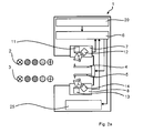
- Fig. 2a is a schematic representation of a device 1 according to the invention shown in the starting position.
- two warps 2 and 3 are arranged on the left side adjacent thereto, the direction of the longitudinal extent the threads perpendicular to the plane in the Fig. 2a runs.
- thread layer can also be used, so that the reference numeral 2 shows an upper thread layer 2 and the reference numeral 3 shows a lower thread layer 2.
- the two thread layers are arranged in parallel over each other and each thread layer may consist of different warp threads.
- warp threads of the respective thread layer 2 or 3 differ in their colors and the respective colors are arranged in a predetermined order within the thread layer, so below is a specification of the arrangement (order) of the respective colors within the thread layer as "Farbrapport" of respective thread layer (warp) referred to.
- warp threads of the respective thread layer 2 or 3 consist of different materials and the respective materials are arranged in a predetermined order within the thread layer, then a specification of the arrangement (order) of the respective materials within the thread layer as a "material repeat" of the respective Thread layer (warp) called.
- Each thread layer contains different warp threads, but identical warp threads are arranged opposite one another, so that their sequence is identical in a separation.
- a predetermined warp thread of the upper thread layer is to be linked to a predetermined warp thread of the lower thread layer in each case.
- the programming 20, a controller 6 and a feed device 25 for moving or positioning the device 1 with respect to the thread layer 2 and the thread layer 3rd contains. Arrows symbolize the individual data streams between the machine elements.
- a first separating device 4 and a second separating device 5 are shown, which are in a starting position. Above the first separating device 4 is a first optical measuring device 7, which in this embodiment has a first and a second optical system 11 and 12.
- a second optical measuring device 8 is arranged, which has the same structure as the measuring device 7 and therefore also includes two optical systems.
- the second optical measuring device 8 is located below the second separating device 5, so that a separated warp thread of this second optical measuring device can be fed. In the starting position shown here, the machine starts to move to the left against the warp, the optical measuring devices looking for the beginning of the thread layers.
- the first separating means 4 is near a first warp thread of the upper thread layer and the second separating means 5 is near a first warp thread of the lower thread layer, and the two optical measuring means 7 and 8 respectively recognize this first thread.
- the machine moves horizontally to the thread layers, it is also conceivable that the warp chains are moved to the machine or this feeding movement of the machine and the warps as it were to each other.
- the Fig. 2c represents the point in time where the first separating device 4 and the second separating device 5 each have separated a thread and brings it into a test position, so that the optical measuring devices the yarn parameters can measure and capture.
- the first separating device 4 can thereby move relative to the first optical measuring device 7, or the first optical measuring device 7 moves toward the separated warp thread.
- the Fig. 3 shows different examples of Farbrapporten, wherein in Example 1 same color repeats and in Example 2 different color reproductions are shown.
- the following is a flow principle for linking warp threads will be described.
- the two warps are clamped on a knotting frame, so that the two warp chains are opposite each other.
- the color repeat and / or the material repeat of the upper and lower thread layers is stored in the knotting machine, the respective repeat defining the number and type of warp threads in the upper and lower warp thread layers.
- the programming of the color repeat and / or the material repeat is carried out either directly on the knotting machine or by means of a suitable program, on a remote PC, from where the respective repeat is transmitted by data transmission or data carrier to the knotting machine. Subsequently, the knotting machine is placed on the knotting frame, loaded the respective repeat of the thread layer to be knotted and started the machine. Thus, the machine moves in the direction of the thread layer, and as soon as the beginning of a thread layer is detected, the machine searches for the beginning of the second thread layer and pushes them until the two thread layer starts are approximately perpendicular to each other.
- the separating devices of the knotting machine separate the respective foremost warp thread from a thread layer and bring it into a test position.
- the optical measuring devices can detect whether the respectively separated warp thread is a monofilament or a double thread is. If there is a suspicion of a double thread, the machine stops and the operator is asked to correct the error. It is also conceivable that the machine does not stop immediately, but independently tries to repeat the Separiervorgang until the right warp thread has been separated. The number of repetitions may not exceed a given value. If ever a single warp thread is in the test position, the optical measuring devices measure its yarn parameters.
- the yarn parameters include optical characteristics such as titer (diameter, volume, cross section), color, rotation (yes / no, touring, left / right), hairiness, spun yarn (staple length, fiber fineness) or filament yarn (monofilament, multi filament, number of fibrils, turned / untwisted, cross-section of the fibrils, transparency) and other parameters can be seen. If the determined measured values or yarn parameters match the programmed color or material repeat, the machine knots or binds the two warp threads or their thread ends and a next cycle can begin. If the optical measuring devices detect that the yarn parameters of the two warp threads differ from the programmed color or material repeat, the machine stops and the operator is prompted to correct this error. The knotting process of the entire thread layer is complete when each warp thread of the lower is connected to the corresponding corresponding programmed color or material repeat corresponding warp thread of the upper thread layer.
- optical characteristics such as titer (diameter, volume, cross section), color, rotation (yes / no, touring,
- this device for detecting the divided warp threads of the upper and lower warp thread layers provided for linking uses a camera system with image evaluation, so that the upper and lower warp thread layers or the first warp thread can be detected and determined can be, whether ever a warp of the upper and lower thread layer was separated. Furthermore, it is possible to carry out a double thread monitoring, so that it can be ensured that only one warp thread has ever been separated. In addition, the color and structure of the separated warp thread can be determined. The knotting process starts only if there is only one warp thread from the upper and lower thread layer and if the thread sequence corresponds to the programmed color repeat.
Landscapes
- Engineering & Computer Science (AREA)
- Textile Engineering (AREA)
- Looms (AREA)
- Treatment Of Fiber Materials (AREA)
- Warping, Beaming, Or Leasing (AREA)
- Auxiliary Weaving Apparatuses, Weavers' Tools, And Shuttles (AREA)
Priority Applications (2)
| Application Number | Priority Date | Filing Date | Title |
|---|---|---|---|
| EP08405187A EP2147993A1 (fr) | 2008-07-25 | 2008-07-25 | Nouages de chaînes à tisser dotés d'une reconnaissance des paramètres de fils |
| PCT/CH2009/000258 WO2010009566A2 (fr) | 2008-07-25 | 2009-07-20 | Nouage de chaînes avec identification des paramètres de fil |
Applications Claiming Priority (1)
| Application Number | Priority Date | Filing Date | Title |
|---|---|---|---|
| EP08405187A EP2147993A1 (fr) | 2008-07-25 | 2008-07-25 | Nouages de chaînes à tisser dotés d'une reconnaissance des paramètres de fils |
Publications (1)
| Publication Number | Publication Date |
|---|---|
| EP2147993A1 true EP2147993A1 (fr) | 2010-01-27 |
Family
ID=40456087
Family Applications (1)
| Application Number | Title | Priority Date | Filing Date |
|---|---|---|---|
| EP08405187A Withdrawn EP2147993A1 (fr) | 2008-07-25 | 2008-07-25 | Nouages de chaînes à tisser dotés d'une reconnaissance des paramètres de fils |
Country Status (2)
| Country | Link |
|---|---|
| EP (1) | EP2147993A1 (fr) |
| WO (1) | WO2010009566A2 (fr) |
Cited By (1)
| Publication number | Priority date | Publication date | Assignee | Title |
|---|---|---|---|---|
| CN112357687A (zh) * | 2020-09-22 | 2021-02-12 | 夏西明 | 一种接经机的自动控制系统 |
Citations (3)
| Publication number | Priority date | Publication date | Assignee | Title |
|---|---|---|---|---|
| WO2003064746A2 (fr) * | 2002-01-30 | 2003-08-07 | Stäubli Ag Pfäffikon | Dispositif permettant de separer des fils d'une couche de fils |
| EP1870501A1 (fr) * | 2006-06-23 | 2007-12-26 | Stäubli AG Pfäffikon | Dispositif de séparation de fils d'une couche de fils, procédé pour opérer le dit dispositif et utilisation du dit dispositif |
| EP1908866A1 (fr) * | 2006-10-06 | 2008-04-09 | Stäubli AG Pfäffikon | Dispositif et procédé pour lier des fils d'une première couche des fils avec des fils d'une deuxième couche des fils |
-
2008
- 2008-07-25 EP EP08405187A patent/EP2147993A1/fr not_active Withdrawn
-
2009
- 2009-07-20 WO PCT/CH2009/000258 patent/WO2010009566A2/fr not_active Ceased
Patent Citations (4)
| Publication number | Priority date | Publication date | Assignee | Title |
|---|---|---|---|---|
| WO2003064746A2 (fr) * | 2002-01-30 | 2003-08-07 | Stäubli Ag Pfäffikon | Dispositif permettant de separer des fils d'une couche de fils |
| EP1470277B1 (fr) | 2002-01-30 | 2007-10-03 | Stäubli AG Pfäffikon | Dispositif permettant de separer des fils d'une couche de fils |
| EP1870501A1 (fr) * | 2006-06-23 | 2007-12-26 | Stäubli AG Pfäffikon | Dispositif de séparation de fils d'une couche de fils, procédé pour opérer le dit dispositif et utilisation du dit dispositif |
| EP1908866A1 (fr) * | 2006-10-06 | 2008-04-09 | Stäubli AG Pfäffikon | Dispositif et procédé pour lier des fils d'une première couche des fils avec des fils d'une deuxième couche des fils |
Cited By (1)
| Publication number | Priority date | Publication date | Assignee | Title |
|---|---|---|---|---|
| CN112357687A (zh) * | 2020-09-22 | 2021-02-12 | 夏西明 | 一种接经机的自动控制系统 |
Also Published As
| Publication number | Publication date |
|---|---|
| WO2010009566A2 (fr) | 2010-01-28 |
| WO2010009566A3 (fr) | 2010-04-01 |
Similar Documents
| Publication | Publication Date | Title |
|---|---|---|
| EP1943380B1 (fr) | Dispositif pour séparer des fils d'une couche de fils, procédé pour faire fonctionner ce dispositif et utilisation du dispositif | |
| EP1470277B1 (fr) | Dispositif permettant de separer des fils d'une couche de fils | |
| DE3609719C2 (fr) | ||
| DE69215324T2 (de) | Tetraaxialgewebe und Webstuhl zum Herstellen davon | |
| EP2147992B1 (fr) | Machine de passage et procédé de passage des fils de chaîne d'une chaîne à tisser en éléments d'un équipement de tissage | |
| DE102015213015B3 (de) | Webmaschine | |
| EP2028307A1 (fr) | Procédé et dispositif destinés à déposer une couche de fils unidirectionnels sur un convoyeur longitudinal, procédé de présentation des fils de trame sur métiers à tricoter chaîne, métier à tricoter chaîne et machine multiaxiale | |
| EP1943381B1 (fr) | Dispositif et procede de liaison de fils de chaine de differentes couches de fils de differentes chaines de tissage | |
| DE4102585A1 (de) | Verfahren und drehereinrichtung zur herstellung riffelfester kanten eines doppelgewebes auf einer doppelgreifer-webmaschine | |
| WO2001079597A1 (fr) | Procede pour le reglage de parametres de tissage pour des metiers mecaniques et dispositif de commande | |
| DE69027130T2 (de) | Verfahren und Vorrichtung zum automatischen Reparieren eines Kettfadens | |
| EP2147993A1 (fr) | Nouages de chaînes à tisser dotés d'une reconnaissance des paramètres de fils | |
| DE4240728C2 (de) | Verfahren zum knotenlosen Verbinden von Textilfäden bzw. Garnen mittels Druckluft und Vorrichtung zur Durchführung des Verfahrens | |
| DE19521100C1 (de) | Kontrollierte Absaugung an Webmaschinen | |
| DE19938194B4 (de) | Webmaschinenanordnung mit Verfahren, Vorrichtung und Anwendung und schlauchförmiges Erzeugnis, das mit der Anordnung hergestellt wird | |
| DE3438265C2 (de) | Vorrichtung zur Herstellung eines Effektfadens | |
| EP3765661B1 (fr) | Apareil pour la réalisation d'un filet technique et un procédé pour son obtention | |
| DE10323382B4 (de) | Verfahren zum Erzeugen einer Musterkette und Musterkettenschärmaschine | |
| EP4116473B1 (fr) | Dispositif d'ourdissage et procédé de création d'un motif en croix dans une portée de fils | |
| WO2014180846A1 (fr) | Métier à tisser servant à fabriquer un tissu et tissu | |
| DE256936C (fr) | ||
| DE102009051426A1 (de) | Verfahren zum Erfassen der Struktur eine textilen Multifilamenterzeugnisses und Verfahren zum Verarbeiten eines textilen Multifilamenterzeugnisses | |
| EP0995825A1 (fr) | Métier à tisser avec un système d'insertion comportant un contrôle de la trame pour un nombre de fils de trame différente | |
| AT519496B1 (de) | Vorrichtung zur Fadenbrucherkennung | |
| CH691184A5 (de) | Faserband-Anspinnverfahren |
Legal Events
| Date | Code | Title | Description |
|---|---|---|---|
| PUAI | Public reference made under article 153(3) epc to a published international application that has entered the european phase |
Free format text: ORIGINAL CODE: 0009012 |
|
| AK | Designated contracting states |
Kind code of ref document: A1 Designated state(s): AT BE BG CH CY CZ DE DK EE ES FI FR GB GR HR HU IE IS IT LI LT LU LV MC MT NL NO PL PT RO SE SI SK TR |
|
| AX | Request for extension of the european patent |
Extension state: AL BA MK RS |
|
| 17P | Request for examination filed |
Effective date: 20100327 |
|
| 17Q | First examination report despatched |
Effective date: 20100429 |
|
| AKX | Designation fees paid |
Designated state(s): AT BE BG CH CY CZ DE DK EE ES FI FR GB GR HR HU IE IS IT LI LT LU LV MC MT NL NO PL PT RO SE SI SK TR |
|
| STAA | Information on the status of an ep patent application or granted ep patent |
Free format text: STATUS: THE APPLICATION IS DEEMED TO BE WITHDRAWN |
|
| 18D | Application deemed to be withdrawn |
Effective date: 20100910 |