EP2148008A2 - Dispositif de glissière de sécurité - Google Patents
Dispositif de glissière de sécurité Download PDFInfo
- Publication number
- EP2148008A2 EP2148008A2 EP09009482A EP09009482A EP2148008A2 EP 2148008 A2 EP2148008 A2 EP 2148008A2 EP 09009482 A EP09009482 A EP 09009482A EP 09009482 A EP09009482 A EP 09009482A EP 2148008 A2 EP2148008 A2 EP 2148008A2
- Authority
- EP
- European Patent Office
- Prior art keywords
- deformation
- guard rail
- deformation elements
- arrangement according
- rail arrangement
- Prior art date
- Legal status (The legal status is an assumption and is not a legal conclusion. Google has not performed a legal analysis and makes no representation as to the accuracy of the status listed.)
- Granted
Links
- 230000004888 barrier function Effects 0.000 claims abstract description 16
- 238000005452 bending Methods 0.000 claims description 31
- 239000002184 metal Substances 0.000 claims description 20
- 230000001681 protective effect Effects 0.000 claims description 12
- 238000005253 cladding Methods 0.000 abstract 1
- 230000009471 action Effects 0.000 description 5
- 230000002349 favourable effect Effects 0.000 description 5
- 238000004519 manufacturing process Methods 0.000 description 5
- 238000010521 absorption reaction Methods 0.000 description 4
- 238000002474 experimental method Methods 0.000 description 4
- 230000003313 weakening effect Effects 0.000 description 4
- 230000008901 benefit Effects 0.000 description 3
- 230000000694 effects Effects 0.000 description 3
- 230000008878 coupling Effects 0.000 description 2
- 238000010168 coupling process Methods 0.000 description 2
- 238000005859 coupling reaction Methods 0.000 description 2
- 230000001419 dependent effect Effects 0.000 description 2
- 238000013461 design Methods 0.000 description 2
- 238000011161 development Methods 0.000 description 2
- 230000018109 developmental process Effects 0.000 description 2
- 230000003993 interaction Effects 0.000 description 2
- 230000000750 progressive effect Effects 0.000 description 2
- 230000006641 stabilisation Effects 0.000 description 2
- 238000011105 stabilization Methods 0.000 description 2
- 208000027418 Wounds and injury Diseases 0.000 description 1
- 230000001133 acceleration Effects 0.000 description 1
- 238000013459 approach Methods 0.000 description 1
- 238000000429 assembly Methods 0.000 description 1
- 230000000712 assembly Effects 0.000 description 1
- 230000015572 biosynthetic process Effects 0.000 description 1
- 230000008859 change Effects 0.000 description 1
- 230000006835 compression Effects 0.000 description 1
- 238000007906 compression Methods 0.000 description 1
- 238000010276 construction Methods 0.000 description 1
- 230000000875 corresponding effect Effects 0.000 description 1
- 230000006378 damage Effects 0.000 description 1
- 230000005489 elastic deformation Effects 0.000 description 1
- 238000005516 engineering process Methods 0.000 description 1
- 230000003116 impacting effect Effects 0.000 description 1
- 208000014674 injury Diseases 0.000 description 1
- 239000007769 metal material Substances 0.000 description 1
- 238000004806 packaging method and process Methods 0.000 description 1
- 239000007787 solid Substances 0.000 description 1
- 239000006228 supernatant Substances 0.000 description 1
- 238000012546 transfer Methods 0.000 description 1
Images
Classifications
-
- E—FIXED CONSTRUCTIONS
- E01—CONSTRUCTION OF ROADS, RAILWAYS, OR BRIDGES
- E01F—ADDITIONAL WORK, SUCH AS EQUIPPING ROADS OR THE CONSTRUCTION OF PLATFORMS, HELICOPTER LANDING STAGES, SIGNS, SNOW FENCES, OR THE LIKE
- E01F15/00—Safety arrangements for slowing, redirecting or stopping errant vehicles, e.g. guard posts or bollards; Arrangements for reducing damage to roadside structures due to vehicular impact
- E01F15/02—Continuous barriers extending along roads or between traffic lanes
- E01F15/04—Continuous barriers extending along roads or between traffic lanes essentially made of longitudinal beams or rigid strips supported above ground at spaced points
- E01F15/0407—Metal rails
- E01F15/0438—Spacers between rails and posts, e.g. energy-absorbing means
Definitions
- the invention relates to a protective barrier arrangement for roadways, in particular for use at the edge of the road, at the median strip or for securing danger spots, with a plurality of fixable on the bottom side posts, a guard rail, by means of which the posts are interconnected, and deformation elements, of which at least one is arranged between an associated post and the guardrail, wherein the deformation elements are tubular and have at least two predetermined bending points, which are spaced from the post and the guardrail in the pipe cross-section.
- Such a guard rail arrangement is for example from the EP 1 640 504 A1 known. This serves to safeguard roadways, in particular, to prevent a vehicle from leaving the area of the roadway and, for example, from falling over an embankment or a bridge. Apart from this, however, such a guard rail arrangement should also be designed so that it absorbs impact forces as much as possible so as to minimize the burden on passengers when impact.
- Such protective barrier arrangements therefore frequently have deformation elements which serve purposefully to absorb impact forces by elastic and plastic deformation.
- deformation elements are for example from the WO 97/26411 , of the EP 1 719 840 A2 and the DE 38 09 896 A1 known.
- EP 1 640 504 A1 also discloses such a tubular deformation element, but this is formed in contrast to the other prior art in cross section as a closed polygonal profile with predetermined kinks.
- predetermined kinks at formed as a regular hexagon profile deformation element are formed by the edges of the hexagon profile and are thus geometrically predetermined by the cross-sectional configuration of the deformation element.
- the invention is therefore the object of developing a generic guard rail assembly such that it has an improved deformation behavior for receiving an impact energy.
- a protective barrier arrangement with the features of claim 1. This is characterized in particular by the fact that the deformation elements have a substantially circular cross-section, that the deformation elements at the predetermined bending points have a reduced wall geometry compared to the other areas, and that the predetermined bending points closer to an attachment point of a deformation element on the post than at an attachment point on the Guardrail available.
- predetermined bending points in the case of deformation elements with an annular cross-section. These are not formed by the cross-sectional geometry, such as at the edges of the hexagonal deformation elements according to the EP 1 640 504 A1 , but by targeted weakening of the wall geometry in the range of predetermined bending points.
- the formation of the first flow joint pair is not in the area in which the wall is the same direction for force entry, but at the weakened predetermined bending points. Due to the reduced resistance given here, the points with the largest bending moments can be found here. With progressive deformation and plastic flow in the region of the predetermined bending points takes place, due to the self-adjusting deformed tube geometry, a relief at these points, so that then sets in the range of the next, highest bending moment stress another pair of wing joints. Similar to conventional deformation elements, this second flow joint pair can come to lie in the region of the residual cross section, in which the wall of the deformation element is substantially the same direction for the action of force.
- the predetermined bending points may be formed by recesses on at least one edge of the tubular deformation elements. Then they can be produced with very low manufacturing effort. In addition, by simply dimensioning the same, the deformation behavior of the deformation element can be adjusted in a targeted manner.
- the predetermined kinks can be defined by openings, such as e.g. Holes, slots, slots or the like are formed in the wall of the tubular deformation elements. This also makes it possible to produce the desired weakening of the wall geometry of the deformation elements according to the invention at the predetermined bending points with little manufacturing effort. Likewise, the deformation behavior can be controlled specifically.
- predetermined bending points are arranged symmetrically to the attachment point of the deformation elements on the post, results in a uniform deformation behavior regardless of the direction of the impact. This configuration is preferable for most use cases to achieve a comprehensive security effect.
- the predetermined bending points can each be arranged at a predetermined angle between 20 ° and 70 ° offset from the attachment point of the deformation elements on the post. It has been shown that by the arrangement of Sollknickstellen in this area particularly favorable bending moment curves can be achieved, which in particular has a favorable interaction of the cascaded successively activated plastic joints. Thus, the deformation behavior can thus be set particularly favorable. In practical experiments it has been shown that in this case an arrangement of the predetermined kinks in a range between 30 ° and 60 ° offset from the attachment point of the deformation elements on the post is preferable, with a positioning of about 45 ° offset from the attachment point particularly favorable effects in have resulted in practical experiments.
- the deformation elements it is also possible for the deformation elements to be formed from sheet-metal strips, with the ends of the sheet-metal strip overlapping each other. In this way, the deformation elements manufacturing technology can be provided particularly favorable. In particular, however, it is also possible to design deformation elements with different diameters especially for the particular application with little manufacturing effort from a sheet metal material. It has also proven to be advantageous if the overlapping ends of the sheet metal strips are located in the mounting region of the guardrail, as this results in a particularly good stabilization of the arrangement.
- elongated holes for fastening elements it is also possible in particular for elongated holes for fastening elements to be formed in the overlapping ends of the sheet-metal strip formed into a tube.
- the elongated hole connection proposed according to the invention makes it possible to slip at the connection point in the course of the deformation of the deformation tube as a result of the impact energy.
- the sheet metal ends can move against each other with progressive depression of the deformation element, which are activated by the applied during assembly Voranziehmoment a connecting screw sliding friction forces in the joint between the two ends of the sheet metal strip.
- the deformation elements are fastened directly to the post, since the guard rail arrangement can then be built as a whole slim, i. the supernatant to the street can be kept low.
- the axis of the tubular deformation element is vertically aligned. In practical experiments, such a configuration has proven to be particularly suitable for absorbing the commonly occurring impact energy.
- the protective barrier arrangement according to the invention also has a stiffening element which is arranged within a deformation element.
- the deformation behavior in this area can be further improved since the cascade-like deformation mode provided according to the invention is expanded.
- a predetermined by the geometry of the stiffening element deformation path is thereby activated with an additional deformation resistance.
- overall a gradually stiffening behavior of the deformation element is achieved, this being done in several stages.
- the stiffening element has an angular portion, the tip of which faces away from the guardrail. Then, this tip of the angle section is pressed in the course of the deformation as a result of a collision from a predetermined time against the wall of the deformation element in the region of a post before the stiffening element then also plastically deformed. At the attachment points of the stiffening element in the respective deformation element thus creates an additional flow joint pair, which further supports the recording of the impact energy.
- a deformation element for a protective barrier arrangement according to the invention, which has a substantially annular cross-section with at least two predetermined bending points, where it has a reduced wall geometry over the other areas.
- This deformation element represents for itself an independently tradeable unit, which can also be used to retrofit or retrofit existing guard rail assemblies.
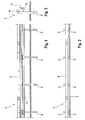
- a guard rail assembly 1 has a plurality of pillars 2 fixed to the bottom, which are driven into the ground in the example shown.
- the guard rail assembly 1 further includes a guardrail 3 and an upper longitudinal spar 4.
- the guardrail 3 and the longitudinal spar 4 are each shot in a row set profile elements, which thereby extend over the entire length of Schutzplankerlan ever 1 away.
- a deformation element 5 is arranged, which is tubular and has a substantially annular cross-section.
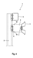
- Fig. 4 there is an attachment of the deformation element 5 to an associated post 2 at an attachment point 6, where they come to rest against each other.
- the deformation element 5 is fixed in the example shown by means of two screws on the post 2.
- the guardrail 3 in turn abuts an attachment point 7 of the deformation element 5 and is also coupled there via a screw connection.
- the upper longitudinal beam 4 is also bolted to the post 2.
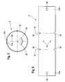
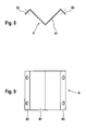
- the deformation element 5 in the present embodiment only approximately an annular cross-section, since it is formed of a metal strip 51, as in Fig. 6 is shown in a transaction.
- This sheet metal strip 51 is thereby transformed in the course of the production of the deformation element 5 such that it assumes a tubular shape, wherein ends 51a and 51b of the sheet metal strip 51 come to lie overlapping each other. in the built-in state, the overlap region is adjacent to the guardrail 3, ie this is there coupled to the deformation element 5.
- the metal strip 51 recesses 52 which serve to weaken the wall geometry of the Deforinationselements and thus form predetermined bending points S.
- two cutouts 52 formed by notches are arranged spaced apart from one another from the center of the sheet metal strip 51 at the longitudinal edges thereof.
- two mounting holes 53 In the middle area are in Fig. 6 also shown two mounting holes 53, by means of which the deformation element 5 in the installed state with an associated post 2 can be screwed.
- elongated holes 54 can be seen, through which the deformation element 5 can be screwed to the guard rail 3.
- the recesses 52 are in this case by an angle ⁇ of about 45 ° offset from the attachment point of the deformation element 5 on the post 2 against a line of action 55 before, which is formed by a connection of the attachment point 6 and the attachment point 7.
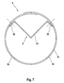
- a stiffening element 8 is shown, which is additionally arranged in the deformation elements 5 according to a further embodiment of the present invention. In this case, it is preferable to provide such a stiffening element 8 in each deformation element 5 of the guard rail arrangement 1, although this is not absolutely necessary.
- the stiffening element 8 has an angular portion 81, on whose free legs bent portions 82 and 83 are arranged. In these folds 82 and 83 are also formed holes through which the stiffening element 8 with the wall of the deformation element 5 by screws, rivets or the like can be fastened.
- the stiffening element 8 is inserted into the associated deformation element 5 such that the tip of the angular section 81 points away from the guardrail 3 and towards the post 2.
- an additional Deformafionswiderstand is activated by the deformation element stiffening according to a predetermined by the geometry of the stiffening element 8 deformation path by the stiffening element 8 with the tip of the Angular section 81 is pressed onto the pipe wall and in the result thereof, the stiffening element 8 is also plastically deformed.
- the initially relatively low deformation resistance minimizes the occupant injury risk (ASI value), whereas with increasing impact energy a higher deformation resistance is activated.
- This additional stiffening also has the further advantage that the resulting during the contact of the car tire with the guard rail post acceleration peak compared to conventional systems, such as the rammed Super Rail light variant Applicant fails lower and thus the impact severity can be further reduced.
- the invention allows, in addition to the illustrated embodiment, further design approaches.
- the predetermined bending points S may be formed instead of or in addition to the recesses 52 by slots, holes, slots or other openings in the wall of the metal strip 51.
- the wall thickness in the region of the predetermined bending points can also be reduced.
- the deformation element 5 is formed from a formed sheet metal strip; Rather, a conventional tube with an annular cross-section can certainly also be used.
- the recesses 52 or bores etc. do not have to be symmetrical to the middle of the sheet-metal strip 51 as in the embodiment shown; they can also be arranged at a different distance to the line of action 55 between the attachment point 6 and the attachment point 7 adjacent to the attachment point on the post.
- angle ⁇ between this line of action 55 and the predetermined bending points may take a different dimension than the 45 ° shown. In principle, every angle ⁇ > 0 ° to ⁇ 90 ° can be used here.
- the upper longitudinal spar 4 can also be dispensed with.
- the axis of the tubular deformation element 5 is oriented vertically, i. parallel to the longitudinal alignment of the post 2 runs.
- the deformation elements 5 can also be used, for example, with a horizontal axis.
- a plurality of deformation elements 5 between a post 2 and a guard rail 3 can be arranged.
- a plurality of predetermined bending points S may also be formed on the deformation elements 5 so as to improve the cascading effect in the plastic deformation for load transfer. In this way, the deformation behavior of a deformation element 5 can be set even more precisely.
- individual kinks can additionally be present on a deformation element, so that the same results in a one-sided weakening. This is particularly advantageous if an impact is to be expected from one side only.
- the posts 2 can also be screwed by means of floor panels with a solid surface or indirectly determined by a rear construction bottom side.
Landscapes
- Engineering & Computer Science (AREA)
- Architecture (AREA)
- Civil Engineering (AREA)
- Structural Engineering (AREA)
- Refuge Islands, Traffic Blockers, Or Guard Fence (AREA)
Applications Claiming Priority (1)
| Application Number | Priority Date | Filing Date | Title |
|---|---|---|---|
| DE200820009832 DE202008009832U1 (de) | 2008-07-22 | 2008-07-22 | Schutzplankenanordnung |
Publications (3)
| Publication Number | Publication Date |
|---|---|
| EP2148008A2 true EP2148008A2 (fr) | 2010-01-27 |
| EP2148008A3 EP2148008A3 (fr) | 2012-05-02 |
| EP2148008B1 EP2148008B1 (fr) | 2015-02-11 |
Family
ID=39829886
Family Applications (1)
| Application Number | Title | Priority Date | Filing Date |
|---|---|---|---|
| EP20090009482 Active EP2148008B1 (fr) | 2008-07-22 | 2009-07-22 | Dispositif de glissière de sécurité |
Country Status (2)
| Country | Link |
|---|---|
| EP (1) | EP2148008B1 (fr) |
| DE (1) | DE202008009832U1 (fr) |
Families Citing this family (7)
| Publication number | Priority date | Publication date | Assignee | Title |
|---|---|---|---|---|
| DE202009003752U1 (de) | 2009-03-17 | 2009-05-20 | Studiengesellschaft Für Stahlschutzplanken E.V. | Schutzplankensystem für Fahrbahnen sowie Übergangskonstruktion hierfür |
| NL2003243C2 (nl) * | 2009-07-20 | 2011-01-24 | Prins Dokkum B V | Voertuigkering, obstakelbeveiliger en werkwijze voor het keren van een voertuig en/of beschermen van een obstakel. |
| DE202010000658U1 (de) | 2010-01-07 | 2010-04-15 | Studiengesellschaft Für Stahlschutzplanken E.V. | Schutzplankenanordnung |
| DE202010009161U1 (de) * | 2010-06-16 | 2010-08-26 | Heintzmann Sicherheitssysteme Gmbh & Co. Kg | Unterfahrschutz mit Abstandhalter |
| DE202010008100U1 (de) | 2010-07-16 | 2010-09-30 | Studiengesellschaft Für Stahlschutzplanken E.V. | Schutzplankensystem, insbesondere für den Einsatz als zeitweilige entfernbare Absperrung an Verkehrsflächen |
| FR2976300B1 (fr) * | 2011-06-08 | 2016-01-29 | Rousseau | Barriere de securite pour voies de circulation et procede pour ameliorer l'absorption de l'energie d'un choc d'un vehicule leger contre une telle barriere. |
| IT201700037889A1 (it) * | 2017-04-10 | 2018-10-10 | Enzo Rillo | Barriera di sicurezza stradale - arginello stretto |
Citations (4)
| Publication number | Priority date | Publication date | Assignee | Title |
|---|---|---|---|---|
| DE3809896A1 (de) | 1988-03-24 | 1989-10-12 | Spig Schutzplanken Prod Gmbh | Schutzplankenanordnung fuer fahrbahnen |
| WO1997026411A1 (fr) | 1996-01-16 | 1997-07-24 | Studiengesellschaft Für Stahlschutzplanken E.V. | Agencement de profiles de protection |
| EP1640504A1 (fr) | 2004-09-27 | 2006-03-29 | Volkmann & Rossbach GmbH & Co. KG | Disposition de barrière routière |
| EP1719840A2 (fr) | 2005-05-04 | 2006-11-08 | Studiengesellschaft für Stahlschutzplanken e.V. | Disposition de barrière routière |
Family Cites Families (3)
| Publication number | Priority date | Publication date | Assignee | Title |
|---|---|---|---|---|
| US2078704A (en) * | 1933-01-16 | 1937-04-27 | Empire Plow Company | Highway guardrail construction |
| FR2843762B1 (fr) * | 2002-08-20 | 2011-07-29 | Jean Claude Frederic Dupuis | Barriere de securite pour voies de circulation de vehicules, comprenant des ecarteurs deformables |
| ES2220238B2 (es) * | 2004-08-04 | 2006-02-16 | Hierros Y Aplanaciones, S.A. (Hiasa) | Sistema de contencion de impactos laterales de vehiculos, con alta capacidad de contencion y de absorcion energetica. |
-
2008
- 2008-07-22 DE DE200820009832 patent/DE202008009832U1/de not_active Expired - Lifetime
-
2009
- 2009-07-22 EP EP20090009482 patent/EP2148008B1/fr active Active
Patent Citations (4)
| Publication number | Priority date | Publication date | Assignee | Title |
|---|---|---|---|---|
| DE3809896A1 (de) | 1988-03-24 | 1989-10-12 | Spig Schutzplanken Prod Gmbh | Schutzplankenanordnung fuer fahrbahnen |
| WO1997026411A1 (fr) | 1996-01-16 | 1997-07-24 | Studiengesellschaft Für Stahlschutzplanken E.V. | Agencement de profiles de protection |
| EP1640504A1 (fr) | 2004-09-27 | 2006-03-29 | Volkmann & Rossbach GmbH & Co. KG | Disposition de barrière routière |
| EP1719840A2 (fr) | 2005-05-04 | 2006-11-08 | Studiengesellschaft für Stahlschutzplanken e.V. | Disposition de barrière routière |
Also Published As
| Publication number | Publication date |
|---|---|
| EP2148008B1 (fr) | 2015-02-11 |
| EP2148008A3 (fr) | 2012-05-02 |
| DE202008009832U1 (de) | 2008-10-09 |
Similar Documents
| Publication | Publication Date | Title |
|---|---|---|
| EP2148008B1 (fr) | Dispositif de glissière de sécurité | |
| EP2455546B1 (fr) | Agencement de poteau pour une construction de glissière de sécurité et construction de glissière de sécurité pour sécuriser des bandes de roulement sur des chantiers | |
| EP3468821B1 (fr) | Pièce structurale pour véhicule à moteur avec élément de renfort | |
| EP2333159B1 (fr) | Glissière de sécurité | |
| DE102005020917A1 (de) | Schutzplankenanordnung | |
| EP2017387B1 (fr) | Agencement de profilés de protection | |
| DE202010000658U1 (de) | Schutzplankenanordnung | |
| DE102008039850B3 (de) | Fahrzeugrückhaltesystem | |
| DE102012107152B3 (de) | Stoßfängeranordnung mit Schercrashbox | |
| DE102011055960A1 (de) | Fahrzeugrückhaltesystem | |
| EP3190232B1 (fr) | Protection anti-encastrement | |
| DE202008011203U1 (de) | Fahrzeugrückhaltesystem an Verkehrswegen | |
| DE602004011657T2 (de) | Seitliche Verstärkung zur Aufname von Stossmengen für Kfz-Türen | |
| EP2037045B1 (fr) | Système de retenue de véhicule destiné à sécuriser des trajectoires | |
| EP1640504A1 (fr) | Disposition de barrière routière | |
| EP1690983A1 (fr) | Glissière de sécurité | |
| EP1640505A1 (fr) | Disposition de barrière routière | |
| EP4686785A1 (fr) | Système de retenue de véhicule | |
| DE102009044721B4 (de) | Schutzplanksystem zur Absicherung von Gefahrenstellen durch Objekte am Fahrbahnrand | |
| EP1830003A1 (fr) | Amortisseur de choc avec segments de plaques | |
| EP2792793B1 (fr) | Système de retenue pour véhicule | |
| EP2952630B1 (fr) | Système de retenue de véhicule | |
| EP2439340B1 (fr) | Système de barrière de sécurité | |
| EP1784541A1 (fr) | Systeme de retenue pour voies de circulation | |
| DE102014200030A1 (de) | Verkehrsleitelement, Verkehrsleitwand und Verwendung einer Schutzplanke |
Legal Events
| Date | Code | Title | Description |
|---|---|---|---|
| PUAI | Public reference made under article 153(3) epc to a published international application that has entered the european phase |
Free format text: ORIGINAL CODE: 0009012 |
|
| AK | Designated contracting states |
Kind code of ref document: A2 Designated state(s): AT BE BG CH CY CZ DE DK EE ES FI FR GB GR HR HU IE IS IT LI LT LU LV MC MK MT NL NO PL PT RO SE SI SK SM TR |
|
| AX | Request for extension of the european patent |
Extension state: AL BA RS |
|
| PUAL | Search report despatched |
Free format text: ORIGINAL CODE: 0009013 |
|
| AK | Designated contracting states |
Kind code of ref document: A3 Designated state(s): AT BE BG CH CY CZ DE DK EE ES FI FR GB GR HR HU IE IS IT LI LT LU LV MC MK MT NL NO PL PT RO SE SI SK SM TR |
|
| AX | Request for extension of the european patent |
Extension state: AL BA RS |
|
| RIC1 | Information provided on ipc code assigned before grant |
Ipc: E01F 15/04 20060101AFI20120326BHEP |
|
| 17P | Request for examination filed |
Effective date: 20121010 |
|
| GRAP | Despatch of communication of intention to grant a patent |
Free format text: ORIGINAL CODE: EPIDOSNIGR1 |
|
| INTG | Intention to grant announced |
Effective date: 20140904 |
|
| GRAS | Grant fee paid |
Free format text: ORIGINAL CODE: EPIDOSNIGR3 |
|
| GRAA | (expected) grant |
Free format text: ORIGINAL CODE: 0009210 |
|
| AK | Designated contracting states |
Kind code of ref document: B1 Designated state(s): AT BE BG CH CY CZ DE DK EE ES FI FR GB GR HR HU IE IS IT LI LT LU LV MC MK MT NL NO PL PT RO SE SI SK SM TR |
|
| AX | Request for extension of the european patent |
Extension state: RS |
|
| REG | Reference to a national code |
Ref country code: GB Ref legal event code: FG4D Free format text: NOT ENGLISH |
|
| REG | Reference to a national code |
Ref country code: CH Ref legal event code: EP |
|
| REG | Reference to a national code |
Ref country code: IE Ref legal event code: FG4D Free format text: LANGUAGE OF EP DOCUMENT: GERMAN |
|
| REG | Reference to a national code |
Ref country code: AT Ref legal event code: REF Ref document number: 709983 Country of ref document: AT Kind code of ref document: T Effective date: 20150315 |
|
| REG | Reference to a national code |
Ref country code: DE Ref legal event code: R096 Ref document number: 502009010589 Country of ref document: DE Effective date: 20150326 |
|
| REG | Reference to a national code |
Ref country code: NL Ref legal event code: VDEP Effective date: 20150211 |
|
| REG | Reference to a national code |
Ref country code: LT Ref legal event code: MG4D |
|
| PG25 | Lapsed in a contracting state [announced via postgrant information from national office to epo] |
Ref country code: NO Free format text: LAPSE BECAUSE OF FAILURE TO SUBMIT A TRANSLATION OF THE DESCRIPTION OR TO PAY THE FEE WITHIN THE PRESCRIBED TIME-LIMIT Effective date: 20150511 Ref country code: ES Free format text: LAPSE BECAUSE OF FAILURE TO SUBMIT A TRANSLATION OF THE DESCRIPTION OR TO PAY THE FEE WITHIN THE PRESCRIBED TIME-LIMIT Effective date: 20150211 Ref country code: SE Free format text: LAPSE BECAUSE OF FAILURE TO SUBMIT A TRANSLATION OF THE DESCRIPTION OR TO PAY THE FEE WITHIN THE PRESCRIBED TIME-LIMIT Effective date: 20150211 Ref country code: HR Free format text: LAPSE BECAUSE OF FAILURE TO SUBMIT A TRANSLATION OF THE DESCRIPTION OR TO PAY THE FEE WITHIN THE PRESCRIBED TIME-LIMIT Effective date: 20150211 Ref country code: FI Free format text: LAPSE BECAUSE OF FAILURE TO SUBMIT A TRANSLATION OF THE DESCRIPTION OR TO PAY THE FEE WITHIN THE PRESCRIBED TIME-LIMIT Effective date: 20150211 Ref country code: LT Free format text: LAPSE BECAUSE OF FAILURE TO SUBMIT A TRANSLATION OF THE DESCRIPTION OR TO PAY THE FEE WITHIN THE PRESCRIBED TIME-LIMIT Effective date: 20150211 |
|
| PG25 | Lapsed in a contracting state [announced via postgrant information from national office to epo] |
Ref country code: GR Free format text: LAPSE BECAUSE OF FAILURE TO SUBMIT A TRANSLATION OF THE DESCRIPTION OR TO PAY THE FEE WITHIN THE PRESCRIBED TIME-LIMIT Effective date: 20150512 Ref country code: NL Free format text: LAPSE BECAUSE OF FAILURE TO SUBMIT A TRANSLATION OF THE DESCRIPTION OR TO PAY THE FEE WITHIN THE PRESCRIBED TIME-LIMIT Effective date: 20150211 Ref country code: LV Free format text: LAPSE BECAUSE OF FAILURE TO SUBMIT A TRANSLATION OF THE DESCRIPTION OR TO PAY THE FEE WITHIN THE PRESCRIBED TIME-LIMIT Effective date: 20150211 Ref country code: IS Free format text: LAPSE BECAUSE OF FAILURE TO SUBMIT A TRANSLATION OF THE DESCRIPTION OR TO PAY THE FEE WITHIN THE PRESCRIBED TIME-LIMIT Effective date: 20150611 |
|
| PG25 | Lapsed in a contracting state [announced via postgrant information from national office to epo] |
Ref country code: CZ Free format text: LAPSE BECAUSE OF FAILURE TO SUBMIT A TRANSLATION OF THE DESCRIPTION OR TO PAY THE FEE WITHIN THE PRESCRIBED TIME-LIMIT Effective date: 20150211 Ref country code: RO Free format text: LAPSE BECAUSE OF FAILURE TO SUBMIT A TRANSLATION OF THE DESCRIPTION OR TO PAY THE FEE WITHIN THE PRESCRIBED TIME-LIMIT Effective date: 20150211 Ref country code: DK Free format text: LAPSE BECAUSE OF FAILURE TO SUBMIT A TRANSLATION OF THE DESCRIPTION OR TO PAY THE FEE WITHIN THE PRESCRIBED TIME-LIMIT Effective date: 20150211 Ref country code: EE Free format text: LAPSE BECAUSE OF FAILURE TO SUBMIT A TRANSLATION OF THE DESCRIPTION OR TO PAY THE FEE WITHIN THE PRESCRIBED TIME-LIMIT Effective date: 20150211 Ref country code: SK Free format text: LAPSE BECAUSE OF FAILURE TO SUBMIT A TRANSLATION OF THE DESCRIPTION OR TO PAY THE FEE WITHIN THE PRESCRIBED TIME-LIMIT Effective date: 20150211 |
|
| REG | Reference to a national code |
Ref country code: DE Ref legal event code: R097 Ref document number: 502009010589 Country of ref document: DE |
|
| PG25 | Lapsed in a contracting state [announced via postgrant information from national office to epo] |
Ref country code: PL Free format text: LAPSE BECAUSE OF FAILURE TO SUBMIT A TRANSLATION OF THE DESCRIPTION OR TO PAY THE FEE WITHIN THE PRESCRIBED TIME-LIMIT Effective date: 20150211 |
|
| PLBE | No opposition filed within time limit |
Free format text: ORIGINAL CODE: 0009261 |
|
| STAA | Information on the status of an ep patent application or granted ep patent |
Free format text: STATUS: NO OPPOSITION FILED WITHIN TIME LIMIT |
|
| PG25 | Lapsed in a contracting state [announced via postgrant information from national office to epo] |
Ref country code: IT Free format text: LAPSE BECAUSE OF FAILURE TO SUBMIT A TRANSLATION OF THE DESCRIPTION OR TO PAY THE FEE WITHIN THE PRESCRIBED TIME-LIMIT Effective date: 20150211 |
|
| 26N | No opposition filed |
Effective date: 20151112 |
|
| PG25 | Lapsed in a contracting state [announced via postgrant information from national office to epo] |
Ref country code: SI Free format text: LAPSE BECAUSE OF FAILURE TO SUBMIT A TRANSLATION OF THE DESCRIPTION OR TO PAY THE FEE WITHIN THE PRESCRIBED TIME-LIMIT Effective date: 20150211 Ref country code: MC Free format text: LAPSE BECAUSE OF FAILURE TO SUBMIT A TRANSLATION OF THE DESCRIPTION OR TO PAY THE FEE WITHIN THE PRESCRIBED TIME-LIMIT Effective date: 20150211 |
|
| REG | Reference to a national code |
Ref country code: CH Ref legal event code: PL |
|
| GBPC | Gb: european patent ceased through non-payment of renewal fee |
Effective date: 20150722 |
|
| PG25 | Lapsed in a contracting state [announced via postgrant information from national office to epo] |
Ref country code: LU Free format text: LAPSE BECAUSE OF FAILURE TO SUBMIT A TRANSLATION OF THE DESCRIPTION OR TO PAY THE FEE WITHIN THE PRESCRIBED TIME-LIMIT Effective date: 20150722 |
|
| REG | Reference to a national code |
Ref country code: IE Ref legal event code: MM4A |
|
| PG25 | Lapsed in a contracting state [announced via postgrant information from national office to epo] |
Ref country code: LI Free format text: LAPSE BECAUSE OF NON-PAYMENT OF DUE FEES Effective date: 20150731 Ref country code: GB Free format text: LAPSE BECAUSE OF NON-PAYMENT OF DUE FEES Effective date: 20150722 Ref country code: CH Free format text: LAPSE BECAUSE OF NON-PAYMENT OF DUE FEES Effective date: 20150731 |
|
| REG | Reference to a national code |
Ref country code: FR Ref legal event code: ST Effective date: 20160331 |
|
| PG25 | Lapsed in a contracting state [announced via postgrant information from national office to epo] |
Ref country code: FR Free format text: LAPSE BECAUSE OF NON-PAYMENT OF DUE FEES Effective date: 20150731 |
|
| PG25 | Lapsed in a contracting state [announced via postgrant information from national office to epo] |
Ref country code: IE Free format text: LAPSE BECAUSE OF NON-PAYMENT OF DUE FEES Effective date: 20150722 |
|
| REG | Reference to a national code |
Ref country code: AT Ref legal event code: MM01 Ref document number: 709983 Country of ref document: AT Kind code of ref document: T Effective date: 20150722 |
|
| PGFP | Annual fee paid to national office [announced via postgrant information from national office to epo] |
Ref country code: DE Payment date: 20160704 Year of fee payment: 8 |
|
| PG25 | Lapsed in a contracting state [announced via postgrant information from national office to epo] |
Ref country code: AT Free format text: LAPSE BECAUSE OF NON-PAYMENT OF DUE FEES Effective date: 20150722 |
|
| PG25 | Lapsed in a contracting state [announced via postgrant information from national office to epo] |
Ref country code: MT Free format text: LAPSE BECAUSE OF FAILURE TO SUBMIT A TRANSLATION OF THE DESCRIPTION OR TO PAY THE FEE WITHIN THE PRESCRIBED TIME-LIMIT Effective date: 20150211 |
|
| PG25 | Lapsed in a contracting state [announced via postgrant information from national office to epo] |
Ref country code: SM Free format text: LAPSE BECAUSE OF FAILURE TO SUBMIT A TRANSLATION OF THE DESCRIPTION OR TO PAY THE FEE WITHIN THE PRESCRIBED TIME-LIMIT Effective date: 20150211 Ref country code: HU Free format text: LAPSE BECAUSE OF FAILURE TO SUBMIT A TRANSLATION OF THE DESCRIPTION OR TO PAY THE FEE WITHIN THE PRESCRIBED TIME-LIMIT; INVALID AB INITIO Effective date: 20090722 Ref country code: BG Free format text: LAPSE BECAUSE OF FAILURE TO SUBMIT A TRANSLATION OF THE DESCRIPTION OR TO PAY THE FEE WITHIN THE PRESCRIBED TIME-LIMIT Effective date: 20150211 |
|
| PG25 | Lapsed in a contracting state [announced via postgrant information from national office to epo] |
Ref country code: CY Free format text: LAPSE BECAUSE OF FAILURE TO SUBMIT A TRANSLATION OF THE DESCRIPTION OR TO PAY THE FEE WITHIN THE PRESCRIBED TIME-LIMIT Effective date: 20150211 |
|
| PG25 | Lapsed in a contracting state [announced via postgrant information from national office to epo] |
Ref country code: BE Free format text: LAPSE BECAUSE OF NON-PAYMENT OF DUE FEES Effective date: 20150731 |
|
| PG25 | Lapsed in a contracting state [announced via postgrant information from national office to epo] |
Ref country code: TR Free format text: LAPSE BECAUSE OF FAILURE TO SUBMIT A TRANSLATION OF THE DESCRIPTION OR TO PAY THE FEE WITHIN THE PRESCRIBED TIME-LIMIT Effective date: 20150211 |
|
| REG | Reference to a national code |
Ref country code: DE Ref legal event code: R119 Ref document number: 502009010589 Country of ref document: DE |
|
| PG25 | Lapsed in a contracting state [announced via postgrant information from national office to epo] |
Ref country code: DE Free format text: LAPSE BECAUSE OF NON-PAYMENT OF DUE FEES Effective date: 20180201 |
|
| PG25 | Lapsed in a contracting state [announced via postgrant information from national office to epo] |
Ref country code: MK Free format text: LAPSE BECAUSE OF FAILURE TO SUBMIT A TRANSLATION OF THE DESCRIPTION OR TO PAY THE FEE WITHIN THE PRESCRIBED TIME-LIMIT Effective date: 20150211 Ref country code: PT Free format text: LAPSE BECAUSE OF FAILURE TO SUBMIT A TRANSLATION OF THE DESCRIPTION OR TO PAY THE FEE WITHIN THE PRESCRIBED TIME-LIMIT Effective date: 20150211 |