EP2148042A2 - Pale de rotor avec l'extrémité partiellement oblique - Google Patents
Pale de rotor avec l'extrémité partiellement oblique Download PDFInfo
- Publication number
- EP2148042A2 EP2148042A2 EP09251339A EP09251339A EP2148042A2 EP 2148042 A2 EP2148042 A2 EP 2148042A2 EP 09251339 A EP09251339 A EP 09251339A EP 09251339 A EP09251339 A EP 09251339A EP 2148042 A2 EP2148042 A2 EP 2148042A2
- Authority
- EP
- European Patent Office
- Prior art keywords
- blade
- winglet
- cavity
- peripheral wall
- region
- Prior art date
- Legal status (The legal status is an assumption and is not a legal conclusion. Google has not performed a legal analysis and makes no representation as to the accuracy of the status listed.)
- Granted
Links
- 230000002093 peripheral effect Effects 0.000 claims abstract description 43
- 238000001816 cooling Methods 0.000 claims description 52
- 230000007704 transition Effects 0.000 claims description 7
- 230000000694 effects Effects 0.000 claims description 4
- 238000005192 partition Methods 0.000 claims description 3
- 239000012809 cooling fluid Substances 0.000 claims description 2
- 238000005553 drilling Methods 0.000 description 2
- 238000013459 approach Methods 0.000 description 1
- 230000003292 diminished effect Effects 0.000 description 1
- 230000002708 enhancing effect Effects 0.000 description 1
- 239000002184 metal Substances 0.000 description 1
- 238000007789 sealing Methods 0.000 description 1
- 230000003068 static effect Effects 0.000 description 1
- 238000011144 upstream manufacturing Methods 0.000 description 1
Images


Classifications
-
- F—MECHANICAL ENGINEERING; LIGHTING; HEATING; WEAPONS; BLASTING
- F01—MACHINES OR ENGINES IN GENERAL; ENGINE PLANTS IN GENERAL; STEAM ENGINES
- F01D—NON-POSITIVE DISPLACEMENT MACHINES OR ENGINES, e.g. STEAM TURBINES
- F01D5/00—Blades; Blade-carrying members; Heating, heat-insulating, cooling or antivibration means on the blades or the members
- F01D5/12—Blades
- F01D5/14—Form or construction
- F01D5/141—Shape, i.e. outer, aerodynamic form
-
- F—MECHANICAL ENGINEERING; LIGHTING; HEATING; WEAPONS; BLASTING
- F01—MACHINES OR ENGINES IN GENERAL; ENGINE PLANTS IN GENERAL; STEAM ENGINES
- F01D—NON-POSITIVE DISPLACEMENT MACHINES OR ENGINES, e.g. STEAM TURBINES
- F01D5/00—Blades; Blade-carrying members; Heating, heat-insulating, cooling or antivibration means on the blades or the members
- F01D5/12—Blades
- F01D5/14—Form or construction
- F01D5/20—Specially-shaped blade tips to seal space between tips and stator
-
- F—MECHANICAL ENGINEERING; LIGHTING; HEATING; WEAPONS; BLASTING
- F05—INDEXING SCHEMES RELATING TO ENGINES OR PUMPS IN VARIOUS SUBCLASSES OF CLASSES F01-F04
- F05D—INDEXING SCHEME FOR ASPECTS RELATING TO NON-POSITIVE-DISPLACEMENT MACHINES OR ENGINES, GAS-TURBINES OR JET-PROPULSION PLANTS
- F05D2250/00—Geometry
- F05D2250/30—Arrangement of components
- F05D2250/31—Arrangement of components according to the direction of their main axis or their axis of rotation
- F05D2250/314—Arrangement of components according to the direction of their main axis or their axis of rotation the axes being inclined in relation to each other
-
- F—MECHANICAL ENGINEERING; LIGHTING; HEATING; WEAPONS; BLASTING
- F05—INDEXING SCHEMES RELATING TO ENGINES OR PUMPS IN VARIOUS SUBCLASSES OF CLASSES F01-F04
- F05D—INDEXING SCHEME FOR ASPECTS RELATING TO NON-POSITIVE-DISPLACEMENT MACHINES OR ENGINES, GAS-TURBINES OR JET-PROPULSION PLANTS
- F05D2260/00—Function
- F05D2260/20—Heat transfer, e.g. cooling
- F05D2260/201—Heat transfer, e.g. cooling by impingement of a fluid
Definitions
- This invention relates to a blade for a rotor, and is particularly, although not exclusively, concerned with a blade such as a turbine blade for a rotor to be used in a gas turbine engine.
- EP 0801209 discloses a turbine rotor blade which, at its radially outer end, has a cavity or passage defined by a peripheral wall which has an aperture at the trailing edge of the blade.
- the peripheral wall extends radially from lateral projections on opposite sides of the blade.
- the function of the cavity is to trap gas which leaks past the peripheral wall on the pressure side of the blade. The trapped gas forms a vortex within the cavity, and flows from the cavity through the aperture at the trailing edge. This configuration serves to avoid losses in efficiency caused by gas leakage over the turbine blade tips and also to avoid losses caused by flow disturbances set up by the leakage flow.
- Such configurations at the tip of a rotor blade are sometimes referred to as "squealer tips".
- a cooling arrangement for a squealer tip is disclosed in US 6164914 . Air is bled from a cooling circuit within the blade to a plenum situated just beneath the squealer tip. Air flows into the plenum through impingement holes which direct jets of air at the internal surfaces of a tip cap forming the base of the cavity between the peripheral walls at the junction between the tip cap and the peripheral walls.
- the squealer tip configuration of EP 0801209 comprises a relatively massive structure constituted by the peripheral wall itself and the lateral extensions of the blade which support it. This additional mass generates high mechanical stresses, particularly at the connection between the blade and the rotor hub. This imposes a limitation on the maximum rotational speed of the rotor. There are also difficulties associated with cooling of the peripheral wall and the lateral extensions, since they are situated away from the main aerofoil section of the blade in which a cooling circuit may be provided. Adequate cooling consequently requires an increased supply of cooling air, leading to reduced engine efficiency.
- the cooling arrangement disclosed in US 6164914 uses a common plenum for supplying cooling air for cooling both the pressure and suction sides of the blade. Air passing through the impingement holes is drawn from different parts of the cooling circuit within the main body of the blade, and consequently air flowing through different impingement holes has different temperatures. There are therefore difficulties in controlling the cooling effectiveness of the air delivered through the impingement holes, and it is difficult to localise cooling to specific hot spots, for example at the trailing edge region of the blade.
- a blade for a rotor having an aerofoil surface comprising pressure and suction sides extending between a leading edge and a trailing edge of the aerofoil surface, and having a squealer tip comprising a peripheral wall surrounding a cavity which is open at a radial end of the blade and at the trailing edge of the blade, wherein the peripheral wall comprises at least one first region which extends radially and has an outer surface which is a continuation of the aerofoil surface, and at least one second region which is inclined outwardly of the cavity with respect to the radial direction, and has an outer surface which extends obliquely outwardly of the blade from the aerofoil surface along part of at least one of the pressure side and suction side.
- radial refers to the axis of the rotor on which the blade is, or is intended to be, mounted. It will be appreciated that these terms are not used in a precise geometrical sense, since the aerofoil surface of the blade has a complex curvature, and the blade may not extend exactly radially of the rotor axis over its entire length.
- the second region may comprise a pressure side winglet extending along part of the pressure side of the aerofoil surface.
- the pressure side winglet extends from a leading end positioned between the leading edge and the trailing edge of the aerofoil surface, to a trailing end situated at the opening of the cavity at the trailing edge of the aerofoil surface. Consequently, the pressure side winglet may terminate, at its trailing end, at the end of the peripheral wall on the pressure side of the aerofoil surface.
- the leading end of the pressure side winglet may be situated approximately midway between the leading edge and the trailing edge of the aerofoil surface. In other words, the leading end of the pressure side winglet may be situated approximately 50% of the distance along the chordwise width of the blade. In another embodiment, the pressure side winglet may extend between its leading end and trailing end from a position approximately 20% along the chordwise width of the blade from the leading edge to a position approximately 70% along the chordwise width.
- the second region may comprise a suction side winglet extending along part of the suction side of the aerofoil surface.
- the suction side winglet may extend from a leading end situated approximately 60% along the chordwise width of the blade from the leading edge to the trailing edge of the blade.
- the suction side winglet extends from a leading end positioned approximately in the range of about 40% to about 90% of the chordwise distance from the leading edge, to the trailing edge.
- the peripheral wall may have a radially inner portion extending radially, with an outer surface which is a continuation of the aerofoil surface, and a radially outer portion which is inclined outwardly of the cavity with respect to the radial direction and has an outer surface extending obliquely outwardly of the blade from the aerofoil surface.
- the or each winglet and the first portion of the peripheral wall may terminate at their radially outer ends in end surfaces which lie in a common plane.
- the common plane may be arcuate, conforming to the profile of an inner surface of a casing part within which the rotor rotates.
- the end surface of the or each winglet may vary in circumferential width along the length of the winglet and thus may increase in width from the leading end to an intermediate region of the winglet, and then decrease in width towards the trailing end of the winglet.
- the peripheral wall may extend radially outwardly from a partition which defines the base of the cavity.
- the ratio of the width of the cavity to the depth of the cavity may be in the range 1 to 5 along the length of the cavity between the leading edge and the trailing edge of the aerofoil surface.
- the blade may be provided with a cooling passage which has an extension projecting into the peripheral wall on one side of the cavity, the extension communicating through at least one duct with a chamber extending into the peripheral wall on the other side of the cavity, the duct, or at least one of the ducts, being configured to admit cooling fluid through the chamber in a manner to effect impingement cooling of an internal surface of the chamber.
- the chamber may communicate with the exterior of the blade through film cooling holes, at least one of which may emerge into the cavity. If the peripheral wall comprises a pressure side winglet and a suction side winglet, the extension may project into the pressure side winglet, and the chamber may extend into the suction side winglet.
- the present invention also provides a rotor including an array of blades, each as defined above.
- a further aspect of the present invention provides a gas turbine engine provided with such a rotor.
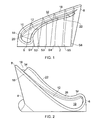
- the blade shown in Figures 1 and 2 has an aerofoil surface made up of a pressure side 2 and a suction side 4, both extending from a leading edge 6 to a trailing edge 8.
- the radial tip of the blade is formed as a squealer tip, comprising a partition 10 and a peripheral wall 14, which define a cavity 12.
- the cavity 12 is open at the radial tip of the blade, and, through an opening 16 at the trailing edge 8 of the blade.
- the peripheral wall 14 comprises a first region 18 which extends from the trailing edge 8 over the suction surface 4, round the leading edge 6 and part of the way along the pressure surface 2.
- This first region 18 extends generally radially, and its outer surface 20 is a smooth continuation of the profile of the aerofoil surface, both on the pressure side 2 and the suction side 4.
- the peripheral wall 14 also has a second region 22 which is in the form of a winglet extending generally over the rear (ie nearer the trailing edge 8) portion of the pressure side of the blade tip.
- This second region 22 as is clear from sections S4 and S5 in Figure 3 , is inclined outwardly of the cavity 12 with respect to the radial direction.
- the outer surface of the winglet is thus also inclined to the pressure side of the aerofoil surface.
- transition region 26 shown in sections S2 and S3 in Figure 3 .
- the peripheral wall 14 has two portions, namely a first portion 28 which extends radially, like the first region 18, and a second portion 30, which is inclined, like the second region or winglet 22.
- first portion 28 which extends radially, like the first region 18, and a second portion 30, which is inclined, like the second region or winglet 22.
- the winglet 22 extends from a leading end 32, which is situated approximately midway between the leading and trailing edges 6, 8, ie 50% of the chordwise distance from the leading edge 6 to the trailing edge 8, to the trailing edge 8, or, more precisely, to the region of the trailing edge 8 defined by the end 34 of the peripheral wall 14 on the pressure side 2.
- the transition region 26 extends, in the embodiment shown in Figures 1 to 3 , from a position approximately 25% of the chordwise distance from the leading edge 6 to the trailing edge 8, to the leading end 32 of the winglet 22.
- the winglet 22 is inclined from the radial direction, it has the effect of widening the cavity 12 as it approaches the trailing edge 8. The result is that, in use of the blade, gas leaking over the peripheral wall 14 on the pressure side 2 will, over the full extent of the pressure side 2, encounter a region of the cavity 12 having a width which is sufficiently large to enable the overflowing air to reattach within the cavity 12 and so remain captured until it is discharged through the opening 16 at the trailing edge 8.
- the width of the cavity 12 may vary in the chordwise direction, the ratio of the width of the cavity 12 to its depth may typically be maintained within the range 1 to 5, and where possible 1.5 to 5.
- the width increase in the trailing edge region of the blade by forming the peripheral wall 14 as the winglet 22, enhanced sealing against leakage over the blade tip can be achieved without significant weight penalty. While most of the gas entering the cavity 12 will be discharged through the opening 16 at the trailing edge 8, some may leak over the peripheral wall 14 on the suction side 4. This leakage will interact and roll up with a secondary vortex generated in the main gas flow stream flowing over the suction side 4. However, owing to the increased width of the cavity 12, this leakage, and the loss induced by the over-tip leakage vortex, is diminished.
- the winglet 22 is situated at a region of the blade tip which is exposed to the hottest gas flowing from upstream nozzle guide vanes.
- the position of the winglet 22 at the rearward end of the pressure side provides easier access to cooling air from internal passages within the blade, leading to enhanced cooling.
- FIGs 4 and 5 shown an alternative embodiment. For convenience, features in common with the embodiment shown in Figures 1 to 3 are indicated by the same reference numbers.
- the winglet 22, comprising a second region of the peripheral wall 14, is displaced further towards the leading edge 6 than the winglet 22 in the embodiment of Figures 1 to 3 . Furthermore, an additional second region of the peripheral wall 14 is provided on the suction side 4, in the form of a winglet 36.
- the interior of the blade is provided with a cooling circuit which includes a passage 38 which extends chordwise of the blade from a position close to the leading edge 6 (S1) to a position close to the trailing edge 8 (S5).
- the cooling passage 38 includes an extension 40 which projects into the pressure side winglet 22, so enhancing cooling in this region.
- the cooling passage 38 it would be possible also for the cooling passage 38 to have an extension projecting into the suction side winglet 36, for example at section 4. This is possible because the additional thickness obtained from the profile of the winglet 36 provides sufficient metal to accommodate the required internal cooling circuit.
- the pressure side winglet 22 extends from a leading end 32 which is at a position approximately 20% along the chordwise length of the blade from the leading edge 6.
- the trailing edge of the winglet 22 is situated approximately 70% of the distance along the chordwise direction from the leading edge 6, at a point where the peripheral wall 14 drops in height to form a ledge 42 over which gas emerging from the cavity 12 can flow.
- the suction side winglet 36 is situated towards the trailing edge 8, and, in the embodiment shown, extends from a leading end 44 position approximately 65% along the chordwise distance of the blade, to a trailing end situated at the trailing edge 8 of the blade.
- the pressure side winglet 22 is configured and positioned to create a greater pressure drop in the on-coming tip swirl flow which is predominant in the middle region between the leading and trailing edges 6, 8.
- Both the pressure side winglet 22 and the suction side winglet 36 serve to increase the width of the cavity 12 so as to cause leakage flow to trip over the peripheral wall 14 on the pressure side 2, and to reattach within the cavity 12, as mentioned above with regard to Figures 1 and 3 .
- the ratio of the width to the depth of the cavity 12 is typically in the range 1 to 5.
- Figures 6 to 9 The embodiment shown in Figures 6 to 9 is similar to that of Figures 4 and 5 in terms of the external contours of the blade. However, Figures 6 and 7 also represent the internal cooling circuit of the blade by way of a core 46 which is used to form it.
- Figure 9 is a sectional end on view in the direction of arrow "A" in Figure 6 .
- the cooling circuit comprises a passage 38, as shown in Figure 5 , with an extension 40 into the pressure side winglet 22.
- columns 48 formed by holes 50 in the core, extend completely or partially across the passage 38 to enhance heat transfer.
- the columns 48 may also act as localised flow restrictors which, in operation, meter air passing between them to control the flow of air exiting from the trailing edge.
- a chamber 52 is branched from the extension 40 at a position approximately 50% of the chordwise width from the leading edge 6.
- the chamber 52 extends towards the trailing edge of the blade, as indicated in sections S3 and S4.
- the connection between the chamber 52 and the extension 50 is provided by one or more channels 54 (only one shown in Figures 6 and 7 ).
- the channel 54 is configured as an impingement channel, so that cooling air flowing into the chamber 52 from the extension 40 is directed as an impingement jet against an internal surface of the chamber 52 to enhance heat transfer.
- Cooling passages 53 are provided in the wall of the chamber 52, and are configured to exhaust cooling air from the chamber 52 such that, in use, the chamber 52 has a lower static pressure than the passage 38. Hence air will be drawn from the chamber 38 along the channel 54 to impinge on the internal surface of chamber 52. Thus heat transfer is increased in this region beyond that which could be achieved by convection cooling alone in this arrangement.
- Additional film cooling holes may be provided to convey cooling air from the cooling circuit 38 (including the extension 40 and the chamber 52) to the exterior surface of the blade in order to provide film cooling.
- the film cooling passages may emerge on the aerofoil surface of the blade, but at least some of them may emerge from the base 10 or the peripheral wall 14 to provide film cooling of these components within the cavity 12. Similar film cooling passages may be provided in the embodiments shown in Figures 1 to 5 .
- the cooling arrangement shown in Figures 6 to 9 enables relatively cool cooling air to be supplied to the peripheral wall 14 on both the pressure and suction sides 2, 4.
- the cooling circuit within the blade is configured as a multi-pass arrangement in which cooling air flows in series through radial passages interconnected at bends at the radially inner and outer end regions of the blade, the air for the passage 38, and the extension 40 can be drawn from the first or second of the radial passages within the blade, where the air is relatively cool, compared with the air reaching the trailing edge region of the blade after several passes along the blade in the radial direction. Consequently, the air reaching the chamber 52 is also relatively cool, and this configuration is therefore capable of providing effective cooling for regions of the blade tip that are subjected to hot gas flows.
- impingement cooling within the chamber 52 enables this region of the peripheral wall 14 to be cooled by internal air flow, rather than by film cooling. This reduces the requirement for film cooling holes, so reducing the loss of air for cooling purposes, with a consequent increase in engine efficiency.
- the chamber 52, the channel or channels 54 and the extension 40 may be formed by use of a single core 46. This eliminates mechanical stresses resulting from drilling operations otherwise required to form these features, and also avoids the need to weld off holes formed as part of the drilling operation.
- peripheral wall 14, including the winglets 22 and 36 terminate at faces 56 which all lie in a common plane.
- faces 56 are, in fact, profiled to conform to the curvature of the internal surface of an engine casing along which the blade tip moves during rotation of the rotor.
- the cooling passage extension 40 is shown provided in the pressure side winglet 22 and the chamber 52 in the suction side winglet 36. In a further embodiment, the cooling passage extension 40 is provided in the suction side winglet 36 and the chamber 52 in the pressure side winglet 22.
Landscapes
- Engineering & Computer Science (AREA)
- Mechanical Engineering (AREA)
- General Engineering & Computer Science (AREA)
- Physics & Mathematics (AREA)
- Fluid Mechanics (AREA)
- Turbine Rotor Nozzle Sealing (AREA)
Applications Claiming Priority (2)
| Application Number | Priority Date | Filing Date | Title |
|---|---|---|---|
| GBGB0813556.8A GB0813556D0 (en) | 2008-07-24 | 2008-07-24 | A blade for a rotor |
| GB0815542A GB2462131B (en) | 2008-07-24 | 2008-08-27 | A Blade for a rotor |
Publications (3)
| Publication Number | Publication Date |
|---|---|
| EP2148042A2 true EP2148042A2 (fr) | 2010-01-27 |
| EP2148042A3 EP2148042A3 (fr) | 2015-08-12 |
| EP2148042B1 EP2148042B1 (fr) | 2017-11-29 |
Family
ID=39746864
Family Applications (1)
| Application Number | Title | Priority Date | Filing Date |
|---|---|---|---|
| EP09251339.9A Not-in-force EP2148042B1 (fr) | 2008-07-24 | 2009-05-18 | Pale de rotor avec l'extrémité partiellement oblique |
Country Status (3)
| Country | Link |
|---|---|
| US (1) | US8246307B2 (fr) |
| EP (1) | EP2148042B1 (fr) |
| GB (2) | GB0813556D0 (fr) |
Cited By (10)
| Publication number | Priority date | Publication date | Assignee | Title |
|---|---|---|---|---|
| FR2983517A1 (fr) * | 2011-12-06 | 2013-06-07 | Snecma | Aube de turbine refroidie pour moteur a turbine a gaz. |
| US8840361B2 (en) | 2010-09-09 | 2014-09-23 | Rolls-Royce Plc | Fan blade with winglet |
| EP3138997A1 (fr) * | 2015-09-02 | 2017-03-08 | General Electric Company | Configurations de pointes d'aube de rotor de turbine |
| WO2019035800A1 (fr) * | 2017-08-14 | 2019-02-21 | Siemens Aktiengesellschaft | Aubes de turbine |
| EP3477059A1 (fr) * | 2017-10-26 | 2019-05-01 | Siemens Aktiengesellschaft | Surface portante de compresseur |
| US10443405B2 (en) | 2017-05-10 | 2019-10-15 | General Electric Company | Rotor blade tip |
| US10830082B2 (en) | 2017-05-10 | 2020-11-10 | General Electric Company | Systems including rotor blade tips and circumferentially grooved shrouds |
| US11136890B1 (en) | 2020-03-25 | 2021-10-05 | General Electric Company | Cooling circuit for a turbomachine component |
| US11299991B2 (en) | 2020-04-16 | 2022-04-12 | General Electric Company | Tip squealer configurations |
| US12123319B2 (en) | 2020-12-30 | 2024-10-22 | Ge Infrastructure Technology Llc | Cooling circuit having a bypass conduit for a turbomachine component |
Families Citing this family (25)
| Publication number | Priority date | Publication date | Assignee | Title |
|---|---|---|---|---|
| US8414265B2 (en) * | 2009-10-21 | 2013-04-09 | General Electric Company | Turbines and turbine blade winglets |
| US8628299B2 (en) * | 2010-01-21 | 2014-01-14 | General Electric Company | System for cooling turbine blades |
| US8777567B2 (en) | 2010-09-22 | 2014-07-15 | Honeywell International Inc. | Turbine blades, turbine assemblies, and methods of manufacturing turbine blades |
| GB201100957D0 (en) | 2011-01-20 | 2011-03-02 | Rolls Royce Plc | Rotor blade |
| US9051843B2 (en) * | 2011-10-28 | 2015-06-09 | General Electric Company | Turbomachine blade including a squeeler pocket |
| US10087764B2 (en) * | 2012-03-08 | 2018-10-02 | Pratt & Whitney Canada Corp. | Airfoil for gas turbine engine |
| US9593584B2 (en) * | 2012-10-26 | 2017-03-14 | Rolls-Royce Plc | Turbine rotor blade of a gas turbine |
| DE102012021400A1 (de) | 2012-10-31 | 2014-04-30 | Rolls-Royce Deutschland Ltd & Co Kg | Turbinenrotorschaufel einer Gasturbine |
| JP6086583B2 (ja) * | 2012-11-28 | 2017-03-01 | 三菱日立パワーシステムズ株式会社 | タービン動翼 |
| US9856739B2 (en) | 2013-09-18 | 2018-01-02 | Honeywell International Inc. | Turbine blades with tip portions having converging cooling holes |
| US9816389B2 (en) * | 2013-10-16 | 2017-11-14 | Honeywell International Inc. | Turbine rotor blades with tip portion parapet wall cavities |
| US9879544B2 (en) | 2013-10-16 | 2018-01-30 | Honeywell International Inc. | Turbine rotor blades with improved tip portion cooling holes |
| EP2886798B1 (fr) | 2013-12-20 | 2018-10-24 | Rolls-Royce Corporation | Trous de refroidissement de film usinés mécaniquement |
| CA2936186C (fr) * | 2014-01-17 | 2023-02-28 | General Electric Company | Bout aminci d'aube de turbine composite a matrice ceramique ayant un evasement, et procede associe |
| EP2987956A1 (fr) * | 2014-08-18 | 2016-02-24 | Siemens Aktiengesellschaft | Aube de compresseur |
| US20160319672A1 (en) * | 2015-04-29 | 2016-11-03 | General Electric Company | Rotor blade having a flared tip |
| US10107108B2 (en) | 2015-04-29 | 2018-10-23 | General Electric Company | Rotor blade having a flared tip |
| CN105179022B (zh) * | 2015-09-30 | 2017-06-27 | 北京大学 | 一种采用叶顶肋翼结构的涡轮叶片 |
| US10253637B2 (en) | 2015-12-11 | 2019-04-09 | General Electric Company | Method and system for improving turbine blade performance |
| EP3421725A1 (fr) * | 2017-06-26 | 2019-01-02 | Siemens Aktiengesellschaft | Aube de compresseur |
| US10787932B2 (en) | 2018-07-13 | 2020-09-29 | Honeywell International Inc. | Turbine blade with dust tolerant cooling system |
| CN112282855B (zh) * | 2020-09-27 | 2022-08-16 | 哈尔滨工业大学 | 涡轮叶片 |
| CN112283160B (zh) * | 2020-12-24 | 2021-03-12 | 中国航发上海商用航空发动机制造有限责任公司 | 压气机转子叶片及其设计方法 |
| US11608746B2 (en) | 2021-01-13 | 2023-03-21 | General Electric Company | Airfoils for gas turbine engines |
| FR3151629A1 (fr) * | 2023-07-25 | 2025-01-31 | Safran Aircraft Engines | Roue mobile pour turbomachine comprenant des aubes equipées d’une ailette |
Citations (2)
| Publication number | Priority date | Publication date | Assignee | Title |
|---|---|---|---|---|
| EP0801209A2 (fr) | 1996-04-12 | 1997-10-15 | ROLLS-ROYCE plc | Dispositif d'étanchéité pour les extrémités des aubes mobiles de turbine |
| US6164914A (en) | 1999-08-23 | 2000-12-26 | General Electric Company | Cool tip blade |
Family Cites Families (7)
| Publication number | Priority date | Publication date | Assignee | Title |
|---|---|---|---|---|
| US6494678B1 (en) * | 2001-05-31 | 2002-12-17 | General Electric Company | Film cooled blade tip |
| US6790005B2 (en) * | 2002-12-30 | 2004-09-14 | General Electric Company | Compound tip notched blade |
| GB2409006B (en) * | 2003-12-11 | 2006-05-17 | Rolls Royce Plc | Tip sealing for a turbine rotor blade |
| GB2413160B (en) * | 2004-04-17 | 2006-08-09 | Rolls Royce Plc | Turbine rotor blades |
| US7290986B2 (en) * | 2005-09-09 | 2007-11-06 | General Electric Company | Turbine airfoil with curved squealer tip |
| US7607893B2 (en) * | 2006-08-21 | 2009-10-27 | General Electric Company | Counter tip baffle airfoil |
| FR2907157A1 (fr) * | 2006-10-13 | 2008-04-18 | Snecma Sa | Aube mobile de turbomachine |
-
2008
- 2008-07-24 GB GBGB0813556.8A patent/GB0813556D0/en not_active Ceased
- 2008-08-27 GB GB0815542A patent/GB2462131B/en not_active Expired - Fee Related
-
2009
- 2009-05-18 EP EP09251339.9A patent/EP2148042B1/fr not_active Not-in-force
- 2009-07-01 US US12/458,148 patent/US8246307B2/en active Active
Patent Citations (2)
| Publication number | Priority date | Publication date | Assignee | Title |
|---|---|---|---|---|
| EP0801209A2 (fr) | 1996-04-12 | 1997-10-15 | ROLLS-ROYCE plc | Dispositif d'étanchéité pour les extrémités des aubes mobiles de turbine |
| US6164914A (en) | 1999-08-23 | 2000-12-26 | General Electric Company | Cool tip blade |
Cited By (13)
| Publication number | Priority date | Publication date | Assignee | Title |
|---|---|---|---|---|
| US8840361B2 (en) | 2010-09-09 | 2014-09-23 | Rolls-Royce Plc | Fan blade with winglet |
| US9435210B2 (en) | 2011-12-06 | 2016-09-06 | Snecma | Cooled turbine blade for gas turbine engine |
| FR2983517A1 (fr) * | 2011-12-06 | 2013-06-07 | Snecma | Aube de turbine refroidie pour moteur a turbine a gaz. |
| EP3138997A1 (fr) * | 2015-09-02 | 2017-03-08 | General Electric Company | Configurations de pointes d'aube de rotor de turbine |
| US10443405B2 (en) | 2017-05-10 | 2019-10-15 | General Electric Company | Rotor blade tip |
| US10830082B2 (en) | 2017-05-10 | 2020-11-10 | General Electric Company | Systems including rotor blade tips and circumferentially grooved shrouds |
| WO2019035800A1 (fr) * | 2017-08-14 | 2019-02-21 | Siemens Aktiengesellschaft | Aubes de turbine |
| WO2019081471A1 (fr) * | 2017-10-26 | 2019-05-02 | Siemens Aktiengesellschaft | Aube de compresseur |
| EP3477059A1 (fr) * | 2017-10-26 | 2019-05-01 | Siemens Aktiengesellschaft | Surface portante de compresseur |
| US11274558B2 (en) | 2017-10-26 | 2022-03-15 | Siemens Energy Global GmbH & Co. KG | Compressor aerofoil |
| US11136890B1 (en) | 2020-03-25 | 2021-10-05 | General Electric Company | Cooling circuit for a turbomachine component |
| US11299991B2 (en) | 2020-04-16 | 2022-04-12 | General Electric Company | Tip squealer configurations |
| US12123319B2 (en) | 2020-12-30 | 2024-10-22 | Ge Infrastructure Technology Llc | Cooling circuit having a bypass conduit for a turbomachine component |
Also Published As
| Publication number | Publication date |
|---|---|
| US8246307B2 (en) | 2012-08-21 |
| GB2462131B (en) | 2010-07-21 |
| EP2148042B1 (fr) | 2017-11-29 |
| EP2148042A3 (fr) | 2015-08-12 |
| GB0813556D0 (en) | 2008-09-03 |
| GB2462131A (en) | 2010-01-27 |
| US20100098554A1 (en) | 2010-04-22 |
| GB0815542D0 (en) | 2008-10-01 |
Similar Documents
| Publication | Publication Date | Title |
|---|---|---|
| EP2148042B1 (fr) | Pale de rotor avec l'extrémité partiellement oblique | |
| US6283708B1 (en) | Coolable vane or blade for a turbomachine | |
| US6616406B2 (en) | Airfoil trailing edge cooling construction | |
| EP0971095B1 (fr) | Aube refroidissable pour turbines à gaz | |
| US8083485B2 (en) | Angled tripped airfoil peanut cavity | |
| EP0992654B1 (fr) | Orifices de refroidissement pour des composants de turbines à gaz | |
| JP4876043B2 (ja) | フレア先端式タービンブレード | |
| US8057181B1 (en) | Multiple expansion film cooling hole for turbine airfoil | |
| EP2365188B1 (fr) | Refroidissement de composants de turbine à gaz comprenant des canaux dans les rainures de joints | |
| EP3748126B1 (fr) | Composants pour moteurs à turbine à gaz | |
| US10577943B2 (en) | Turbine engine airfoil insert | |
| EP3399145B1 (fr) | Profil d'aube avec cavité hybride de bord d'attaque | |
| US10590779B2 (en) | Double wall turbine gas turbine engine blade cooling configuration | |
| US10082031B2 (en) | Rotor of a turbine of a gas turbine with improved cooling air routing | |
| CN110832168B (zh) | 用于冲击冷却的涡轮组件及组装方法 | |
| US20200024951A1 (en) | Component for a turbine engine with a cooling hole | |
| EP3508696B1 (fr) | Configuration de refroidissement de plate-forme et d'aube de moteur à turbine à gaz | |
| EP3064712B1 (fr) | Profil aérodynamique d'aube avec insert de chicane | |
| US11391161B2 (en) | Component for a turbine engine with a cooling hole | |
| EP1213442B1 (fr) | Aube rotorique | |
| EP3647544B1 (fr) | Profil d'aube statorique refroidie d'une turbine à gaz | |
| US10626735B2 (en) | Double wall turbine gas turbine engine blade cooling configuration | |
| US10724391B2 (en) | Engine component with flow enhancer | |
| KR20190083974A (ko) | 캡 요소를 갖는 터빈 구성요소를 위한 냉각 통로를 형성하는 방법 | |
| EP4130433B1 (fr) | Configuration d'alimentation hybride pour des déflecteurs à écoulement axial |
Legal Events
| Date | Code | Title | Description |
|---|---|---|---|
| PUAI | Public reference made under article 153(3) epc to a published international application that has entered the european phase |
Free format text: ORIGINAL CODE: 0009012 |
|
| AK | Designated contracting states |
Kind code of ref document: A2 Designated state(s): AT BE BG CH CY CZ DE DK EE ES FI FR GB GR HR HU IE IS IT LI LT LU LV MC MK MT NL NO PL PT RO SE SI SK TR |
|
| AX | Request for extension of the european patent |
Extension state: AL BA RS |
|
| PUAL | Search report despatched |
Free format text: ORIGINAL CODE: 0009013 |
|
| RAP1 | Party data changed (applicant data changed or rights of an application transferred) |
Owner name: ROLLS-ROYCE PLC |
|
| AK | Designated contracting states |
Kind code of ref document: A3 Designated state(s): AT BE BG CH CY CZ DE DK EE ES FI FR GB GR HR HU IE IS IT LI LT LU LV MC MK MT NL NO PL PT RO SE SI SK TR |
|
| AX | Request for extension of the european patent |
Extension state: AL BA RS |
|
| RIC1 | Information provided on ipc code assigned before grant |
Ipc: F01D 5/20 20060101AFI20150703BHEP |
|
| 17P | Request for examination filed |
Effective date: 20150817 |
|
| RBV | Designated contracting states (corrected) |
Designated state(s): AT BE BG CH CY CZ DE DK EE ES FI FR GB GR HR HU IE IS IT LI LT LU LV MC MK MT NL NO PL PT RO SE SI SK TR |
|
| GRAP | Despatch of communication of intention to grant a patent |
Free format text: ORIGINAL CODE: EPIDOSNIGR1 |
|
| STAA | Information on the status of an ep patent application or granted ep patent |
Free format text: STATUS: GRANT OF PATENT IS INTENDED |
|
| GRAS | Grant fee paid |
Free format text: ORIGINAL CODE: EPIDOSNIGR3 |
|
| INTG | Intention to grant announced |
Effective date: 20170919 |
|
| GRAA | (expected) grant |
Free format text: ORIGINAL CODE: 0009210 |
|
| STAA | Information on the status of an ep patent application or granted ep patent |
Free format text: STATUS: THE PATENT HAS BEEN GRANTED |
|
| AK | Designated contracting states |
Kind code of ref document: B1 Designated state(s): AT BE BG CH CY CZ DE DK EE ES FI FR GB GR HR HU IE IS IT LI LT LU LV MC MK MT NL NO PL PT RO SE SI SK TR |
|
| REG | Reference to a national code |
Ref country code: GB Ref legal event code: FG4D |
|
| REG | Reference to a national code |
Ref country code: CH Ref legal event code: EP |
|
| REG | Reference to a national code |
Ref country code: AT Ref legal event code: REF Ref document number: 950586 Country of ref document: AT Kind code of ref document: T Effective date: 20171215 |
|
| REG | Reference to a national code |
Ref country code: IE Ref legal event code: FG4D |
|
| REG | Reference to a national code |
Ref country code: DE Ref legal event code: R096 Ref document number: 602009049597 Country of ref document: DE |
|
| REG | Reference to a national code |
Ref country code: NL Ref legal event code: MP Effective date: 20171129 |
|
| REG | Reference to a national code |
Ref country code: LT Ref legal event code: MG4D |
|
| REG | Reference to a national code |
Ref country code: AT Ref legal event code: MK05 Ref document number: 950586 Country of ref document: AT Kind code of ref document: T Effective date: 20171129 |
|
| PG25 | Lapsed in a contracting state [announced via postgrant information from national office to epo] |
Ref country code: SE Free format text: LAPSE BECAUSE OF FAILURE TO SUBMIT A TRANSLATION OF THE DESCRIPTION OR TO PAY THE FEE WITHIN THE PRESCRIBED TIME-LIMIT Effective date: 20171129 Ref country code: LT Free format text: LAPSE BECAUSE OF FAILURE TO SUBMIT A TRANSLATION OF THE DESCRIPTION OR TO PAY THE FEE WITHIN THE PRESCRIBED TIME-LIMIT Effective date: 20171129 Ref country code: ES Free format text: LAPSE BECAUSE OF FAILURE TO SUBMIT A TRANSLATION OF THE DESCRIPTION OR TO PAY THE FEE WITHIN THE PRESCRIBED TIME-LIMIT Effective date: 20171129 Ref country code: NO Free format text: LAPSE BECAUSE OF FAILURE TO SUBMIT A TRANSLATION OF THE DESCRIPTION OR TO PAY THE FEE WITHIN THE PRESCRIBED TIME-LIMIT Effective date: 20180228 Ref country code: FI Free format text: LAPSE BECAUSE OF FAILURE TO SUBMIT A TRANSLATION OF THE DESCRIPTION OR TO PAY THE FEE WITHIN THE PRESCRIBED TIME-LIMIT Effective date: 20171129 |
|
| REG | Reference to a national code |
Ref country code: FR Ref legal event code: PLFP Year of fee payment: 10 |
|
| PG25 | Lapsed in a contracting state [announced via postgrant information from national office to epo] |
Ref country code: GR Free format text: LAPSE BECAUSE OF FAILURE TO SUBMIT A TRANSLATION OF THE DESCRIPTION OR TO PAY THE FEE WITHIN THE PRESCRIBED TIME-LIMIT Effective date: 20180301 Ref country code: HR Free format text: LAPSE BECAUSE OF FAILURE TO SUBMIT A TRANSLATION OF THE DESCRIPTION OR TO PAY THE FEE WITHIN THE PRESCRIBED TIME-LIMIT Effective date: 20171129 Ref country code: LV Free format text: LAPSE BECAUSE OF FAILURE TO SUBMIT A TRANSLATION OF THE DESCRIPTION OR TO PAY THE FEE WITHIN THE PRESCRIBED TIME-LIMIT Effective date: 20171129 Ref country code: AT Free format text: LAPSE BECAUSE OF FAILURE TO SUBMIT A TRANSLATION OF THE DESCRIPTION OR TO PAY THE FEE WITHIN THE PRESCRIBED TIME-LIMIT Effective date: 20171129 Ref country code: BG Free format text: LAPSE BECAUSE OF FAILURE TO SUBMIT A TRANSLATION OF THE DESCRIPTION OR TO PAY THE FEE WITHIN THE PRESCRIBED TIME-LIMIT Effective date: 20180228 |
|
| PG25 | Lapsed in a contracting state [announced via postgrant information from national office to epo] |
Ref country code: NL Free format text: LAPSE BECAUSE OF FAILURE TO SUBMIT A TRANSLATION OF THE DESCRIPTION OR TO PAY THE FEE WITHIN THE PRESCRIBED TIME-LIMIT Effective date: 20171129 |
|
| PG25 | Lapsed in a contracting state [announced via postgrant information from national office to epo] |
Ref country code: CZ Free format text: LAPSE BECAUSE OF FAILURE TO SUBMIT A TRANSLATION OF THE DESCRIPTION OR TO PAY THE FEE WITHIN THE PRESCRIBED TIME-LIMIT Effective date: 20171129 Ref country code: SK Free format text: LAPSE BECAUSE OF FAILURE TO SUBMIT A TRANSLATION OF THE DESCRIPTION OR TO PAY THE FEE WITHIN THE PRESCRIBED TIME-LIMIT Effective date: 20171129 Ref country code: DK Free format text: LAPSE BECAUSE OF FAILURE TO SUBMIT A TRANSLATION OF THE DESCRIPTION OR TO PAY THE FEE WITHIN THE PRESCRIBED TIME-LIMIT Effective date: 20171129 Ref country code: EE Free format text: LAPSE BECAUSE OF FAILURE TO SUBMIT A TRANSLATION OF THE DESCRIPTION OR TO PAY THE FEE WITHIN THE PRESCRIBED TIME-LIMIT Effective date: 20171129 Ref country code: CY Free format text: LAPSE BECAUSE OF FAILURE TO SUBMIT A TRANSLATION OF THE DESCRIPTION OR TO PAY THE FEE WITHIN THE PRESCRIBED TIME-LIMIT Effective date: 20171129 |
|
| REG | Reference to a national code |
Ref country code: DE Ref legal event code: R097 Ref document number: 602009049597 Country of ref document: DE |
|
| PG25 | Lapsed in a contracting state [announced via postgrant information from national office to epo] |
Ref country code: IT Free format text: LAPSE BECAUSE OF FAILURE TO SUBMIT A TRANSLATION OF THE DESCRIPTION OR TO PAY THE FEE WITHIN THE PRESCRIBED TIME-LIMIT Effective date: 20171129 Ref country code: RO Free format text: LAPSE BECAUSE OF FAILURE TO SUBMIT A TRANSLATION OF THE DESCRIPTION OR TO PAY THE FEE WITHIN THE PRESCRIBED TIME-LIMIT Effective date: 20171129 Ref country code: PL Free format text: LAPSE BECAUSE OF FAILURE TO SUBMIT A TRANSLATION OF THE DESCRIPTION OR TO PAY THE FEE WITHIN THE PRESCRIBED TIME-LIMIT Effective date: 20171129 |
|
| PLBE | No opposition filed within time limit |
Free format text: ORIGINAL CODE: 0009261 |
|
| STAA | Information on the status of an ep patent application or granted ep patent |
Free format text: STATUS: NO OPPOSITION FILED WITHIN TIME LIMIT |
|
| 26N | No opposition filed |
Effective date: 20180830 |
|
| PG25 | Lapsed in a contracting state [announced via postgrant information from national office to epo] |
Ref country code: SI Free format text: LAPSE BECAUSE OF FAILURE TO SUBMIT A TRANSLATION OF THE DESCRIPTION OR TO PAY THE FEE WITHIN THE PRESCRIBED TIME-LIMIT Effective date: 20171129 |
|
| REG | Reference to a national code |
Ref country code: CH Ref legal event code: PL |
|
| REG | Reference to a national code |
Ref country code: BE Ref legal event code: MM Effective date: 20180531 |
|
| PG25 | Lapsed in a contracting state [announced via postgrant information from national office to epo] |
Ref country code: MC Free format text: LAPSE BECAUSE OF FAILURE TO SUBMIT A TRANSLATION OF THE DESCRIPTION OR TO PAY THE FEE WITHIN THE PRESCRIBED TIME-LIMIT Effective date: 20171129 |
|
| REG | Reference to a national code |
Ref country code: IE Ref legal event code: MM4A |
|
| PG25 | Lapsed in a contracting state [announced via postgrant information from national office to epo] |
Ref country code: LI Free format text: LAPSE BECAUSE OF NON-PAYMENT OF DUE FEES Effective date: 20180531 Ref country code: CH Free format text: LAPSE BECAUSE OF NON-PAYMENT OF DUE FEES Effective date: 20180531 |
|
| PG25 | Lapsed in a contracting state [announced via postgrant information from national office to epo] |
Ref country code: LU Free format text: LAPSE BECAUSE OF NON-PAYMENT OF DUE FEES Effective date: 20180518 |
|
| PG25 | Lapsed in a contracting state [announced via postgrant information from national office to epo] |
Ref country code: IE Free format text: LAPSE BECAUSE OF NON-PAYMENT OF DUE FEES Effective date: 20180518 |
|
| PG25 | Lapsed in a contracting state [announced via postgrant information from national office to epo] |
Ref country code: BE Free format text: LAPSE BECAUSE OF NON-PAYMENT OF DUE FEES Effective date: 20180531 |
|
| PG25 | Lapsed in a contracting state [announced via postgrant information from national office to epo] |
Ref country code: MT Free format text: LAPSE BECAUSE OF NON-PAYMENT OF DUE FEES Effective date: 20180518 |
|
| PG25 | Lapsed in a contracting state [announced via postgrant information from national office to epo] |
Ref country code: TR Free format text: LAPSE BECAUSE OF FAILURE TO SUBMIT A TRANSLATION OF THE DESCRIPTION OR TO PAY THE FEE WITHIN THE PRESCRIBED TIME-LIMIT Effective date: 20171129 |
|
| PG25 | Lapsed in a contracting state [announced via postgrant information from national office to epo] |
Ref country code: HU Free format text: LAPSE BECAUSE OF FAILURE TO SUBMIT A TRANSLATION OF THE DESCRIPTION OR TO PAY THE FEE WITHIN THE PRESCRIBED TIME-LIMIT; INVALID AB INITIO Effective date: 20090518 Ref country code: PT Free format text: LAPSE BECAUSE OF FAILURE TO SUBMIT A TRANSLATION OF THE DESCRIPTION OR TO PAY THE FEE WITHIN THE PRESCRIBED TIME-LIMIT Effective date: 20171129 |
|
| PG25 | Lapsed in a contracting state [announced via postgrant information from national office to epo] |
Ref country code: MK Free format text: LAPSE BECAUSE OF NON-PAYMENT OF DUE FEES Effective date: 20171129 |
|
| PG25 | Lapsed in a contracting state [announced via postgrant information from national office to epo] |
Ref country code: IS Free format text: LAPSE BECAUSE OF FAILURE TO SUBMIT A TRANSLATION OF THE DESCRIPTION OR TO PAY THE FEE WITHIN THE PRESCRIBED TIME-LIMIT Effective date: 20180329 |
|
| PGFP | Annual fee paid to national office [announced via postgrant information from national office to epo] |
Ref country code: DE Payment date: 20210729 Year of fee payment: 13 |
|
| REG | Reference to a national code |
Ref country code: DE Ref legal event code: R119 Ref document number: 602009049597 Country of ref document: DE |
|
| PG25 | Lapsed in a contracting state [announced via postgrant information from national office to epo] |
Ref country code: DE Free format text: LAPSE BECAUSE OF NON-PAYMENT OF DUE FEES Effective date: 20221201 |
|
| P01 | Opt-out of the competence of the unified patent court (upc) registered |
Effective date: 20230528 |
|
| PGFP | Annual fee paid to national office [announced via postgrant information from national office to epo] |
Ref country code: FR Payment date: 20230523 Year of fee payment: 15 |
|
| PGFP | Annual fee paid to national office [announced via postgrant information from national office to epo] |
Ref country code: GB Payment date: 20230523 Year of fee payment: 15 |
|
| GBPC | Gb: european patent ceased through non-payment of renewal fee |
Effective date: 20240518 |
|
| PG25 | Lapsed in a contracting state [announced via postgrant information from national office to epo] |
Ref country code: FR Free format text: LAPSE BECAUSE OF NON-PAYMENT OF DUE FEES Effective date: 20240531 |
|
| PG25 | Lapsed in a contracting state [announced via postgrant information from national office to epo] |
Ref country code: GB Free format text: LAPSE BECAUSE OF NON-PAYMENT OF DUE FEES Effective date: 20240518 |