EP2148106B1 - Dispositif de transmission de couple - Google Patents
Dispositif de transmission de couple Download PDFInfo
- Publication number
- EP2148106B1 EP2148106B1 EP09008019.3A EP09008019A EP2148106B1 EP 2148106 B1 EP2148106 B1 EP 2148106B1 EP 09008019 A EP09008019 A EP 09008019A EP 2148106 B1 EP2148106 B1 EP 2148106B1
- Authority
- EP
- European Patent Office
- Prior art keywords
- elements
- tensioning
- coupling
- coupling elements
- vehicle according
- Prior art date
- Legal status (The legal status is an assumption and is not a legal conclusion. Google has not performed a legal analysis and makes no representation as to the accuracy of the status listed.)
- Active
Links
Images



Classifications
-
- F—MECHANICAL ENGINEERING; LIGHTING; HEATING; WEAPONS; BLASTING
- F16—ENGINEERING ELEMENTS AND UNITS; GENERAL MEASURES FOR PRODUCING AND MAINTAINING EFFECTIVE FUNCTIONING OF MACHINES OR INSTALLATIONS; THERMAL INSULATION IN GENERAL
- F16D—COUPLINGS FOR TRANSMITTING ROTATION; CLUTCHES; BRAKES
- F16D3/00—Yielding couplings, i.e. with means permitting movement between the connected parts during the drive
- F16D3/50—Yielding couplings, i.e. with means permitting movement between the connected parts during the drive with the coupling parts connected by one or more intermediate members
- F16D3/60—Yielding couplings, i.e. with means permitting movement between the connected parts during the drive with the coupling parts connected by one or more intermediate members comprising pushing or pulling links attached to both parts
- F16D3/62—Yielding couplings, i.e. with means permitting movement between the connected parts during the drive with the coupling parts connected by one or more intermediate members comprising pushing or pulling links attached to both parts the links or their attachments being elastic
Definitions
- the present invention relates to a vehicle having a torque transmission device according to the preamble of claim 1.
- the transmission output shaft is usually coupled via a propeller shaft and multiple propeller joints with the rear axle.
- propeller shafts of conventional vehicles usually have a center joint and a center bearing in their middle region.
- a degree of freedom of displacement is provided in this area, whereby a length compensation between the transmission output and the input of the rear axle is made possible to a limited extent.
- the starting point of the invention is a vehicle with a "torque transmission device” for coupling a drive element, in particular a transmission output shaft of a vehicle, with an output element, in particular a propeller shaft.
- the torque transmitting device comprises a first and a second group of “clamping elements” which may take the form of rollers, bolts or bushes. the tension members of the first group are fixedly arranged with respect to the drive member and equally spaced in a circumferential direction of the drive member.
- the second group of clamping elements are fixedly arranged with respect to the output element and equally spaced in a circumferential direction of the output element.
- the clamping elements are arranged so that in the circumferential direction of the input and output element seen on a first clamping element in each case a second clamping element, and vice versa, follows.
- each of the first clamping elements is coupled via at least one coupling element with the next in a circumferential direction second clamping element and at least one coupling element with the next in the opposite circumferential direction second clamping element.
- the coupling elements can be designed so that they can transmit only tensile forces, but not compressive forces. Due to the symmetrical arrangement of the coupling elements but still a torque transmission in both directions is possible.
- the coupling elements on the associated clamping elements "stretched".
- the coupling elements wrap around at least a portion of the clamping elements.
- the first clamping elements can be coupled to the second clamping elements exclusively via the coupling elements.
- the coupling elements and / or the first and / or the second clamping elements are foamed or cast with a plastic material or rubber, similar to what is the case with so-called "hardy disks".
- a shoulder, a collar, a disk or another securing device can be provided, which prevents slippage of the coupling elements from the respective clamping element.
- the clamping elements can be made of a friction wear-reducing material or coated with a friction wear-reducing material. Suitable for this purpose, e.g. "Lubricants such as polytetrafluoroethylene, graphite or titanium dioxide". These incorporated wear-reducing substances form a thin separating lubricating film between the clamping elements and the coupling elements.
- the clamping elements can be made of hardened steel.
- the clamping elements can be cantilevered, ie only on one of its end faces with the drive element or the associated output element be connected. In a flying bearing the clamping elements of a torque transmission are subjected to bending and must be designed accordingly.
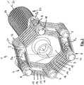
- FIG. 1 shows a torque transmission device 1 with a drive element not shown here, first clamping elements 2, 3, 4, which are evenly spaced in a circumferential direction of the torque transmission device 1, ie 120 ° apart.
- the torque transmission device 1 further has an output element 5, which in turn has three arms 5a, 5b, 5c, on each of which a second clamping element 6, 7, 8 is arranged projecting on one side.
- a first tensioning element 2, 3, 4 is thus arranged in each case between two second clamping elements 6, 7, 8, and vice versa.
- the total of six clamping elements form a uniform hexagon.
- FIG. 1 how out FIG. 1 can be seen, the clamping elements 2, 3, 4 and 6, 7, 8 in the form of rollers or bolts or bushings.
- the coupling elements 12-19 have the shape of oval rings or loops.
- the coupling elements thus each wrap around a partial circumference of approximately 180 ° of the clamping elements 4, 6 or 4, 8.
- the coupling elements can be wholly or at least partially made of glass fiber materials and accordingly also have a certain elasticity in the axial direction 20 of the torque transmission device 1. This means that the first clamping elements 2-4 can shift to some extent relative to the second clamping elements 6, 8, wherein the coupling elements 15-19 deform correspondingly.
- the torque transmission device 1 thus enables both a torque transmission in both directions of rotation.
- the coupling elements 15-19 enable a certain axial displacement of the drive element relative to the output element or vice versa, as well as a certain tilting movement of the drive element relative to the output element 5.
- FIG. 1 can be seen on the example of the first clamping element 2, paragraphs or discs 21, 22 are provided on the front sides of the clamping elements, in particular the Clearspannelements 2, which act as security elements and prevent the associated coupling elements of the sleeve or roller-like first Slip down clamping element 2.
- the clamping elements 2 - 4 or 6 - 8 may be made of hardened steel. As in FIG. 1 can be seen on the basis of the second clamping elements 6 - 8, the clamping elements may be cantilevered, ie be connected only at one of its two end faces with the drive element or the output element 5. In a torque transmission from the drive element to the output element or vice versa, it is therefore to some extent to a deformation or bending of the clamping elements 2-4 and 6-8, whereby a relatively uniform load distribution on the individual clamping elements and the connecting elements ensures them is.
- the pin-like end 23 of the output element 5 is mentioned, which is provided here with a serrated profile 24.
- the pin-like end can z. B. are inserted into a provided with an inner spline tread of a propeller shaft. The serration thus allows a Relatiwerschiebung the output element 5 relative to the propeller shaft.
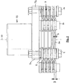
- FIG. 2 shows a plan view of the torque transmitting device of FIG. 1 , It can be clearly seen in this illustration that the coupling elements have a greater width in those sections which wrap around the clamping elements, seen in the direction of the axial direction 20, than in the "free" sections between the individual clamping elements.
- a coupling element 24 in the region of the clamping element 6 has a greater width B than in the region between the clamping element 6 and the clamping element 2, where the width of the coupling element 24 is only b. Due to the smaller width in the region between the adjacent clamping elements is achieved that the coupling elements can bend better and thus better axial relative displacements of the drive element relative to the output element or tilting movements of the drive element relative to the output element, and vice versa, allow.
- FIG. 3 shows an end view of the torque transmitting device 1 seen from the drive element not shown here on the output element 5.
- FIG. 4 shows a cross section through the torque transmission device 1 of FIG. 1 , It can be clearly seen that the clamping elements are sleeve-like clamping elements, which can be seen in particular on the clamping element 8.
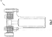
- FIG. 5 shows a further plan view of the torque transmitting device 1, in which case the different widths of the coupling elements in the region of the clamping elements on the one hand and in the region between the clamping elements on the other hand can be seen particularly clearly.
- FIG. 6 shows an embodiment of a coupling element.
- the coupling element shown in side view also has the shape of an oval ring or a loop.
- the coupling element 24 is the FIG. 6 However, not just, but executed in the region between the sections 24a, 24b, which wrap around in the assembled state associated clamping elements, curved.
- the curved central region 24c which by the way also has a smaller width than the "wrap-around sections 24a, 24b", thus enables an even better deformation of the coupling element 24 with an axial displacement or with a tilting of the drive element relative to the output element.
Landscapes
- Engineering & Computer Science (AREA)
- General Engineering & Computer Science (AREA)
- Mechanical Engineering (AREA)
- Motor Power Transmission Devices (AREA)
- Arrangement And Driving Of Transmission Devices (AREA)
Claims (10)
- Véhicule équipé d'un dispositif de transmission de couple (1) permettant d'accoupler l'arbre de sortie de la boîte de vitesses du véhicule avec l'arbre de transmission (5) de celui-ci comprenant :un premier groupe d'éléments de serrage (2-4) qui sont montés solidairement par rapport à l'arbre de sortie de la boîte de vitesses et sont situés à la même distance les uns des autres dans la direction périphérique de l'arbre de sortie de la boîte de vitesses,un second groupe d'éléments de serrage (6, 7, 8) qui sont montés solidairement par rapport à l'arbre de transmission (5) et sont situés à la même distance les uns des autres dans la direction périphérique de l'arbre de transmission (5), véhicule dans lequel la direction périphérique de l'arbre de sortie de la boîte de vitesses ou de l'arbre de transmission, un premier élément de serrage fait respectivement suite à un second élément de serrage et inversement, etdes éléments d'accouplement (15-29, 24), chacun des premiers éléments de serrage (2-4) étant accouplé par l'intermédiaire d'au moins un élément d'accouplement (15-19) avec le second élément de serrage (6-8) le plus proche dans une direction périphérique et par l'intermédiaire d'au moins un élément d'accouplement (15-19) avec le second élément de serrage (6-8) le plus proche dans la direction périphérique opposée,et les éléments d'accouplement (12-19) étant tendus par des éléments de serrage (2-4, 6-8) associés, et les éléments d'accouplement (12-19) entourant en boucle les éléments de serrage (2-4, 6-8) au moins sur une partie de la périphérie de ces éléments (2-4, 6-8), etles éléments d'accouplement étant réalisés en un matériau synthétique renforcé par des fibres,caractérisé en ce queles éléments de serrage (2-4, 6-8) sont réalisés en un matériau qui renferme une matière agissant en tant que lubrifiant ou les éléments de serrage (2-4, 6-8) sont recouverts d'un matériau qui renferme un élément agissant en tant que lubrifiant, ce lubrifiant étant constitué par du polytétrafluoréthylène, du graphite ou du dioxyde de titane.
- Véhicule conforme à la revendication 1,
caractérisé en ce que
chacun des éléments d'accouplement (15-19) accouple un premier élément de serrage (2-4) et un second élément de serrage voisin de celui-ci dans la direction périphérique. - Véhicule conforme à la revendication 1 ou 2,
caractérisé en ce que
sur chacun des éléments de serrage (2-4, 6-8) sont tendus plus de deux éléments d'accouplement (12-19), en particulier plusieurs éléments d'accouplement (12-19). - Véhicule conforme à l'une des revendications 1 à 3,
caractérisé en ce que
les éléments de serrage du premier groupe d'éléments de serrage (2-4) sont accouplés avec les éléments de serrage (6-8) du second groupe d'éléments de serrage uniquement par l'intermédiaire des éléments d'accouplement (12-19). - Véhicule conforme à l'une des revendications 1 à 4,
caractérisé en ce que
les éléments d'accouplement (12-19) sont expansés ou coulés dans un élément d'accouplement élastique reliant les différents éléments d'accouplement. - Véhicule conforme à l'une des revendications 1 à 5,
caractérisé en ce qu'
il est prévu dans la zone d'extrémité frontale des éléments de serrage (2-4, 6-8) un talon ou un disque respectif (21, 22) qui empêche que les éléments d'accouplement glissent sous les éléments de serrage (2-4, 6-8) associés. - Véhicule conforme à l'une des revendications 1 à 6,
caractérisé en ce que
les éléments d'accouplement (12-19) sont réalisés au moins partiellement en fibres de verre. - Véhicule conforme à la revendication 7,
caractérisé en ce que
les éléments d'accouplement sont réalisés en un matériau synthétique renforcé par des fibres de verre. - Véhicule conforme à l'une des revendications 1 à 8,
caractérisé en ce que
les éléments d'accouplement ont la forme de bagues ou de boucles ovales. - Véhicule conforme à l'une des revendications 1 à 9,
caractérisé en ce que
les éléments de serrage ont la forme de galets, de boulons, ou de douilles.
Applications Claiming Priority (1)
| Application Number | Priority Date | Filing Date | Title |
|---|---|---|---|
| DE200810034214 DE102008034214A1 (de) | 2008-07-23 | 2008-07-23 | Drehmomentübertragungseinrichtung |
Publications (2)
| Publication Number | Publication Date |
|---|---|
| EP2148106A1 EP2148106A1 (fr) | 2010-01-27 |
| EP2148106B1 true EP2148106B1 (fr) | 2017-03-01 |
Family
ID=41228281
Family Applications (1)
| Application Number | Title | Priority Date | Filing Date |
|---|---|---|---|
| EP09008019.3A Active EP2148106B1 (fr) | 2008-07-23 | 2009-06-19 | Dispositif de transmission de couple |
Country Status (2)
| Country | Link |
|---|---|
| EP (1) | EP2148106B1 (fr) |
| DE (1) | DE102008034214A1 (fr) |
Families Citing this family (5)
| Publication number | Priority date | Publication date | Assignee | Title |
|---|---|---|---|---|
| DE102009009683A1 (de) | 2009-02-19 | 2010-08-26 | Bayerische Motoren Werke Aktiengesellschaft | Drehmomentübertragungseinrichtung insbesondere für Automobile und Motorräder |
| DE102009038039A1 (de) | 2009-08-19 | 2011-02-24 | Bayerische Motoren Werke Aktiengesellschaft | Drehmomentübertragungseinrichtung |
| CN103032478A (zh) * | 2013-01-21 | 2013-04-10 | 吴实渊 | 一种空间柔性联轴器 |
| DE102014114460A1 (de) | 2014-10-06 | 2016-04-07 | xperion components GmbH & Co. KG | Anordnung für eine Wellenkupplung |
| DE102016221754A1 (de) * | 2016-11-07 | 2018-05-09 | Zf Friedrichshafen Ag | Lasche mit Koppelelement für eine elastische Kupplung |
Citations (1)
| Publication number | Priority date | Publication date | Assignee | Title |
|---|---|---|---|---|
| US6203434B1 (en) * | 1997-05-17 | 2001-03-20 | Daimlerchrysler Ag | Cardan-type joint including supportive compression bars |
Family Cites Families (13)
| Publication number | Priority date | Publication date | Assignee | Title |
|---|---|---|---|---|
| DE182230C (fr) | ||||
| US1466238A (en) | 1920-04-22 | 1923-08-28 | Snead & Co Iron Works | Flexible joint |
| GB321999A (en) * | 1928-08-29 | 1929-11-28 | Christian Hamilton Gray | Improvements in or relating to universal joints |
| JPH0752427Y2 (ja) * | 1986-11-07 | 1995-11-29 | 東洋ゴム工業株式会社 | 高負荷トルク伝達用弾性継手 |
| US5033988A (en) * | 1989-03-07 | 1991-07-23 | Lord Corporation | Reversible endless belt rotary coupling |
| US5163876A (en) | 1990-07-30 | 1992-11-17 | Kop-Flex, Inc. | Method of constructing a composite flexible coupling element |
| DE4304274C1 (de) * | 1993-02-12 | 1994-03-17 | Sgf Gmbh & Co Kg | Gelenkscheibe, insbesondere für den Antriebsstrang in Kraftfahrzeugen |
| DE4437989C2 (de) | 1994-10-24 | 1996-11-14 | Sgf Gmbh & Co Kg | Verfahren zum Herstellen von Gelenkscheiben |
| DE19934469C2 (de) | 1999-07-27 | 2003-08-07 | Atec Weiss Gmbh & Co Kg | Flexible Wellenkupplung mit durch gummielastischem Material verbundenen, zueinander axial beabstandeten Lamellen |
| DE60124763T2 (de) * | 2000-12-20 | 2007-09-13 | Nok-Vibracoustic Co., Ltd. | Elastische verbindungsvorrichtung |
| JP3680780B2 (ja) * | 2001-10-11 | 2005-08-10 | 東洋ゴム工業株式会社 | 弾性継手 |
| WO2004098908A1 (fr) | 2003-05-09 | 2004-11-18 | Koyo Seiko Co., Ltd. | Palier de poussee excentrique et roue integrant une suspension faisant appel a ce palier de poussee |
| EP1818556B1 (fr) | 2006-02-10 | 2008-09-03 | Wulf Gaertner Autoparts AG | Méthode de fabrication d'un unité d'enroulement |
-
2008
- 2008-07-23 DE DE200810034214 patent/DE102008034214A1/de not_active Ceased
-
2009
- 2009-06-19 EP EP09008019.3A patent/EP2148106B1/fr active Active
Patent Citations (1)
| Publication number | Priority date | Publication date | Assignee | Title |
|---|---|---|---|---|
| US6203434B1 (en) * | 1997-05-17 | 2001-03-20 | Daimlerchrysler Ag | Cardan-type joint including supportive compression bars |
Also Published As
| Publication number | Publication date |
|---|---|
| EP2148106A1 (fr) | 2010-01-27 |
| DE102008034214A1 (de) | 2010-01-28 |
Similar Documents
| Publication | Publication Date | Title |
|---|---|---|
| DE102009020906B4 (de) | Verbindungsvorrichtung | |
| DE3132877A1 (de) | Kupplung | |
| DE102008028396A1 (de) | Verbindungsanordnung und Gelenkwelle hiermit | |
| EP2148106A1 (fr) | Dispositif de transmission de couple | |
| WO2007090890A1 (fr) | Procédé de fabrication d'une unité à boucles | |
| DE60206553T2 (de) | CVT-Kettenriemen mit an Kettenlaschen auf oder zwischen Bolzenenden angebrachten Verschleisskissen | |
| DE2708538C3 (de) | Verbindung zwischen den Kettengliedern einer Gleiskette | |
| EP1819939B1 (fr) | Chaine articulee destinee notamment a une transmission de vehicule | |
| DE3514124A1 (de) | Kardanische doppelkupplung | |
| DE102009009683A1 (de) | Drehmomentübertragungseinrichtung insbesondere für Automobile und Motorräder | |
| EP0878633A2 (fr) | Accouplement d'arbres | |
| EP1001182B1 (fr) | Ensemble de joint universel pour un arbre articulé | |
| EP1019642B1 (fr) | Articulation pour joints articules appropries a la transmission de couple | |
| EP2467609B1 (fr) | Dispositif de transmission de couple | |
| EP1691095B1 (fr) | Isolement axial pour un croissillon d'un joint universel | |
| EP1382870B1 (fr) | Accouplement élastique | |
| DE102018106131A1 (de) | Umschlingungsmittel und CVT-Getriebe mit selbigem | |
| EP3274604B1 (fr) | Accouplement compensateur élastique comprenant des moyeux s'imbriquant les uns dans les autres par complémentarité de forme | |
| EP0534899A1 (fr) | Entraînement pour un train de roues d'un engin de traction ferroviaire et élément de ressort pour tel entraînement | |
| AT528294B1 (de) | Kupplungsvorrichtung mit Polygonschaft | |
| EP1530685B1 (fr) | Element de raccordement pour relier des broches articulees a des unites de raccordement, notamment fixation d'assemblage a centrage conique | |
| DE20014606U1 (de) | Steckbare, drehelastische Wellenkupplung | |
| EP2163776B1 (fr) | Arbre de transmission pour véhicules | |
| WO2006058528A1 (fr) | Chaine articulee destinee notamment a une transmission de vehicule | |
| DE3415908A1 (de) | Klauenkupplung |
Legal Events
| Date | Code | Title | Description |
|---|---|---|---|
| PUAI | Public reference made under article 153(3) epc to a published international application that has entered the european phase |
Free format text: ORIGINAL CODE: 0009012 |
|
| AK | Designated contracting states |
Kind code of ref document: A1 Designated state(s): AT BE BG CH CY CZ DE DK EE ES FI FR GB GR HR HU IE IS IT LI LT LU LV MC MK MT NL NO PL PT RO SE SI SK TR |
|
| AX | Request for extension of the european patent |
Extension state: AL BA RS |
|
| 17P | Request for examination filed |
Effective date: 20100211 |
|
| 17Q | First examination report despatched |
Effective date: 20100310 |
|
| RIN1 | Information on inventor provided before grant (corrected) |
Inventor name: TICHELMANN, PATRICK Inventor name: HAHN, WOLFGANG Inventor name: FRANKE, OLIVER Inventor name: KORNPROBST, WOLFGANG Inventor name: SCHUERMANN, HELMUT Inventor name: DULLENKOPF, DIRK |
|
| GRAP | Despatch of communication of intention to grant a patent |
Free format text: ORIGINAL CODE: EPIDOSNIGR1 |
|
| INTG | Intention to grant announced |
Effective date: 20160929 |
|
| GRAS | Grant fee paid |
Free format text: ORIGINAL CODE: EPIDOSNIGR3 |
|
| GRAA | (expected) grant |
Free format text: ORIGINAL CODE: 0009210 |
|
| AK | Designated contracting states |
Kind code of ref document: B1 Designated state(s): AT BE BG CH CY CZ DE DK EE ES FI FR GB GR HR HU IE IS IT LI LT LU LV MC MK MT NL NO PL PT RO SE SI SK TR |
|
| REG | Reference to a national code |
Ref country code: GB Ref legal event code: FG4D Free format text: NOT ENGLISH |
|
| RIN1 | Information on inventor provided before grant (corrected) |
Inventor name: TICHELMANN, PATRICK Inventor name: KORNPROBST, WOLFGANG Inventor name: SCHUERMANN, HELMUT Inventor name: DULLENKOPF, DIRK Inventor name: FRANKE, OLIVER Inventor name: HAHN, WOLFGANG |
|
| REG | Reference to a national code |
Ref country code: CH Ref legal event code: EP Ref country code: AT Ref legal event code: REF Ref document number: 871747 Country of ref document: AT Kind code of ref document: T Effective date: 20170315 |
|
| REG | Reference to a national code |
Ref country code: IE Ref legal event code: FG4D Free format text: LANGUAGE OF EP DOCUMENT: GERMAN |
|
| REG | Reference to a national code |
Ref country code: DE Ref legal event code: R096 Ref document number: 502009013684 Country of ref document: DE |
|
| REG | Reference to a national code |
Ref country code: FR Ref legal event code: PLFP Year of fee payment: 9 |
|
| REG | Reference to a national code |
Ref country code: NL Ref legal event code: MP Effective date: 20170301 |
|
| REG | Reference to a national code |
Ref country code: LT Ref legal event code: MG4D |
|
| PG25 | Lapsed in a contracting state [announced via postgrant information from national office to epo] |
Ref country code: LT Free format text: LAPSE BECAUSE OF FAILURE TO SUBMIT A TRANSLATION OF THE DESCRIPTION OR TO PAY THE FEE WITHIN THE PRESCRIBED TIME-LIMIT Effective date: 20170301 Ref country code: NO Free format text: LAPSE BECAUSE OF FAILURE TO SUBMIT A TRANSLATION OF THE DESCRIPTION OR TO PAY THE FEE WITHIN THE PRESCRIBED TIME-LIMIT Effective date: 20170601 Ref country code: GR Free format text: LAPSE BECAUSE OF FAILURE TO SUBMIT A TRANSLATION OF THE DESCRIPTION OR TO PAY THE FEE WITHIN THE PRESCRIBED TIME-LIMIT Effective date: 20170602 Ref country code: FI Free format text: LAPSE BECAUSE OF FAILURE TO SUBMIT A TRANSLATION OF THE DESCRIPTION OR TO PAY THE FEE WITHIN THE PRESCRIBED TIME-LIMIT Effective date: 20170301 Ref country code: HR Free format text: LAPSE BECAUSE OF FAILURE TO SUBMIT A TRANSLATION OF THE DESCRIPTION OR TO PAY THE FEE WITHIN THE PRESCRIBED TIME-LIMIT Effective date: 20170301 |
|
| PG25 | Lapsed in a contracting state [announced via postgrant information from national office to epo] |
Ref country code: LV Free format text: LAPSE BECAUSE OF FAILURE TO SUBMIT A TRANSLATION OF THE DESCRIPTION OR TO PAY THE FEE WITHIN THE PRESCRIBED TIME-LIMIT Effective date: 20170301 Ref country code: ES Free format text: LAPSE BECAUSE OF FAILURE TO SUBMIT A TRANSLATION OF THE DESCRIPTION OR TO PAY THE FEE WITHIN THE PRESCRIBED TIME-LIMIT Effective date: 20170301 Ref country code: BG Free format text: LAPSE BECAUSE OF FAILURE TO SUBMIT A TRANSLATION OF THE DESCRIPTION OR TO PAY THE FEE WITHIN THE PRESCRIBED TIME-LIMIT Effective date: 20170601 Ref country code: SE Free format text: LAPSE BECAUSE OF FAILURE TO SUBMIT A TRANSLATION OF THE DESCRIPTION OR TO PAY THE FEE WITHIN THE PRESCRIBED TIME-LIMIT Effective date: 20170301 |
|
| PG25 | Lapsed in a contracting state [announced via postgrant information from national office to epo] |
Ref country code: NL Free format text: LAPSE BECAUSE OF FAILURE TO SUBMIT A TRANSLATION OF THE DESCRIPTION OR TO PAY THE FEE WITHIN THE PRESCRIBED TIME-LIMIT Effective date: 20170301 |
|
| PG25 | Lapsed in a contracting state [announced via postgrant information from national office to epo] |
Ref country code: CZ Free format text: LAPSE BECAUSE OF FAILURE TO SUBMIT A TRANSLATION OF THE DESCRIPTION OR TO PAY THE FEE WITHIN THE PRESCRIBED TIME-LIMIT Effective date: 20170301 Ref country code: SK Free format text: LAPSE BECAUSE OF FAILURE TO SUBMIT A TRANSLATION OF THE DESCRIPTION OR TO PAY THE FEE WITHIN THE PRESCRIBED TIME-LIMIT Effective date: 20170301 Ref country code: RO Free format text: LAPSE BECAUSE OF FAILURE TO SUBMIT A TRANSLATION OF THE DESCRIPTION OR TO PAY THE FEE WITHIN THE PRESCRIBED TIME-LIMIT Effective date: 20170301 Ref country code: EE Free format text: LAPSE BECAUSE OF FAILURE TO SUBMIT A TRANSLATION OF THE DESCRIPTION OR TO PAY THE FEE WITHIN THE PRESCRIBED TIME-LIMIT Effective date: 20170301 |
|
| PG25 | Lapsed in a contracting state [announced via postgrant information from national office to epo] |
Ref country code: PT Free format text: LAPSE BECAUSE OF FAILURE TO SUBMIT A TRANSLATION OF THE DESCRIPTION OR TO PAY THE FEE WITHIN THE PRESCRIBED TIME-LIMIT Effective date: 20170703 Ref country code: IS Free format text: LAPSE BECAUSE OF FAILURE TO SUBMIT A TRANSLATION OF THE DESCRIPTION OR TO PAY THE FEE WITHIN THE PRESCRIBED TIME-LIMIT Effective date: 20170701 Ref country code: PL Free format text: LAPSE BECAUSE OF FAILURE TO SUBMIT A TRANSLATION OF THE DESCRIPTION OR TO PAY THE FEE WITHIN THE PRESCRIBED TIME-LIMIT Effective date: 20170301 |
|
| REG | Reference to a national code |
Ref country code: DE Ref legal event code: R097 Ref document number: 502009013684 Country of ref document: DE |
|
| PLBE | No opposition filed within time limit |
Free format text: ORIGINAL CODE: 0009261 |
|
| STAA | Information on the status of an ep patent application or granted ep patent |
Free format text: STATUS: NO OPPOSITION FILED WITHIN TIME LIMIT |
|
| PG25 | Lapsed in a contracting state [announced via postgrant information from national office to epo] |
Ref country code: DK Free format text: LAPSE BECAUSE OF FAILURE TO SUBMIT A TRANSLATION OF THE DESCRIPTION OR TO PAY THE FEE WITHIN THE PRESCRIBED TIME-LIMIT Effective date: 20170301 Ref country code: MC Free format text: LAPSE BECAUSE OF FAILURE TO SUBMIT A TRANSLATION OF THE DESCRIPTION OR TO PAY THE FEE WITHIN THE PRESCRIBED TIME-LIMIT Effective date: 20170301 |
|
| REG | Reference to a national code |
Ref country code: CH Ref legal event code: PL |
|
| 26N | No opposition filed |
Effective date: 20171204 |
|
| PG25 | Lapsed in a contracting state [announced via postgrant information from national office to epo] |
Ref country code: SI Free format text: LAPSE BECAUSE OF FAILURE TO SUBMIT A TRANSLATION OF THE DESCRIPTION OR TO PAY THE FEE WITHIN THE PRESCRIBED TIME-LIMIT Effective date: 20170301 |
|
| REG | Reference to a national code |
Ref country code: IE Ref legal event code: MM4A |
|
| PG25 | Lapsed in a contracting state [announced via postgrant information from national office to epo] |
Ref country code: LU Free format text: LAPSE BECAUSE OF NON-PAYMENT OF DUE FEES Effective date: 20170619 Ref country code: IE Free format text: LAPSE BECAUSE OF NON-PAYMENT OF DUE FEES Effective date: 20170619 Ref country code: LI Free format text: LAPSE BECAUSE OF NON-PAYMENT OF DUE FEES Effective date: 20170630 Ref country code: CH Free format text: LAPSE BECAUSE OF NON-PAYMENT OF DUE FEES Effective date: 20170630 |
|
| REG | Reference to a national code |
Ref country code: BE Ref legal event code: MM Effective date: 20170630 |
|
| REG | Reference to a national code |
Ref country code: FR Ref legal event code: PLFP Year of fee payment: 10 |
|
| REG | Reference to a national code |
Ref country code: AT Ref legal event code: MM01 Ref document number: 871747 Country of ref document: AT Kind code of ref document: T Effective date: 20170619 |
|
| PG25 | Lapsed in a contracting state [announced via postgrant information from national office to epo] |
Ref country code: BE Free format text: LAPSE BECAUSE OF NON-PAYMENT OF DUE FEES Effective date: 20170630 |
|
| PG25 | Lapsed in a contracting state [announced via postgrant information from national office to epo] |
Ref country code: MT Free format text: LAPSE BECAUSE OF FAILURE TO SUBMIT A TRANSLATION OF THE DESCRIPTION OR TO PAY THE FEE WITHIN THE PRESCRIBED TIME-LIMIT Effective date: 20170301 |
|
| PG25 | Lapsed in a contracting state [announced via postgrant information from national office to epo] |
Ref country code: AT Free format text: LAPSE BECAUSE OF NON-PAYMENT OF DUE FEES Effective date: 20170619 |
|
| PG25 | Lapsed in a contracting state [announced via postgrant information from national office to epo] |
Ref country code: HU Free format text: LAPSE BECAUSE OF FAILURE TO SUBMIT A TRANSLATION OF THE DESCRIPTION OR TO PAY THE FEE WITHIN THE PRESCRIBED TIME-LIMIT; INVALID AB INITIO Effective date: 20090619 |
|
| PG25 | Lapsed in a contracting state [announced via postgrant information from national office to epo] |
Ref country code: CY Free format text: LAPSE BECAUSE OF NON-PAYMENT OF DUE FEES Effective date: 20170301 |
|
| PG25 | Lapsed in a contracting state [announced via postgrant information from national office to epo] |
Ref country code: MK Free format text: LAPSE BECAUSE OF FAILURE TO SUBMIT A TRANSLATION OF THE DESCRIPTION OR TO PAY THE FEE WITHIN THE PRESCRIBED TIME-LIMIT Effective date: 20170301 |
|
| PG25 | Lapsed in a contracting state [announced via postgrant information from national office to epo] |
Ref country code: TR Free format text: LAPSE BECAUSE OF FAILURE TO SUBMIT A TRANSLATION OF THE DESCRIPTION OR TO PAY THE FEE WITHIN THE PRESCRIBED TIME-LIMIT Effective date: 20170301 |
|
| P01 | Opt-out of the competence of the unified patent court (upc) registered |
Effective date: 20230502 |
|
| PGFP | Annual fee paid to national office [announced via postgrant information from national office to epo] |
Ref country code: DE Payment date: 20250605 Year of fee payment: 17 |
|
| PGFP | Annual fee paid to national office [announced via postgrant information from national office to epo] |
Ref country code: GB Payment date: 20250620 Year of fee payment: 17 |
|
| PGFP | Annual fee paid to national office [announced via postgrant information from national office to epo] |
Ref country code: FR Payment date: 20250618 Year of fee payment: 17 |
|
| PGFP | Annual fee paid to national office [announced via postgrant information from national office to epo] |
Ref country code: IT Payment date: 20250630 Year of fee payment: 17 |