EP2148125A1 - Verbundisolierungsstruktur zur Isolierung der inneren Oberfläche von ringförmigen Kanälen - Google Patents
Verbundisolierungsstruktur zur Isolierung der inneren Oberfläche von ringförmigen Kanälen Download PDFInfo
- Publication number
- EP2148125A1 EP2148125A1 EP08015316A EP08015316A EP2148125A1 EP 2148125 A1 EP2148125 A1 EP 2148125A1 EP 08015316 A EP08015316 A EP 08015316A EP 08015316 A EP08015316 A EP 08015316A EP 2148125 A1 EP2148125 A1 EP 2148125A1
- Authority
- EP
- European Patent Office
- Prior art keywords
- insulation
- duct
- layer
- duct insulation
- composite
- Prior art date
- Legal status (The legal status is an assumption and is not a legal conclusion. Google has not performed a legal analysis and makes no representation as to the accuracy of the status listed.)
- Withdrawn
Links
- 238000009413 insulation Methods 0.000 title claims abstract description 93
- 239000002131 composite material Substances 0.000 title claims abstract description 43
- 239000000853 adhesive Substances 0.000 claims abstract description 25
- 230000001070 adhesive effect Effects 0.000 claims abstract description 25
- 239000006260 foam Substances 0.000 claims description 16
- -1 polypropylene Polymers 0.000 claims description 10
- 239000000835 fiber Substances 0.000 claims description 9
- 239000006263 elastomeric foam Substances 0.000 claims description 7
- 239000012774 insulation material Substances 0.000 claims description 7
- 229910052751 metal Inorganic materials 0.000 claims description 7
- 239000002184 metal Substances 0.000 claims description 7
- 229920001169 thermoplastic Polymers 0.000 claims description 7
- 239000004416 thermosoftening plastic Substances 0.000 claims description 7
- 239000005062 Polybutadiene Substances 0.000 claims description 6
- 239000002174 Styrene-butadiene Substances 0.000 claims description 6
- 229920003020 cross-linked polyethylene Polymers 0.000 claims description 6
- 239000004703 cross-linked polyethylene Substances 0.000 claims description 6
- 229920000915 polyvinyl chloride Polymers 0.000 claims description 6
- 239000004800 polyvinyl chloride Substances 0.000 claims description 6
- 229920003048 styrene butadiene rubber Polymers 0.000 claims description 6
- 239000011152 fibreglass Substances 0.000 claims description 5
- 229920000642 polymer Polymers 0.000 claims description 5
- 244000043261 Hevea brasiliensis Species 0.000 claims description 4
- 239000004743 Polypropylene Substances 0.000 claims description 4
- MTAZNLWOLGHBHU-UHFFFAOYSA-N butadiene-styrene rubber Chemical compound C=CC=C.C=CC1=CC=CC=C1 MTAZNLWOLGHBHU-UHFFFAOYSA-N 0.000 claims description 4
- YACLQRRMGMJLJV-UHFFFAOYSA-N chloroprene Chemical compound ClC(=C)C=C YACLQRRMGMJLJV-UHFFFAOYSA-N 0.000 claims description 4
- 239000000463 material Substances 0.000 claims description 4
- 150000002739 metals Chemical class 0.000 claims description 4
- 239000000203 mixture Substances 0.000 claims description 4
- 229920003052 natural elastomer Polymers 0.000 claims description 4
- 229920001194 natural rubber Polymers 0.000 claims description 4
- 150000002825 nitriles Chemical class 0.000 claims description 4
- 229920002857 polybutadiene Polymers 0.000 claims description 4
- 229920000139 polyethylene terephthalate Polymers 0.000 claims description 4
- 239000005020 polyethylene terephthalate Substances 0.000 claims description 4
- 229920001155 polypropylene Polymers 0.000 claims description 4
- 229920002635 polyurethane Polymers 0.000 claims description 4
- 239000004814 polyurethane Substances 0.000 claims description 4
- 239000011115 styrene butadiene Substances 0.000 claims description 4
- 229920001971 elastomer Polymers 0.000 claims description 3
- 229920000742 Cotton Polymers 0.000 claims description 2
- 229920002943 EPDM rubber Polymers 0.000 claims description 2
- ATJFFYVFTNAWJD-UHFFFAOYSA-N Tin Chemical compound [Sn] ATJFFYVFTNAWJD-UHFFFAOYSA-N 0.000 claims description 2
- 229910052782 aluminium Inorganic materials 0.000 claims description 2
- XAGFODPZIPBFFR-UHFFFAOYSA-N aluminium Chemical compound [Al] XAGFODPZIPBFFR-UHFFFAOYSA-N 0.000 claims description 2
- 229920005557 bromobutyl Polymers 0.000 claims description 2
- 125000000484 butyl group Chemical group [H]C([*])([H])C([H])([H])C([H])([H])C([H])([H])[H] 0.000 claims description 2
- 229920005549 butyl rubber Polymers 0.000 claims description 2
- 229920005556 chlorobutyl Polymers 0.000 claims description 2
- HQQADJVZYDDRJT-UHFFFAOYSA-N ethene;prop-1-ene Chemical group C=C.CC=C HQQADJVZYDDRJT-UHFFFAOYSA-N 0.000 claims description 2
- 229920005555 halobutyl Polymers 0.000 claims description 2
- 125000004968 halobutyl group Chemical group 0.000 claims description 2
- 229920000728 polyester Polymers 0.000 claims description 2
- 229920001296 polysiloxane Polymers 0.000 claims description 2
- 229920005989 resin Polymers 0.000 claims description 2
- 239000011347 resin Substances 0.000 claims description 2
- 239000005060 rubber Substances 0.000 claims description 2
- 229910052718 tin Inorganic materials 0.000 claims description 2
- 229910000831 Steel Inorganic materials 0.000 claims 1
- 239000010959 steel Substances 0.000 claims 1
- 239000004820 Pressure-sensitive adhesive Substances 0.000 description 5
- 238000005520 cutting process Methods 0.000 description 5
- 238000000034 method Methods 0.000 description 4
- 239000004821 Contact adhesive Substances 0.000 description 3
- 239000004215 Carbon black (E152) Substances 0.000 description 2
- 239000000383 hazardous chemical Substances 0.000 description 2
- 231100000206 health hazard Toxicity 0.000 description 2
- 239000012943 hotmelt Substances 0.000 description 2
- 229930195733 hydrocarbon Natural products 0.000 description 2
- 238000009434 installation Methods 0.000 description 2
- 238000004519 manufacturing process Methods 0.000 description 2
- 238000005096 rolling process Methods 0.000 description 2
- 239000002904 solvent Substances 0.000 description 2
- XLYOFNOQVPJJNP-UHFFFAOYSA-N water Substances O XLYOFNOQVPJJNP-UHFFFAOYSA-N 0.000 description 2
- 229910001335 Galvanized steel Inorganic materials 0.000 description 1
- 230000004888 barrier function Effects 0.000 description 1
- 238000000576 coating method Methods 0.000 description 1
- 230000006835 compression Effects 0.000 description 1
- 238000007906 compression Methods 0.000 description 1
- 230000003247 decreasing effect Effects 0.000 description 1
- 230000001419 dependent effect Effects 0.000 description 1
- 239000000806 elastomer Substances 0.000 description 1
- 239000008397 galvanized steel Substances 0.000 description 1
- 230000005484 gravity Effects 0.000 description 1
- 231100001261 hazardous Toxicity 0.000 description 1
- 238000003780 insertion Methods 0.000 description 1
- 230000037431 insertion Effects 0.000 description 1
- 239000011810 insulating material Substances 0.000 description 1
- 230000000135 prohibitive effect Effects 0.000 description 1
- 239000007787 solid Substances 0.000 description 1
Images
Classifications
-
- F—MECHANICAL ENGINEERING; LIGHTING; HEATING; WEAPONS; BLASTING
- F16—ENGINEERING ELEMENTS AND UNITS; GENERAL MEASURES FOR PRODUCING AND MAINTAINING EFFECTIVE FUNCTIONING OF MACHINES OR INSTALLATIONS; THERMAL INSULATION IN GENERAL
- F16L—PIPES; JOINTS OR FITTINGS FOR PIPES; SUPPORTS FOR PIPES, CABLES OR PROTECTIVE TUBING; MEANS FOR THERMAL INSULATION IN GENERAL
- F16L59/00—Thermal insulation in general
- F16L59/02—Shape or form of insulating materials, with or without coverings integral with the insulating materials
- F16L59/021—Shape or form of insulating materials, with or without coverings integral with the insulating materials comprising a single piece or sleeve, e.g. split sleeves; consisting of two half sleeves; comprising more than two segments
-
- F—MECHANICAL ENGINEERING; LIGHTING; HEATING; WEAPONS; BLASTING
- F16—ENGINEERING ELEMENTS AND UNITS; GENERAL MEASURES FOR PRODUCING AND MAINTAINING EFFECTIVE FUNCTIONING OF MACHINES OR INSTALLATIONS; THERMAL INSULATION IN GENERAL
- F16L—PIPES; JOINTS OR FITTINGS FOR PIPES; SUPPORTS FOR PIPES, CABLES OR PROTECTIVE TUBING; MEANS FOR THERMAL INSULATION IN GENERAL
- F16L59/00—Thermal insulation in general
- F16L59/14—Arrangements for the insulation of pipes or pipe systems
- F16L59/147—Arrangements for the insulation of pipes or pipe systems the insulation being located inwardly of the outer surface of the pipe
-
- F—MECHANICAL ENGINEERING; LIGHTING; HEATING; WEAPONS; BLASTING
- F16—ENGINEERING ELEMENTS AND UNITS; GENERAL MEASURES FOR PRODUCING AND MAINTAINING EFFECTIVE FUNCTIONING OF MACHINES OR INSTALLATIONS; THERMAL INSULATION IN GENERAL
- F16L—PIPES; JOINTS OR FITTINGS FOR PIPES; SUPPORTS FOR PIPES, CABLES OR PROTECTIVE TUBING; MEANS FOR THERMAL INSULATION IN GENERAL
- F16L9/00—Rigid pipes
- F16L9/21—Rigid pipes made of sound-absorbing materials or with sound-absorbing structure
-
- Y—GENERAL TAGGING OF NEW TECHNOLOGICAL DEVELOPMENTS; GENERAL TAGGING OF CROSS-SECTIONAL TECHNOLOGIES SPANNING OVER SEVERAL SECTIONS OF THE IPC; TECHNICAL SUBJECTS COVERED BY FORMER USPC CROSS-REFERENCE ART COLLECTIONS [XRACs] AND DIGESTS
- Y10—TECHNICAL SUBJECTS COVERED BY FORMER USPC
- Y10T—TECHNICAL SUBJECTS COVERED BY FORMER US CLASSIFICATION
- Y10T428/00—Stock material or miscellaneous articles
- Y10T428/13—Hollow or container type article [e.g., tube, vase, etc.]
- Y10T428/1352—Polymer or resin containing [i.e., natural or synthetic]
- Y10T428/139—Open-ended, self-supporting conduit, cylinder, or tube-type article
- Y10T428/1393—Multilayer [continuous layer]
Definitions
- This invention relates to insulation structures and methods for the insulation of interior surfaces of annular ducts.
- annular duct shell (2) low density fiber, such as fiberglass, and (3) annular (perforated or solid) insulated retaining insert.
- the purpose of the retaining insert is to hold the insulation material against the interior wall of the annular duct. Fiberglass insulation materials do not have sufficient structural integrity to maintain an unaided annular shape, and cannot be installed in annular ducts without the use of strong adhesives, mechanical fasteners and/or annular retaining inserts. The use of limited open time contact adhesives is prohibitive due to health hazards and surface area application limits associated with short setup time.
- the installation of metal retaining inserts is costly, requires special safety equipment and practices, reduces the NRC (noise reduction coefficient) of the installed insulation, and increases the installed weight of the duct sections by 1/3 or greater.
- a flexible, composite duct insulation comprises a first layer forming an insulation layer, and a second layer forming a structural support layer.
- the first layer is adhered to the second layer by an adhesive.
- the composite duct insulation structure has sufficient strength and radially outward-directed spring force to press and hold the composite duct insulation outwardly against an inner annular surface wall of a tubular duct without additional spring structure or retaining structure.
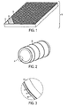
- FIG. 1 is a perspective view of one embodiment showing layers of a composite insulation system.
- FIG. 2 is a perspective end view of one embodiment showing the configuration of the composite insulation system in a substantially annular duct
- FIG. 3 is a detailed cross-sectional view of section A of the end view of FIG. 2 .
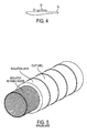
- FIG. 4 is a schematic view of one embodiment showing adhesive strips.
- FIG. 5 is a perspective expanded end view of prior annular duct insulation systems.
- the present invention provides a composite insulation structure that improves the NRC characteristics of the installed insulation structure, reduces or eliminates safety and health hazards associated with current insulation installation practices, and reduces the duct section weight compared to prior art insulation structures.
- a low-density annular duct insulation system comprises a layered composite structure that can be formed into an annular configuration and easily installed and held securely in place to the interior wall of an annular duct, through radially outward-directed force of the insulation structure alone.
- the present invention forms an effective vapor barrier.
- the composite insulation can also be fixed in place using non-hazardous, peel and seal pressure-sensitive adhesive fasteners.
- the mechanical structure of the composite insulation system can be easily cut to meet the dimensional requirements of a wide range of duct shapes and sizes.
- the composite can be cut without special cutting tools.
- the present invention provides a composite duct insulation comprising of an insulation layer and a structural support layer.
- the first layer is adhered to the second layer by an adhesive to form a composite structure.
- This composite insulation structure has sufficient strength and radially outward-directed spring force to press the composite duct insulation outwardly against an inner annular surface wall of a tubular duct (e.g., a substantially horizontal tubular duct) without additional spring structure or retaining structure.
- the spring force required to prevent the composite insulation sleeve structure from collapsing on itself is that required to overcome gravity. This is dependent on the density and thickness of the composite being used and the diameter of the duct being insulated, and can easily be determined by persons skilled in the art. The actual force will change depending on the cut length of the composite piece being formed to an annular shape and inserted into the duct shell. Due to the compression characteristics of various composites, with certain composites, cut pieces of a length greater than the duct circumference may be installed, in which case the applied force is determined by cut length of the piece being installed. In preferred embodiments, the installed foam insulation composite retains its' annular shape without the necessity of cutting lengths greater than the minimum specified manufacturing circumference of the receiving duct shell.
- the composite insulation structure 10 of the invention comprises a first outer layer 12 of insulation material and a second inner layer 14 providing structural support.
- the first layer 12 is adhered to the second layer by an adhesive 16.
- the insulation layer 12 can be formed from any material suitable for insulating ducts, preferably elastomeric foams, thermoplastic foams, thermo-set polymer foams, and fiber insulation materials.
- Open- or closed-cell type elastomeric foams, and preferably cross-linked foams are used for the insulation layer 12.
- Any suitable elastomeric foam materials can be used, including but not limited to, Ethylene-propylene (EPDM), Nitrile (NBR), Styrene-butadiene (SBR), Polybutadiene (BR), Natural rubber (NR), Chloroprene (CR), Butyl and Halobutyl (IIR, BIIR, CIIR), Silicone (MQ), Blends with compatible rubbers, e.g. Styrene-butadiene and polybutadiene, Blends with compatible resins, e.g., Nitrile and polyvinyl chloride.
- the insulation layer 12 is formed from a thermoplastic foam, preferably cross-linked polyethylene, non-cross-linked polyethylene, polypropylene, polyvinylchloride, polyethylene terephthalate, or polyurethane.
- the insulation layer 12 may be formed from fiber insulation material, preferably fiberglass, organic fibers, or a combination thereof.
- the insulation layer 12 may be formed from an organic fiber, preferably cotton, polyester, or a combination thereof.
- the insulation layer thickness may be from about 0.05 inch to 5 inches, preferably about 0.5 inch to 3 inches.
- the structural support layer 14 is preferably a spring-flex support layer and is formed from thermo plastic foams, thermo-set polymer foams, or corrugated metals, or other sheet metals that demonstrate radially outward-directed spring force.
- the structural support layer 14 is formed from a thermo plastic foam, preferably cross-linked or non-cross linked polyethylene, polypropylene, polyvinylchloride, polyethylene terephthalate, or polyurethane.
- the structural support layer 14 is formed from a corrugated metal, preferably aluminum, galvanized steel, or tin.
- the support layer thickness may be from about 0.02 inch to 1 inch, preferably about 0.05 inch to 0.375 inch.
- the insulation layer 12 is bound to at least the inner structural support layer using any suitable adhesive 16 for adhering insulating materials.
- the adhesive 16 is contact- or pressure-sensitive adhesive, more preferably hotmelt pressure sensitive adhesive.
- the adhesive 16 may be acrylic hydrocarbon solvent-based or water-based.
- the adhesive thickness may be from about 0.001 inch to 0.075 inch, preferably about 0.002 inch to 0.015 inch.
- the composite duct insulation structure has sufficient strength and radially outward-directed spring force to press the composite duct insulation structure 10 outwardly against an inner annular surface wall of a tubular duct 18 without additional spring structure or retaining structure.
- the composite duct insulation structure 10 can be positioned within an annular duct 18 as shown in FIG. 2 .
- the insulation is secured to the interior wall of a duct by radially outward-directed spring force which can be increased or decreased by altering the circumference of the composite insulation structure 10.
- This invention eliminates the need to inventory multiple sizes of rigid pre-formed insulation or fabricated metal insulation retaining inserts.
- the present invention can be easily cut to size in any location, it can be used to insulate any size duct without manufacturing custom sized structural inserts or pre-formed insulation, and without the use of specialized cutting tools.
- the insulation layer 12 is oriented inwardly toward the center of an annular duct, and the structural support layer 14 is oriented outwardly toward the inner annular surface wall of tubular duct 18.
- insulation layer 12 is oriented outwardly toward the inner annular surface wall of a tubular duct 18, and the structural support layer 14 is oriented inwardly toward the center of duct 18.
- the composite insulation structure 10 can be fixed to the interior wall of a duct 18 using adhesive strips 20 disposed on the outer layer of the composite duct insulation structure.
- the adhesive strips 20 may be contact- or pressure-sensitive adhesive, preferably hotmelt pressure sensitive adhesive, covered by release liners 22.
- the adhesive may be acrylic hydrocarbon solvent-based or water-based.
- the invention further comprises methods for attaching said composite insulation structure 10 to the interior wall of a duct 20.
- the method comprises 1) cutting the duct insulation structure, 2) rolling said duct insulation into an annular shape, and 3) positioning the annular shaped insulation against an interior wall of a duct by radially outward-directed spring force of the structure alone so as to press and hold the insulation structure against the interior wall of a tubular duct without additional spring structure or retaining structure.
- the duct insulation system is cut to a suitable size, and has sufficient spring force to press the composite duct insulation outwardly against an inner annular surface wall of a tubular duct without additional spring structure or retaining structure.
- the composite insulation structure 10 can be adhered to the interior wall of a duct 18 by cutting the duct insulation (having outwardly-directed adhesive strips with release liners) to a desired size, rolling the duct insulation into an annular shape, peeling off release liners, and securing the annular shaped insulation to an interior wall of a duct by contacting said exposed adhesive strips to said interior duct wall.
- composite insulation structure 10 of FIGS. 1, 2, and 3 only show one insulation layer 12 and one structural support layer 14, additional layers and coatings may be included in the composite insulation structure.
Landscapes
- Engineering & Computer Science (AREA)
- General Engineering & Computer Science (AREA)
- Mechanical Engineering (AREA)
- Thermal Insulation (AREA)
- Duct Arrangements (AREA)
Priority Applications (2)
| Application Number | Priority Date | Filing Date | Title |
|---|---|---|---|
| US12/236,926 US8186388B2 (en) | 2008-07-25 | 2008-09-24 | Composite insulation structure for the insulation of the interior surface of annular ducts |
| US12/692,070 US20100193061A1 (en) | 2008-07-25 | 2010-01-22 | Insulation structure for the insulation of ducts |
Applications Claiming Priority (1)
| Application Number | Priority Date | Filing Date | Title |
|---|---|---|---|
| US8377908P | 2008-07-25 | 2008-07-25 |
Publications (1)
| Publication Number | Publication Date |
|---|---|
| EP2148125A1 true EP2148125A1 (de) | 2010-01-27 |
Family
ID=39865528
Family Applications (1)
| Application Number | Title | Priority Date | Filing Date |
|---|---|---|---|
| EP08015316A Withdrawn EP2148125A1 (de) | 2008-07-25 | 2008-08-29 | Verbundisolierungsstruktur zur Isolierung der inneren Oberfläche von ringförmigen Kanälen |
Country Status (2)
| Country | Link |
|---|---|
| US (1) | US8186388B2 (de) |
| EP (1) | EP2148125A1 (de) |
Cited By (1)
| Publication number | Priority date | Publication date | Assignee | Title |
|---|---|---|---|---|
| EP2418338A1 (de) * | 2010-08-11 | 2012-02-15 | Armacell Enterprise GmbH | Verfahren zur Herstellung von thermisch isolierten, winkligen Kanalabschnitten, kompatibel mit einer automatischen Wickelvorrichtung |
Families Citing this family (13)
| Publication number | Priority date | Publication date | Assignee | Title |
|---|---|---|---|---|
| US20100212807A1 (en) * | 2009-02-20 | 2010-08-26 | Armacell Enterprise Gmbh | Insulating angular duct sections formed on an automatic coil line |
| CN102966806A (zh) * | 2011-08-28 | 2013-03-13 | 黑利福卡斯有限公司 | 流体传输组件 |
| US20130291984A1 (en) | 2012-05-03 | 2013-11-07 | Armacell Enterprise Gmbh | Insulation Assemblies, Insulated Conduit Assemblies, and Related Methods |
| US9528261B2 (en) | 2013-01-09 | 2016-12-27 | Vita Nonwovens, Llc | Synthetic fiber insulation with facing |
| US10077917B2 (en) | 2013-05-09 | 2018-09-18 | Carrier Corporation | Drain pan assembly for fan coil unit |
| US9879876B2 (en) * | 2014-01-20 | 2018-01-30 | William R. Gray | Insulated HVAC transition box and assembly for insulating |
| DE102015109313B4 (de) * | 2015-06-11 | 2018-02-01 | Brugg Rohr Ag, Holding | Doppelwandiges Leitungsrohr mit einer Wärmedämmschicht sowie ein hierfür bestimmtes Kunststoffaußenrohr |
| US9942631B2 (en) | 2015-09-25 | 2018-04-10 | Intel Corporation | Out-of-band platform tuning and configuration |
| CN111356731A (zh) | 2017-06-22 | 2020-06-30 | 意大利力索兰特绝热材料股份有限公司 | 涂覆的闭孔泡沫管绝缘材料及其生产方法 |
| MX2020012572A (es) | 2018-05-29 | 2021-01-29 | Ocv Intellectual Capital Llc | Estera de fibra de vidrio con fibras de baja densidad. |
| US11739973B2 (en) * | 2018-08-20 | 2023-08-29 | The Boeing Company | Sound absorbing duct for environmental control system |
| JP2021076266A (ja) * | 2019-11-06 | 2021-05-20 | フジモリ産業株式会社 | 空調ダクト |
| US11946583B1 (en) * | 2020-03-18 | 2024-04-02 | Durex International Corp. | Flexible conforming silicone rubber heater for complex geometry fluid lines and method |
Citations (3)
| Publication number | Priority date | Publication date | Assignee | Title |
|---|---|---|---|---|
| US5947158A (en) * | 1998-07-28 | 1999-09-07 | Johns Manville International, Inc. | Flexible insulated duct and the method of making the duct |
| FR2832487A1 (fr) * | 2001-11-21 | 2003-05-23 | Fed Mogul Systems Prot Group | Gaine de protection pour tube de circulation de fluide |
| WO2005014258A1 (en) * | 2003-07-18 | 2005-02-17 | Armacell Enterprise Gmbh | Polymeric foam tube for pipe insulations and method for continuously producing such a tube |
Family Cites Families (5)
| Publication number | Priority date | Publication date | Assignee | Title |
|---|---|---|---|---|
| US4768562A (en) * | 1987-06-15 | 1988-09-06 | Insta-Pipe Research Limited Partnership | Pipe liner |
| US5042532A (en) * | 1989-08-01 | 1991-08-27 | Cues, Inc. | Expandable tube apparatus for repairing pipelines |
| US5836357A (en) * | 1995-10-26 | 1998-11-17 | Bay Mills Ltd. | Pressure-expandable conduit liner |
| US5971030A (en) * | 1997-06-06 | 1999-10-26 | Maimets; Lembit | Apparatus and method for repairing pressure pipes and for securing other elements with a curable sealant |
| US20030234058A1 (en) * | 2002-06-22 | 2003-12-25 | Tippins William D. | Reinforced, self-closing pipe insulation device |
-
2008
- 2008-08-29 EP EP08015316A patent/EP2148125A1/de not_active Withdrawn
- 2008-09-24 US US12/236,926 patent/US8186388B2/en not_active Expired - Fee Related
Patent Citations (3)
| Publication number | Priority date | Publication date | Assignee | Title |
|---|---|---|---|---|
| US5947158A (en) * | 1998-07-28 | 1999-09-07 | Johns Manville International, Inc. | Flexible insulated duct and the method of making the duct |
| FR2832487A1 (fr) * | 2001-11-21 | 2003-05-23 | Fed Mogul Systems Prot Group | Gaine de protection pour tube de circulation de fluide |
| WO2005014258A1 (en) * | 2003-07-18 | 2005-02-17 | Armacell Enterprise Gmbh | Polymeric foam tube for pipe insulations and method for continuously producing such a tube |
Cited By (1)
| Publication number | Priority date | Publication date | Assignee | Title |
|---|---|---|---|---|
| EP2418338A1 (de) * | 2010-08-11 | 2012-02-15 | Armacell Enterprise GmbH | Verfahren zur Herstellung von thermisch isolierten, winkligen Kanalabschnitten, kompatibel mit einer automatischen Wickelvorrichtung |
Also Published As
| Publication number | Publication date |
|---|---|
| US20100018601A1 (en) | 2010-01-28 |
| US8186388B2 (en) | 2012-05-29 |
Similar Documents
| Publication | Publication Date | Title |
|---|---|---|
| US8186388B2 (en) | Composite insulation structure for the insulation of the interior surface of annular ducts | |
| US8371338B2 (en) | Foam insulation structure and method for insulating annular ducts | |
| US11802650B2 (en) | Methods and materials to universally fit duct liner insulation for oval HVAC duct systems | |
| EP2327453A1 (de) | Passives feuerbeständiges System zum Füllen eines Raums oder einer Spalte, die durch Bauelemente begrenzt ist | |
| US20100193061A1 (en) | Insulation structure for the insulation of ducts | |
| EP2126438B1 (de) | System und verfahren zum abdichten eines raums zwischen einer innenwand der leitung und mindestens einem sich durch die leitung erstreckenden rohr oder kabel in einer leitung | |
| EP1578597B1 (de) | Verkleidung für isolierung und andere anwendungen | |
| EP1482235B1 (de) | Rohrisolierungssystem aus beschichtetem Fasermaterial | |
| US8784962B2 (en) | Elastomeric low temperature insulation | |
| EP2079954B1 (de) | Isolierte leitungssystemprodukte | |
| JP2009264577A (ja) | 防音排水管 | |
| US20070292647A1 (en) | Lap and seam seal closure system for foam pipe insulation | |
| US20100212807A1 (en) | Insulating angular duct sections formed on an automatic coil line | |
| JP2018105039A (ja) | 貫通部耐火部材及び耐火施工方法 | |
| EP2881644B1 (de) | Vorrichtung zur Montage und Befestigung von Installationen | |
| US10151417B2 (en) | Turn-key acoustic pipe lagging system | |
| JP6557529B2 (ja) | マンホール側壁と管との接続部分における耐震構造 | |
| EP2418338A1 (de) | Verfahren zur Herstellung von thermisch isolierten, winkligen Kanalabschnitten, kompatibel mit einer automatischen Wickelvorrichtung | |
| JP7579739B2 (ja) | 空調用接続部材及び接続構造、並びに接続方法 | |
| US9976688B2 (en) | Coating method | |
| EP4416419B1 (de) | Vorrichtung zur akustischen und/oder thermischen isolierung eines rohrförmigen rohres und verfahren zum entfernen und wiedermontieren einer solchen vorrichtung | |
| US20240003589A1 (en) | Self-adhering duct insulation product | |
| JP2011208385A (ja) | 防水下地シート及びそれを用いた防水構造と防水工法 | |
| WO2006059385A1 (ja) | 防音被覆材及び防音排水管 | |
| US20090120523A1 (en) | Jacketed pipe insulation |
Legal Events
| Date | Code | Title | Description |
|---|---|---|---|
| PUAI | Public reference made under article 153(3) epc to a published international application that has entered the european phase |
Free format text: ORIGINAL CODE: 0009012 |
|
| AK | Designated contracting states |
Kind code of ref document: A1 Designated state(s): AT BE BG CH CY CZ DE DK EE ES FI FR GB GR HR HU IE IS IT LI LT LU LV MC MT NL NO PL PT RO SE SI SK TR |
|
| AX | Request for extension of the european patent |
Extension state: AL BA MK RS |
|
| 17P | Request for examination filed |
Effective date: 20100407 |
|
| AKX | Designation fees paid |
Designated state(s): AT BE BG CH CY CZ DE DK EE ES FI FR GB GR HR HU IE IS IT LI LT LU LV MC MT NL NO PL PT RO SE SI SK TR |
|
| STAA | Information on the status of an ep patent application or granted ep patent |
Free format text: STATUS: THE APPLICATION HAS BEEN WITHDRAWN |
|
| 18W | Application withdrawn |
Effective date: 20110627 |