EP2148140A2 - Muffenartiges Leitblech mit Prallkühlung - Google Patents
Muffenartiges Leitblech mit Prallkühlung Download PDFInfo
- Publication number
- EP2148140A2 EP2148140A2 EP09251001A EP09251001A EP2148140A2 EP 2148140 A2 EP2148140 A2 EP 2148140A2 EP 09251001 A EP09251001 A EP 09251001A EP 09251001 A EP09251001 A EP 09251001A EP 2148140 A2 EP2148140 A2 EP 2148140A2
- Authority
- EP
- European Patent Office
- Prior art keywords
- flow
- baffle
- flow hole
- combustor
- combustor liner
- Prior art date
- Legal status (The legal status is an assumption and is not a legal conclusion. Google has not performed a legal analysis and makes no representation as to the accuracy of the status listed.)
- Withdrawn
Links
- 238000001816 cooling Methods 0.000 title claims abstract description 94
- 230000007704 transition Effects 0.000 claims description 25
- 238000011144 upstream manufacturing Methods 0.000 claims description 19
- 238000000034 method Methods 0.000 claims description 5
- 238000002485 combustion reaction Methods 0.000 claims description 3
- 239000007789 gas Substances 0.000 description 12
- 239000000567 combustion gas Substances 0.000 description 5
- 230000000694 effects Effects 0.000 description 4
- 230000000712 assembly Effects 0.000 description 3
- 238000000429 assembly Methods 0.000 description 3
- 238000010586 diagram Methods 0.000 description 2
- 239000000446 fuel Substances 0.000 description 2
- 230000007423 decrease Effects 0.000 description 1
- 230000003247 decreasing effect Effects 0.000 description 1
- 239000000284 extract Substances 0.000 description 1
- 238000002347 injection Methods 0.000 description 1
- 239000007924 injection Substances 0.000 description 1
- 239000000203 mixture Substances 0.000 description 1
- 238000003466 welding Methods 0.000 description 1
Images

Classifications
-
- F—MECHANICAL ENGINEERING; LIGHTING; HEATING; WEAPONS; BLASTING
- F23—COMBUSTION APPARATUS; COMBUSTION PROCESSES
- F23R—GENERATING COMBUSTION PRODUCTS OF HIGH PRESSURE OR HIGH VELOCITY, e.g. GAS-TURBINE COMBUSTION CHAMBERS
- F23R3/00—Continuous combustion chambers using liquid or gaseous fuel
- F23R3/02—Continuous combustion chambers using liquid or gaseous fuel characterised by the air-flow or gas-flow configuration
- F23R3/04—Air inlet arrangements
- F23R3/06—Arrangement of apertures along the flame tube
- F23R3/08—Arrangement of apertures along the flame tube between annular flame tube sections, e.g. flame tubes with telescopic sections
-
- F—MECHANICAL ENGINEERING; LIGHTING; HEATING; WEAPONS; BLASTING
- F23—COMBUSTION APPARATUS; COMBUSTION PROCESSES
- F23R—GENERATING COMBUSTION PRODUCTS OF HIGH PRESSURE OR HIGH VELOCITY, e.g. GAS-TURBINE COMBUSTION CHAMBERS
- F23R3/00—Continuous combustion chambers using liquid or gaseous fuel
- F23R3/02—Continuous combustion chambers using liquid or gaseous fuel characterised by the air-flow or gas-flow configuration
- F23R3/04—Air inlet arrangements
- F23R3/06—Arrangement of apertures along the flame tube
-
- F—MECHANICAL ENGINEERING; LIGHTING; HEATING; WEAPONS; BLASTING
- F23—COMBUSTION APPARATUS; COMBUSTION PROCESSES
- F23R—GENERATING COMBUSTION PRODUCTS OF HIGH PRESSURE OR HIGH VELOCITY, e.g. GAS-TURBINE COMBUSTION CHAMBERS
- F23R2900/00—Special features of, or arrangements for continuous combustion chambers; Combustion processes therefor
- F23R2900/03044—Impingement cooled combustion chamber walls or subassemblies
Definitions
- the present invention relates to a combustor assembly of a gas turbine engine. More specifically, the present invention relates to an apparatus and method of cooling a combustor liner of a gas turbine engine.
- a gas turbine engine extracts energy from a flow of hot combustion gases. Compressed air is mixed with fuel in a combustor assembly of the gas turbine engine, and the mixture is ignited to produce hot combustion gases. The hot gases flow through the combustor assembly and into a turbine where energy is extracted.
- Each combustor assembly includes a fuel injection system, a combustor liner and a transition duct. Combustion occurs in the combustion liner. Hot combustion gases flow through the combustor liner and the transition duct into the turbine.
- the combustor liner, transition duct and other components of the gas turbine engine are subject to these hot combustion gases.
- Current design criteria require that the temperature of the combustor liner be kept within its design parameters by cooling it.
- One way to cool the combustor liner is impingement cooling a surface wall of the liner.
- the front side (inner surface) of the combustor liner is exposed to the hot gases, and a jet-like flow of cooling air is directed towards the backside wall (outer surface) of the combustor liner.
- the "spent air” i.e. air after impingement
- Gas turbine engines may use impingement cooling to cool combustor liners and transition ducts.
- the combustor liner is surrounded by a flow sleeve
- the transition duct is surrounded by an impingement sleeve.
- the flow sleeve and the impingement sleeve are each formed with a plurality of rows of cooling holes.
- a first flow annulus is created between the flow sleeve and the combustor liner.
- the cooling holes in the flow sleeve direct cooling air jets into the first flow annulus to impinge on the combustor liner and cool it. After impingement, the spent air flows axially through the first flow annulus in a direction generally parallel to the combustor liner.
- a second flow annulus is created between the transition duct and the impingement sleeve.
- the holes in the impingement sleeve direct cooling air into the second flow annulus to impinge on the transition duct and cool it. After impingement, the spent air flows axially through the second flow annulus.
- the combustor liner and the transition duct are connected, and the flow sleeve and the impingement sleeve are connected, so that the first flow annulus and the second flow annulus create a continuous flow path. That is, spent air from the second flow annulus continues into the first flow annulus.
- This flow from the second flow annulus creates cross flow effects on cooling air jets of the flow sleeve and may reduce the effectiveness and efficiency of these cooling air jets. For example, flow through the second flow annulus may bend the jets entering through the flow sleeve, reducing the heat transferring effectiveness of the jets or completely preventing the jets from reaching the surface of the combustor liner. This is especially a problem with regard to the first row of flow sleeve cooling holes adjacent the impingement sleeve.
- a combustor assembly for a turbine includes a combustor liner surrounded by a flow sleeve formed with a plurality of holes.
- a first flow annulus is formed between the combustor liner and the flow sleeve. Hot combustion gases flow through the combustor liner to a turbine.
- the combustor liner must be cooled to keep its temperature with the design specifications.
- One technique to cool the combustor liner is impingement cooling.
- a baffle ring radially surrounds the combustor liner and is located in the annulus. The baffle ring directs air onto the combustor liner to cool it.
- the baffle ring may be added to a new or existing gas turbine assembly to provide efficient cooling flow to the combustor liner and improve impingement cooling. Compared to other impingement assemblies, the baffle ring has a reduced part-count, lower cost, and a reduced potential for foreign object damage in the combustor assembly.
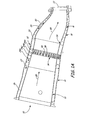
- FIG. 1A is a cross section of a combustor assembly with a baffle ring.
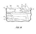
- FIG. 1B is an enlarged cross section of the combustor assembly with the baffle ring.
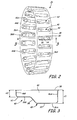
- FIG. 2 is a perspective view of the baffle ring.
- FIG. 3 is a cross section of the baffle ring taken along line 3-3 of FIG. 2 .
- FIG. 4 is a flow diagram illustrating air flow in the combustor assembly of FIG. 1A .
- FIGS. 1A and 1B illustrate combustor assembly 10 that includes combustor liner 12, flow sleeve 14, transition duct 16, impingement sleeve 18 and baffle ring 36.
- Combustor liner 12 is connected to transition duct 16.
- hot gases indicated by arrows 20, flow through combustor liner 12, into transition duct 16 and exit combustor assembly 10 through exit 22 to a turbine (not shown).
- Flow sleeve 14 surrounds combustor liner 12 and is formed with a plurality of rows of cooling holes 24A, 24B, 24C, 24D (generally referred to as cooling holes 24).
- First flow annulus 26 is formed between combustor liner 12 and flow sleeve 14. Cooling air enters as jet-like flow into first flow annulus 26 through cooling holes 24, and impinges upon combustor liner 12 to cool it. After impingement, the spent cooling air flows generally parallel to combustor liner 12 in first flow annulus 26. The flow of spent cooling air through first flow annulus 26 is indicated by arrow 27.
- Impingement sleeve 18 surrounds transition duct 16. Second flow annulus 28 is formed between transition duct 16 and impingement sleeve 18. Impingement sleeve 18 is formed with a plurality of rows of cooling holes 30. Similar to the impingement of combustor liner 12, cooling air enters second flow annulus 28 through cooling holes 30 and impinges upon transition duct 16 to cool it. After impingement, the spent cooling air flows generally parallel to transition duct 16 in second flow annulus 28. The flow of spent cooling air through second flow annulus 28 is indicated by arrow 29.
- Combustor liner 12 and transition duct 16 are connected by sliding seal 34.
- Flow sleeve 14 and impingement sleeve 18 are connected at sliding joint and piston (seal) ring 32 so that first flow annulus 26 and second flow annulus 28 create a continuous flow path.
- piston (seal) ring 32 After impingement on transition duct 16, spent cooling air from second flow annulus 28 continues downstream into first flow annulus 26.
- Baffle ring 36 includes a plurality of lands 38 and baffles 40.
- Baffles 40 extend radially inwards towards combustor liner 12 so that the cooling air flow is closer to combustor liner 12 and the cross flow effects are decreased.
- baffle ring 36 is about 25% longer than baffles 40.
- Lands 38 are located between baffles 40. Lands 38 provide passage for air flow from second flow annulus 28.
- Baffles 40 and lands 38 may be the same width or may be different widths. In one example, baffles 40 are about one third wider than lands 38.
- Baffle ring 36 lies in first flow annulus 26 and surrounds a section of combustor liner 12. Baffle ring 36 is sized to fit against the inner surface of flow sleeve 14 so that lands 38 are in contact with flow sleeve 14.
- Baffle ring 36 may be attached to flow sleeve 14 by mechanical fastening means. In one example, two rows of rivets 39 may attach baffle ring 36 to flow sleeve 14. In another example, baffle ring 36 may be welded to flow sleeve 14.
- Baffle ring 36 is formed so that when baffle ring 36 is in place, baffles 40 align with cooling holes 24 and lands 38 do not align with cooling holes 24.
- cooling air flows through cooling holes 24 into baffles 40, and impinges on combustor liner 12.
- Lands 38 fit against the inner surface of flow sleeve 14. Lands 38 provide flow passage through first flow annulus 26. Lands 38 do not block the air flow from second flow annulus 28 into first flow annulus 26. This prevents a pressure drop between annulus 26 and annulus 28.
- FIG. 2 shows an enlarged perspective view of baffle ring 36.
- Baffle ring 36 has a plurality of baffles 40 that extend radially inwards.
- Each baffle 40 has a pocket 42 defined by sidewalls 44A, 44B, end walls 46A, 46B, and bottom 48.
- Baffle 40 has upstream section 50, downstream section 52, and transition section 54. "Upstream” and “downstream” are determined with respect to the flow of cooling air through flow annuluses 26, 28.
- Sections 50, 52, and 54 may be the same length or may be different lengths. In one example, upstream section 50 is longer than downstream section 52, and downstream section 52 is longer than transition section 54.
- baffle cooling hole 56A is formed in each baffle bottom 48.
- baffle cooling holes 56A, 56B may be formed in each baffle 40.
- Baffle cooling holes 56A, 56B (referred to generally as baffle cooling holes 56) may be aligned with cooling holes 24.
- baffle cooling hole 56A is aligned with cooling hole 24A and baffle cooling hole 56B is aligned with cooling hole 24B, where cooling hole 24A is adjacent to impingement sleeve 18 and cooling hole 24B is adjacent to cooling hole 24A.
- baffle cooling holes 56A, 56B depends on the desired cooling flow rate. Larger baffle cooling holes 56A, 56B provide more cooling air to combustor liner 12.
- the diameter of baffle cooling holes 56A may be the same or different than baffle cooling hole 56B.
- baffle cooling hole 56A has a smaller diameter than baffle cooling hole 56B.
- baffle cooling hole 56B is about 45% larger in diameter than baffle cooling hole 56A.
- baffle cooling hole 56A has a diameter of 0.52 about inches (1.3 cm) and baffle cooling hole 56B has a diameter of about 0.75 inches (1.9 cm).
- the diameters of cooling holes 24 may be the same as or may be larger than the diameters of baffle cooling holes 56. In one example, the diameters of cooling holes 24 are larger than the diameters of the baffle cooling holes 56 with which they are aligned so that the smaller baffle cooling holes 56 set the flow resistance and meter the cooling air flowing into first flow annulus 26.
- FIG. 3 shows a cross section of baffle 40 taken along line 3-3 in FIG. 2 .
- Each baffle 40 has a depth measured from land 38 to baffle bottom 48.
- Baffle 40 may have a uniform depth throughout or the depth may vary within a single baffle 40. In one example, the depth of baffle 40 varies over the length of baffle 40.
- Upstream section 50 has depth d1 and downstream section 52 has depth d2. In one example, depth d1 of upstream section 50 is deeper than depth d2 of downstream section 52. In another example, depth d1 is about twice depth d2.
- baffle bottom 48 of transition section 54 In order to extend between baffle bottom 48 of upstream section 50 and baffle bottom 48 of downstream section 52 when upstream section 50 and downstream section 52 have different depths, baffle bottom 48 of transition section 54 must be at an angle. In one example, baffle bottom 48 of transition section 54 is at about a thirty degree angle to baffle bottom 48 of upstream section 50.
- baffle bottom 48 of upstream section 50 may be closer to or farther away from combustor liner 12 than baffle bottom 48 of downstream section 52.
- baffle bottom 48 of upstream section 50 is closer to combustor liner 12 than baffle bottom 48 of downstream section 52.
- FIG. 4 is a flow diagram illustrating air flow through combustor assembly 10.
- Air flow F flows from second flow annulus 28 into first flow annulus 26, and cooling air jets G, J and M flow through cooling holes 24 to impingement cool combustor liner 12.
- cooling air jet G enters baffle 40 through cooling hole 24A. Cooling air jet G exits baffle 40 through baffle hole 56A and impinges on combustor liner 12. Having baffle hole 56A closer to the liner reduces the cross flow effect on cooling air jet G.
- cooling air jet J enters baffle 40 through cooling hole 24B, exits through baffle hole 56B, and impinges on combustor liner 12. Cooling air jets J and G combine with air flow F to form air flow L. Cooling air L has relatively little effect on downstream cooling air jet M.
- Baffle 40 extends into first flow annulus 26 and guides cooling air jets G and J, ensuring that combustor liner 12 is impinged at the desired point. End wall 46A deflects air flow F downward so that the air flows between baffle bottom 48 and combustor liner 12.
- upstream section 50 of baffle 40 may be deeper or the baffle bottom 48 of upstream section 50 may be closer to combustor liner 12 than downstream section 52.
- upstream section 50 of baffle 40 blocks the cross flow for downstream section 52. Therefore, downstream section 52 does not encounter as much cross flow as upstream section 50 and it is not necessary for downstream section 52 to be as close to combustor liner 12.
- Baffle ring 36 is a one-piece assembly.
- prior art assemblies inserted a plurality of individual tubes or conduits into cooling holes 24.
- in one prior art assembly as many as 48 individual tubes were welding into cooling holes 24. This is expensive and labor intensive. The large number of pieces also increases the probability that a piece will come loose and cause damage to downstream turbine blades and vanes. This is known as foreign object damage (FOD).
- FOD foreign object damage
- baffle ring 36 has been described as being part of a new combustor assembly, baffle ring may be added to an existing combustor assembly to provide a more efficient cooling flow to the liner and improve impingement cooling.
Landscapes
- Engineering & Computer Science (AREA)
- Chemical & Material Sciences (AREA)
- Combustion & Propulsion (AREA)
- Mechanical Engineering (AREA)
- General Engineering & Computer Science (AREA)
- Turbine Rotor Nozzle Sealing (AREA)
Applications Claiming Priority (1)
| Application Number | Priority Date | Filing Date | Title |
|---|---|---|---|
| US12/179,671 US8291711B2 (en) | 2008-07-25 | 2008-07-25 | Flow sleeve impingement cooling baffles |
Publications (2)
| Publication Number | Publication Date |
|---|---|
| EP2148140A2 true EP2148140A2 (de) | 2010-01-27 |
| EP2148140A3 EP2148140A3 (de) | 2013-03-20 |
Family
ID=40578717
Family Applications (1)
| Application Number | Title | Priority Date | Filing Date |
|---|---|---|---|
| EP09251001A Withdrawn EP2148140A3 (de) | 2008-07-25 | 2009-03-31 | Muffenartiges Leitblech mit Prallkühlung |
Country Status (2)
| Country | Link |
|---|---|
| US (2) | US8291711B2 (de) |
| EP (1) | EP2148140A3 (de) |
Cited By (4)
| Publication number | Priority date | Publication date | Assignee | Title |
|---|---|---|---|---|
| CN103032893A (zh) * | 2011-10-05 | 2013-04-10 | 通用电气公司 | 燃烧器和用于将流供应到燃烧器的方法 |
| WO2013184495A2 (en) | 2012-06-07 | 2013-12-12 | United Technologies Corporation | Combustor liner with decreased liner cooling |
| EP2728255A1 (de) * | 2012-10-31 | 2014-05-07 | Alstom Technology Ltd | Heißgas-Segmentanordnung |
| WO2016151550A1 (en) * | 2015-03-26 | 2016-09-29 | Ansaldo Energia Switzerland AG | Flow sleeve deflector for use in gas turbine combustor |
Families Citing this family (17)
| Publication number | Priority date | Publication date | Assignee | Title |
|---|---|---|---|---|
| US8646276B2 (en) * | 2009-11-11 | 2014-02-11 | General Electric Company | Combustor assembly for a turbine engine with enhanced cooling |
| US9869279B2 (en) * | 2012-11-02 | 2018-01-16 | General Electric Company | System and method for a multi-wall turbine combustor |
| US20140137560A1 (en) * | 2012-11-21 | 2014-05-22 | General Electric Company | Turbomachine with trapped vortex feature |
| US9617870B2 (en) | 2013-02-05 | 2017-04-11 | United Technologies Corporation | Bracket for mounting a stator guide vane arrangement to a strut in a turbine engine |
| WO2014179328A1 (en) * | 2013-04-29 | 2014-11-06 | United Technologies Corporation | Joint for sealing a gap between casing segments of an industrial gas turbine engine combustor |
| US9494081B2 (en) | 2013-05-09 | 2016-11-15 | Siemens Aktiengesellschaft | Turbine engine shutdown temperature control system with an elongated ejector |
| US9777600B2 (en) * | 2015-06-04 | 2017-10-03 | General Electric Company | Installation apparatus and related methods for coupling flow sleeve and transition piece |
| US10184343B2 (en) * | 2016-02-05 | 2019-01-22 | General Electric Company | System and method for turbine nozzle cooling |
| EP3242084A1 (de) * | 2016-05-04 | 2017-11-08 | Siemens Aktiengesellschaft | Brennkammeranordnung mit prallplatten zur umleitung eines kühlluftstroms in gasturbinenmotoren |
| US10495311B2 (en) * | 2016-06-28 | 2019-12-03 | DOOSAN Heavy Industries Construction Co., LTD | Transition part assembly and combustor including the same |
| US10641490B2 (en) | 2017-01-04 | 2020-05-05 | General Electric Company | Combustor for use in a turbine engine |
| US10823418B2 (en) | 2017-03-02 | 2020-11-03 | General Electric Company | Gas turbine engine combustor comprising air inlet tubes arranged around the combustor |
| KR101986729B1 (ko) * | 2017-08-22 | 2019-06-07 | 두산중공업 주식회사 | 실 영역 집중냉각을 위한 냉각유로 구조 및 이를 포함하는 가스 터빈용 연소기 |
| DE102017125051A1 (de) * | 2017-10-26 | 2019-05-02 | Man Diesel & Turbo Se | Strömungsmaschine |
| US11340184B2 (en) * | 2018-11-05 | 2022-05-24 | General Electric Company | Engine component performance inspection sleeve and method of inspecting engine component |
| US11204169B2 (en) | 2019-07-19 | 2021-12-21 | Pratt & Whitney Canada Corp. | Combustor of gas turbine engine and method |
| CN117146296A (zh) | 2022-05-24 | 2023-12-01 | 通用电气公司 | 具有稀释冷却衬里的燃烧器 |
Citations (3)
| Publication number | Priority date | Publication date | Assignee | Title |
|---|---|---|---|---|
| US20050150632A1 (en) | 2004-01-09 | 2005-07-14 | Mayer Robert R. | Extended impingement cooling device and method |
| US20060168967A1 (en) | 2005-01-31 | 2006-08-03 | General Electric Company | Inboard radial dump venturi for combustion chamber of a gas turbine |
| US20060283189A1 (en) | 2005-06-15 | 2006-12-21 | General Electric Company | Axial flow sleeve for a turbine combustor and methods of introducing flow sleeve air |
Family Cites Families (21)
| Publication number | Priority date | Publication date | Assignee | Title |
|---|---|---|---|---|
| US1380A (en) * | 1839-10-26 | Machine foe | ||
| US2816763A (en) * | 1955-12-27 | 1957-12-17 | George D Lyles | Combination merry-go-round and ferris wheel |
| CH633347A5 (de) | 1978-08-03 | 1982-11-30 | Bbc Brown Boveri & Cie | Gasturbine. |
| USH1380H (en) * | 1991-04-17 | 1994-12-06 | Halila; Ely E. | Combustor liner cooling system |
| DE4239856A1 (de) | 1992-11-27 | 1994-06-01 | Asea Brown Boveri | Gasturbinenbrennkammer |
| JP3415663B2 (ja) | 1992-12-28 | 2003-06-09 | アルストム | 冷却面を衝撃式に冷却するための装置 |
| US5363654A (en) | 1993-05-10 | 1994-11-15 | General Electric Company | Recuperative impingement cooling of jet engine components |
| JP3110227B2 (ja) | 1993-11-22 | 2000-11-20 | 株式会社東芝 | タービン冷却翼 |
| DE4430302A1 (de) | 1994-08-26 | 1996-02-29 | Abb Management Ag | Prallgekühltes Wandteil |
| GB9505067D0 (en) * | 1995-03-14 | 1995-05-03 | Europ Gas Turbines Ltd | Combustor and operating method for gas or liquid-fuelled turbine |
| US5782294A (en) | 1995-12-18 | 1998-07-21 | United Technologies Corporation | Cooled liner apparatus |
| US5665002A (en) * | 1996-02-29 | 1997-09-09 | Balwanz; C. Grant | Chair assembly for an amusement ride |
| US6000908A (en) | 1996-11-05 | 1999-12-14 | General Electric Company | Cooling for double-wall structures |
| US6484505B1 (en) | 2000-02-25 | 2002-11-26 | General Electric Company | Combustor liner cooling thimbles and related method |
| US6606861B2 (en) | 2001-02-26 | 2003-08-19 | United Technologies Corporation | Low emissions combustor for a gas turbine engine |
| EP1271056A1 (de) | 2001-06-20 | 2003-01-02 | Siemens Aktiengesellschaft | Gasturbinen-Brennkammer und für diese vorgesehenes Verfahren zur Luftführung |
| US6701714B2 (en) | 2001-12-05 | 2004-03-09 | United Technologies Corporation | Gas turbine combustor |
| DE50212796D1 (de) | 2002-12-19 | 2008-10-30 | Siemens Ag | Geschlossen gekühlte Brennkammer für eine Turbine |
| US6711900B1 (en) * | 2003-02-04 | 2004-03-30 | Pratt & Whitney Canada Corp. | Combustor liner V-band design |
| US7010921B2 (en) * | 2004-06-01 | 2006-03-14 | General Electric Company | Method and apparatus for cooling combustor liner and transition piece of a gas turbine |
| US7278256B2 (en) * | 2004-11-08 | 2007-10-09 | United Technologies Corporation | Pulsed combustion engine |
-
2008
- 2008-07-25 US US12/179,671 patent/US8291711B2/en not_active Expired - Fee Related
-
2009
- 2009-03-31 EP EP09251001A patent/EP2148140A3/de not_active Withdrawn
-
2012
- 2012-07-19 US US13/553,076 patent/US8794006B2/en not_active Expired - Fee Related
Patent Citations (3)
| Publication number | Priority date | Publication date | Assignee | Title |
|---|---|---|---|---|
| US20050150632A1 (en) | 2004-01-09 | 2005-07-14 | Mayer Robert R. | Extended impingement cooling device and method |
| US20060168967A1 (en) | 2005-01-31 | 2006-08-03 | General Electric Company | Inboard radial dump venturi for combustion chamber of a gas turbine |
| US20060283189A1 (en) | 2005-06-15 | 2006-12-21 | General Electric Company | Axial flow sleeve for a turbine combustor and methods of introducing flow sleeve air |
Cited By (5)
| Publication number | Priority date | Publication date | Assignee | Title |
|---|---|---|---|---|
| CN103032893A (zh) * | 2011-10-05 | 2013-04-10 | 通用电气公司 | 燃烧器和用于将流供应到燃烧器的方法 |
| WO2013184495A2 (en) | 2012-06-07 | 2013-12-12 | United Technologies Corporation | Combustor liner with decreased liner cooling |
| EP2859204A4 (de) * | 2012-06-07 | 2016-03-16 | United Technologies Corp | Brennkammerwand mit verminderter wandkühlung |
| EP2728255A1 (de) * | 2012-10-31 | 2014-05-07 | Alstom Technology Ltd | Heißgas-Segmentanordnung |
| WO2016151550A1 (en) * | 2015-03-26 | 2016-09-29 | Ansaldo Energia Switzerland AG | Flow sleeve deflector for use in gas turbine combustor |
Also Published As
| Publication number | Publication date |
|---|---|
| US8794006B2 (en) | 2014-08-05 |
| US20130000310A1 (en) | 2013-01-03 |
| EP2148140A3 (de) | 2013-03-20 |
| US20100031666A1 (en) | 2010-02-11 |
| US8291711B2 (en) | 2012-10-23 |
Similar Documents
| Publication | Publication Date | Title |
|---|---|---|
| US8291711B2 (en) | Flow sleeve impingement cooling baffles | |
| EP2148139B1 (de) | Fließhülsen-Prallkühlung mit einem Plenumring | |
| EP3211319B1 (de) | Brennkammer | |
| EP3176372B1 (de) | Gekühltes bauteil einer turbomaschine | |
| US9810081B2 (en) | Cooled conduit for conveying combustion gases | |
| US9625152B2 (en) | Combustor heat shield for a gas turbine engine | |
| EP3006831B1 (de) | Gekühltes bauteil | |
| EP2211105A2 (de) | Hinterkantenverkleidungsanordnung einer Brennkammerwand mit Turbulatoren und dazugehöriges Kühlungsverfahren | |
| EP2363644A2 (de) | Hybrides Venturikühlsystem | |
| US20100034643A1 (en) | Transition duct aft end frame cooling and related method | |
| US11280198B2 (en) | Turbine engine with annular cavity | |
| US20160209035A1 (en) | Combustion hole insert with integrated film restarter | |
| US20090255268A1 (en) | Divergent cooling thimbles for combustor liners and related method | |
| US9188336B2 (en) | Assemblies and apparatus related to combustor cooling in turbine engines | |
| EP2562479A2 (de) | Wandelemente für Gasturbinenmotoren | |
| CN104564351A (zh) | 冲击冷却组件 | |
| CA2802062C (en) | Combustor for gas turbine engine | |
| CN107143382B (zh) | 用于先进膜冷却的具有小复杂特征的cmc制品 | |
| JP2014009937A (ja) | ガスタービン用移行ダクト | |
| EP2230456A2 (de) | Brennermantel mit Mischlochansatz | |
| US10113745B2 (en) | Flow sleeve deflector for use in gas turbine combustor | |
| EP2730748A2 (de) | Kühlsystem zum Kühlen einer Heißgaskomponente, zugehörige Gasturbinenbrennkammer und Kühlverfahren | |
| EP3179167A1 (de) | Einscahlige brennkammerwand mit wärmetransfererhöhenden elementen | |
| CN116105175B (zh) | 燃烧衬里 |
Legal Events
| Date | Code | Title | Description |
|---|---|---|---|
| PUAI | Public reference made under article 153(3) epc to a published international application that has entered the european phase |
Free format text: ORIGINAL CODE: 0009012 |
|
| AK | Designated contracting states |
Kind code of ref document: A2 Designated state(s): AT BE BG CH CY CZ DE DK EE ES FI FR GB GR HR HU IE IS IT LI LT LU LV MC MK MT NL NO PL PT RO SE SI SK TR |
|
| AX | Request for extension of the european patent |
Extension state: AL BA RS |
|
| PUAL | Search report despatched |
Free format text: ORIGINAL CODE: 0009013 |
|
| AK | Designated contracting states |
Kind code of ref document: A3 Designated state(s): AT BE BG CH CY CZ DE DK EE ES FI FR GB GR HR HU IE IS IT LI LT LU LV MC MK MT NL NO PL PT RO SE SI SK TR |
|
| AX | Request for extension of the european patent |
Extension state: AL BA RS |
|
| RIC1 | Information provided on ipc code assigned before grant |
Ipc: F23R 3/06 20060101AFI20130212BHEP Ipc: F23R 3/08 20060101ALI20130212BHEP |
|
| 17P | Request for examination filed |
Effective date: 20130920 |
|
| RBV | Designated contracting states (corrected) |
Designated state(s): AT BE BG CH CY CZ DE DK EE ES FI FR GB GR HR HU IE IS IT LI LT LU LV MC MK MT NL NO PL PT RO SE SI SK TR |
|
| AKX | Designation fees paid |
Designated state(s): DE GB |
|
| RAP1 | Party data changed (applicant data changed or rights of an application transferred) |
Owner name: PW POWER SYSTEMS, INC. |
|
| 17Q | First examination report despatched |
Effective date: 20160413 |
|
| STAA | Information on the status of an ep patent application or granted ep patent |
Free format text: STATUS: THE APPLICATION IS DEEMED TO BE WITHDRAWN |
|
| 18D | Application deemed to be withdrawn |
Effective date: 20161025 |