EP2148163A2 - Dispositif à échange de chaleur à circuit unique pour pompage directionnel inverse et positif périodique - Google Patents
Dispositif à échange de chaleur à circuit unique pour pompage directionnel inverse et positif périodique Download PDFInfo
- Publication number
- EP2148163A2 EP2148163A2 EP09251865A EP09251865A EP2148163A2 EP 2148163 A2 EP2148163 A2 EP 2148163A2 EP 09251865 A EP09251865 A EP 09251865A EP 09251865 A EP09251865 A EP 09251865A EP 2148163 A2 EP2148163 A2 EP 2148163A2
- Authority
- EP
- European Patent Office
- Prior art keywords
- fluid
- pumping
- heat exchanger
- periodic
- pump
- Prior art date
- Legal status (The legal status is an assumption and is not a legal conclusion. Google has not performed a legal analysis and makes no representation as to the accuracy of the status listed.)
- Withdrawn
Links
- 238000005086 pumping Methods 0.000 title claims abstract description 313
- 230000002441 reversible effect Effects 0.000 title claims abstract description 114
- 230000000737 periodic effect Effects 0.000 title claims description 121
- 239000012530 fluid Substances 0.000 claims abstract description 728
- 239000000463 material Substances 0.000 claims abstract description 23
- 239000002274 desiccant Substances 0.000 claims abstract description 12
- 230000000694 effects Effects 0.000 claims abstract description 3
- 230000002457 bidirectional effect Effects 0.000 claims description 100
- 239000007788 liquid Substances 0.000 claims description 37
- 230000008859 change Effects 0.000 claims description 18
- 230000002427 irreversible effect Effects 0.000 claims description 8
- 230000008878 coupling Effects 0.000 claims description 4
- 238000010168 coupling process Methods 0.000 claims description 4
- 238000005859 coupling reaction Methods 0.000 claims description 4
- 238000000034 method Methods 0.000 claims description 3
- 239000007787 solid Substances 0.000 claims description 2
- 238000007791 dehumidification Methods 0.000 abstract description 10
- 239000012535 impurity Substances 0.000 abstract description 4
- 230000035508 accumulation Effects 0.000 abstract description 3
- 238000009825 accumulation Methods 0.000 abstract description 3
- 238000011084 recovery Methods 0.000 abstract description 3
- 238000010586 diagram Methods 0.000 description 6
- 230000001737 promoting effect Effects 0.000 description 3
- 239000003344 environmental pollutant Substances 0.000 description 2
- 231100000719 pollutant Toxicity 0.000 description 2
- 238000010521 absorption reaction Methods 0.000 description 1
- 230000007547 defect Effects 0.000 description 1
- 230000008569 process Effects 0.000 description 1
Images




Classifications
-
- F—MECHANICAL ENGINEERING; LIGHTING; HEATING; WEAPONS; BLASTING
- F28—HEAT EXCHANGE IN GENERAL
- F28F—DETAILS OF HEAT-EXCHANGE AND HEAT-TRANSFER APPARATUS, OF GENERAL APPLICATION
- F28F13/00—Arrangements for modifying heat-transfer, e.g. increasing, decreasing
- F28F13/06—Arrangements for modifying heat-transfer, e.g. increasing, decreasing by affecting the pattern of flow of the heat-exchange media
-
- F—MECHANICAL ENGINEERING; LIGHTING; HEATING; WEAPONS; BLASTING
- F24—HEATING; RANGES; VENTILATING
- F24F—AIR-CONDITIONING; AIR-HUMIDIFICATION; VENTILATION; USE OF AIR CURRENTS FOR SCREENING
- F24F3/00—Air-conditioning systems in which conditioned primary air is supplied from one or more central stations to distributing units in the rooms or spaces where it may receive secondary treatment; Apparatus specially designed for such systems
- F24F3/12—Air-conditioning systems in which conditioned primary air is supplied from one or more central stations to distributing units in the rooms or spaces where it may receive secondary treatment; Apparatus specially designed for such systems characterised by the treatment of the air otherwise than by heating and cooling
- F24F3/14—Air-conditioning systems in which conditioned primary air is supplied from one or more central stations to distributing units in the rooms or spaces where it may receive secondary treatment; Apparatus specially designed for such systems characterised by the treatment of the air otherwise than by heating and cooling by humidification; by dehumidification
- F24F3/1411—Air-conditioning systems in which conditioned primary air is supplied from one or more central stations to distributing units in the rooms or spaces where it may receive secondary treatment; Apparatus specially designed for such systems characterised by the treatment of the air otherwise than by heating and cooling by humidification; by dehumidification by absorbing or adsorbing water, e.g. using an hygroscopic desiccant
-
- F—MECHANICAL ENGINEERING; LIGHTING; HEATING; WEAPONS; BLASTING
- F28—HEAT EXCHANGE IN GENERAL
- F28D—HEAT-EXCHANGE APPARATUS, NOT PROVIDED FOR IN ANOTHER SUBCLASS, IN WHICH THE HEAT-EXCHANGE MEDIA DO NOT COME INTO DIRECT CONTACT
- F28D21/00—Heat-exchange apparatus not covered by any of the groups F28D1/00 - F28D20/00
-
- F—MECHANICAL ENGINEERING; LIGHTING; HEATING; WEAPONS; BLASTING
- F28—HEAT EXCHANGE IN GENERAL
- F28F—DETAILS OF HEAT-EXCHANGE AND HEAT-TRANSFER APPARATUS, OF GENERAL APPLICATION
- F28F19/00—Preventing the formation of deposits or corrosion, e.g. by using filters or scrapers
-
- F—MECHANICAL ENGINEERING; LIGHTING; HEATING; WEAPONS; BLASTING
- F28—HEAT EXCHANGE IN GENERAL
- F28F—DETAILS OF HEAT-EXCHANGE AND HEAT-TRANSFER APPARATUS, OF GENERAL APPLICATION
- F28F27/00—Control arrangements or safety devices specially adapted for heat-exchange or heat-transfer apparatus
- F28F27/02—Control arrangements or safety devices specially adapted for heat-exchange or heat-transfer apparatus for controlling the distribution of heat-exchange media between different channels
-
- F—MECHANICAL ENGINEERING; LIGHTING; HEATING; WEAPONS; BLASTING
- F24—HEATING; RANGES; VENTILATING
- F24F—AIR-CONDITIONING; AIR-HUMIDIFICATION; VENTILATION; USE OF AIR CURRENTS FOR SCREENING
- F24F12/00—Use of energy recovery systems in air conditioning, ventilation or screening
- F24F12/001—Use of energy recovery systems in air conditioning, ventilation or screening with heat-exchange between supplied and exhausted air
- F24F2012/008—Use of energy recovery systems in air conditioning, ventilation or screening with heat-exchange between supplied and exhausted air cyclic routing supply and exhaust air
-
- F—MECHANICAL ENGINEERING; LIGHTING; HEATING; WEAPONS; BLASTING
- F28—HEAT EXCHANGE IN GENERAL
- F28F—DETAILS OF HEAT-EXCHANGE AND HEAT-TRANSFER APPARATUS, OF GENERAL APPLICATION
- F28F2250/00—Arrangements for modifying the flow of the heat exchange media, e.g. flow guiding means; Particular flow patterns
- F28F2250/08—Fluid driving means, e.g. pumps, fans
-
- Y—GENERAL TAGGING OF NEW TECHNOLOGICAL DEVELOPMENTS; GENERAL TAGGING OF CROSS-SECTIONAL TECHNOLOGIES SPANNING OVER SEVERAL SECTIONS OF THE IPC; TECHNICAL SUBJECTS COVERED BY FORMER USPC CROSS-REFERENCE ART COLLECTIONS [XRACs] AND DIGESTS
- Y02—TECHNOLOGIES OR APPLICATIONS FOR MITIGATION OR ADAPTATION AGAINST CLIMATE CHANGE
- Y02B—CLIMATE CHANGE MITIGATION TECHNOLOGIES RELATED TO BUILDINGS, e.g. HOUSING, HOUSE APPLIANCES OR RELATED END-USER APPLICATIONS
- Y02B30/00—Energy efficient heating, ventilation or air conditioning [HVAC]
- Y02B30/56—Heat recovery units
Definitions
- the present invention further improves the conventional applications for various heat exchange device or full heat exchange device to have the single flow circuit heat exchange operating functional structure for controllable periodic positive and reverse directional pumping, wherein the periodic positive and reverse directional pumping fluid is passed through the heat exchanger inside the fluid pump to constitute heat exchange function of the heat exchange device thereby timely improving the temperature distribution status between the fluid and the heat exchanger and promoting the heat exchange efficiency of the heat exchange device; further, by periodic positive and reverse directional pumping fluid in the single flow circuit to pass through the full heat exchanger constituted by heat exchangers being interposed or coated with permeating type or absorption type desiccant material, or passed through the full heat exchanger itself being made of material or structure having both heat absorbing and moisture absorbing function thereby constituting the full heat exchange function of the full heat exchanger for thermal energy recovery and dehumidification functional operations of heat exchange and for reducing the defects of impurity accumulation due to fixed directional flow.
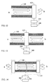
- Fig. 1 is a main structure block schematic view of the conventional single flow circuit flow pumping device in fixed flow direction; it includes being applied in the heat exchange device or full heat exchange device; as shown in Fig. 1 , the fluid is pumped in the fluid port at side with different temperature and discharged out of the fluid port at another side with different temperature by the unidirectional fluid pump (120), and as the fluid flow direction is fixed, the temperature difference distribution gradient inside the heat exchanger is unchanged;
- Fig. 2 is the temperature distribution diagram of the conventional single flow directional pumping thermal fluid; in which the temperature difference between the heat exchanger and the single flow pumping fluid is gradually approached along with the accumulated time thereby gradually reducing its functions;
- FIG. 3 is a schematic view showing structure principles of the heat exchanger in Fig. 1 being replaced to the full heat exchanger having heat exchange function and dehumidification function.
- the present invention discloses that the conventional heat exchange device having fixed directional pumping fluids is improved to have the single flow-circuit operational function of periodic positive and reverse directional pumping thereby obtaining following one or more than one functions, including: 1) the temperature difference distribution status at the two ends between the fluid and the heat exchanger (100) inside the heat exchange device during heat absorbing and release operating process is changed by periodic positive and reverse directional pumping fluid to appear different flow directions thereby promoting the heat exchange efficiency of the heat exchange device; 2) for full heat exchange applications of the heat exchanger (100) being interposed or coated with permeating type or absorbing type desiccant material, or the material or structure of the heat exchanger itself being the full heat exchanger (200) having both moisture absorbing function, or the fluid piping being externally series connected with full heat exchange device, or series connected with piping having full heat exchange functions of heat exchange and moisture absorbing functions, the flow rate, or flow direction, or both of fluid is periodically manipulated to change, thereby allowing the temperature and humidity saturation degrees differences between the fluid and the heat exchanger
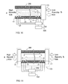
- Fig. 4 is the first schematic view showing structure principles of the single flow circuit heat exchange device for periodic positive and reverse directional pumping of the present invention being installed with a bidirectional fluid pump with positive and reverse pumping fluid function on one side thereof.
- the single flow circuit heat exchange device for periodic positive and reverse directional pumping of the present invention is further installed a bidirectional fluid pump with positive and reverse directional pumping function to one end of the conventional heat exchange device for constituting the bidirectional fluid pumping device (123), and installed with the periodic fluid direction-change operative control device (250) for operatively controlling the bidirectional fluid pumping device (123) so as to make the fluid originally pumped in fixed flow direction appear periodically alternately flow directional change;
- the timings for fluid for periodic flow direction change are that 1) the pumping direction of the bidirectional fluid pumping device (123) is manually operatively controlled, 2) the pumping direction of the bidirectional fluid pumping device (123) is operatively controlled by the periodic fluid direction-change operative control device (250) through setting time period according to temperature variations, or 3) the at least one temperature detecting device (11) is installed at position capable of directly or indirectly detecting the temperature variation of fluid, wherein the detecting signals of the temperature detecting device (11) are transmitted to the periodic fluid direction-change operative control device (250), so as when the setting temperature is reached, the pumping direction of the bidirectional fluid pumping device (123) is operatively controlled to pump the fluid in reverse flow direction.
- Fig. 5 is the temperature distribution variation diagram between the thermal fluid and the piping during the operation as shown in Fig. 4 .
- Fig. 5 is to operatively control the fluid passing through the heat exchanger (100) installed in the heat exchange device for periodically changing fluid pumping direction; take the heat exchange device for indoor-outdoor air change in cold winter times as example, wherein the higher indoor temperature air flow is pumped through the heat exchange device via fluid port (a) and is discharged to outdoors via fluid port (b) of heat exchanger by the bidirectional fluid pumping device (123) driven by the power of power source (300), the heat exchanger (100) of the heat exchange device is then gradually formed with a temperature distribution from high temperature at fluid port (a) to the lower temperature at fluid port (b), and it is through that 1) the pumping direction of the bidirectional fluid pumping device (123) is manually operatively controlled, or 2) the pumping direction of the bidirectional fluid pumping device (123) is operatively controlled by the periodic fluid direction-change operative control device (250) through setting time period according to temperature variations, or 3) the at least one temperature detecting device (11) is installed at position capable of directly or indirectly detecting the temperature variation of fluid
- Fig. 6 is a schematic view showing structure principles of the heat exchanger in Fig. 4 being replaced to the full heat exchanger having both heat exchange function and dehumidification function.
- Fig. 6 shows that the device for periodic positive and reverse directional pumping fluid as shown in Fig. 4 being applied for the full heat exchange device (200) having the heat exchanger being interposed or coated with permeating type or absorbing type desiccant material, or the heat exchanger of the full heat exchanger itself being made of material or structure further having moisture absorbing function is through that 1) the pumping direction of the bidirectional fluid pumping device (123) is manually operatively controlled, or 2) the pumping direction of the bidirectional fluid pumping device (123) is operatively controlled by the periodic fluid direction-change operative control device (250) through setting time period according to temperature variations, or setting time period according to humidity variations, or setting time period according to temperature and humidity variations simultaneously, or 3) the at least one temperature detecting device (11) and at least one humidity detecting device (21) are installed at position capable of directly or indirectly detecting the temperature variation and humidity variation of fluid, which includes being installed with both or at least one detecting device, wherein the detecting signals of the temperature detecting device (11) and the humidity detecting device (21)
- Said temperature detecting device (11) and the humidity detecting device (21) can be in an integral structure or separated installed.
- the single flow circuit heat exchange device for periodic positive and reverse directional pumping of the present invention can be selected to constitute the function of the bidirectional fluid pumping device (123) by two series-connected unidirectional fluid pumps at different pumping directions;
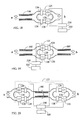
- Fig. 7 is the second schematic view showing structure principles of the single flow circuit heat exchange device having the bidirectional fluid pumping device being constituted by two unidirectional fluid pumps in different flow pumping directions;
- Fig. 7 is to replace the fluid pump with positive and reverse directional pumping function of Fig. 4 by two reverse installed unidirectional fluid pumps (120) to pump by turns, which are installed at the two ends of the heat exchanger (100) to constituted the function of the bidirectional fluid pumping device (123), and thereby being subject to the operative control of the periodic fluid direction-change operative control device (250), wherein the operational principal and the control timing are the same with that of the embodiment shown in Fig. 4 .
- Fig. 8 is the temperature distribution variation diagram between the thermal fluid and the piping during the operation as shown in Fig. 7
- Fig. 8 is to operatively control the fluid passing through the heat exchanger (100) installed in the heat exchange device for periodically changing fluid pumping direction; take the heat exchange device for indoor-outdoor air change in cold winter times as example, wherein during the operation of the heat exchanger, the higher indoor temperature air flow is pumped through the heat exchanger (100) via fluid port (a) and is discharged to outdoors via fluid port (b) by the bidirectional fluid pumping device (123) driven by the power of power source (300), the heat exchanger (100) of the heat exchange device is then gradually formed with a temperature distribution from high temperature at fluid port (a) to the lower temperature at fluid port (b), it is then further through that 1) the pumping direction of the bidirectional fluid pumping device (123) is manually operatively controlled, or 2) the pumping direction of the bidirectional fluid pumping device (123) is operatively controlled by the periodic fluid direction-change operative control device (250) through setting time period according to temperature variations, or 3) the at least one temperature detecting device (11) is installed at position capable of directly
- Fig. 9 is a schematic view showing structure principles of the heat exchanger in Fig. 7 being replaced to the full heat exchanger having both heat exchange function and dehumidification function.
- Fig. 9 shows that the device for periodic positive and reverse directional pumping fluid as shown in Fig. 7 being applied for the full heat exchange device (200) having the heat exchanger being interposed or coated with permeating type or absorbing type desiccant material, or for the heat exchanger of the full heat exchanger itself being made of material or structure further having moisture absorbing function is through that 1) the pumping direction of the bidirectional fluid pumping device (123) is manually operatively controlled, or 2) the pumping direction of the bidirectional fluid pumping device (123) is operatively controlled by the periodic fluid direction-change operative control device (250) through setting time period according to temperature variations, or setting time period according to humidity variations, or setting time period according to temperature and humidity variations simultaneously, or 3) the at least one temperature detecting device (11) and at least one humidity detecting device (21) are installed at position capable of directly or indirectly detecting the temperature variation and humidity variation of fluid, which includes being installed with both or at least one detecting device, wherein the detecting signals of the temperature detecting device (11) and the humidity detecting device (2
- Said temperature detecting device (11) and the humidity detecting device (21) can be in an integral structure or separated installed.
- the single flow-circuit heat exchange device for periodic positive and reverse directional pumping of the present invention further can be installed with all or at least one or more than one detecting device of temperature detecting device (11), humidity detecting device (21), and gaseous or liquid fluid composition detecting device (31) on the heat exchange device (1000), heat exchanger (100) or total heat exchanger (200) at positions near both or one of the fluid port (a) and fluid port (b), or at other positions capable of detecting exchanging fluids, wherein the number of aforementioned detecting devices can be one or more than one to provide the detected signal as the reference for the operation of one or more than one functions as follows, including: 1) as the reference for operatively controlling the periodic switch timing of fluid flowing direction pumped by the bi-directional fluid pumping devices (123); or 2) as the reference for operatively controlling the bi-directional fluid pumping devices (123) to control the speed or the flow rate of the pumping fluid; or 3) as the reference for operatively controlling the open volume of the fluid valve to control the speed or the flow rate of
- all detecting devices can be in an integral structure, or partial detecting devices are in an integral structure, or each detecting device is separated installed.
- FIG. 10 is the structural principal schematic view of Fig. 6 being additional installed with the gaseous or liquid fluid composition detecting device.
- Fig. 10 shows that the bi-directional fluid pumping device (123) is constituted by the bidirectional fluid pump with positive and reverse directional pumping function being installed on single side as shown in Fig. 6 for coupling to one end of the full heat exchange device (200) having the heat exchanger being interposed or coated with permeating type or absorbing type desiccant material, or the heat exchanger of the full heat exchanger itself being made of material or structure further having moisture absorbing function is through that 1) the pumping direction of the bidirectional fluid pumping device (123) is manually operatively controlled, or 2) the pumping direction of the bidirectional fluid pumping device (123) is operatively controlled by the periodic fluid direction-change operative control device (250) through setting time period according to temperature variations, or setting time period according to humidity variations, or setting time period according to temperature and humidity variations simultaneously, or 3) the at least one temperature detecting device (11), at least one humidity detecting device (21), and at least one gaseous or liquid fluid composition detecting device (31) are installed at position capable of directly or indirectly detecting the temperature variation
- FIG. 11 is the structural principal schematic view of Fig. 9 being additional installed with the gaseous or liquid fluid composition detecting device.
- Fig. 11 shows that the bi-directional fluid pumping device (123) is constituted by the unidirectional fluid pumps (120) on both sides that pump in reverse direction by turns as shown in Fig. 9 for coupling to both ends of the full heat exchange device (200) having the heat exchanger being interposed or coated with permeating type or absorbing type desiccant material, or for the heat exchanger of the full heat exchanger itself being made of material or structure further having moisture absorbing function is through that 1) the pumping direction of the bidirectional fluid pumping device (123) is manually operatively controlled, or 2) the pumping direction of the bidirectional fluid pumping device (123) is operatively controlled by the periodic fluid direction-change operative control device (250) through setting time period according to temperature variations, or setting time period according to humidity variations, or setting time period according to temperature and humidity variations simultaneously, or 3) the at least one temperature detecting device (11), at least one humidity detecting device (21), and at least one gaseous or liquid fluid composition detecting device (31) are installed at position capable of directly or indirectly detecting the temperature
- Said temperature detecting device (11), humidity detecting device (21), and gaseous or liquid fluid composition detecting device (31) can be in an integral structure or separated installed.
- the selectable but not for limiting embodiments of the bidirectional fluid pumping device (123) of the single flow circuit heat exchange device for periodic positive and reverse directional pumping of the present invention comprises one ore more than one structures as follows, including:
- Said periodic fluid direction-change operative control device (250) of the single flow circuit heat exchange device for periodic positive and reverse directional pumping of the present invention is equipped with electric motor, or controllable engine power, or mechanical or electric power generated or converted from other wind energy, thermal energy, temperature-difference energy, or solar energy for controlling various fluid pumps for driven, or controlling the operation timing of the fluid pumps or fluid valves, thereby changing the direction of the two circuits passing through the heat exchanger (100) and further to operatively control partial or all functions of modulation including the rotational speed, flow rate, fluid pressure of various fluid pumps thereof.
- the operational modes include one or more than one types as follows, including:
- the single flow-circuit heat exchange device for periodic positive and reverse directional pumping of the present invention when installed with the function of operatively controlling the flow rate, the flow rate range of the controlled fluid is between stop delivery to the maximum delivering volume, and the flow rate of fluid is manipulated in stepped or stepless according to the operational requirements, wherein it is further by following one or more than one devices to change the flow rate of fluid, including:
- the flow rate ratio of the two flow circuits passing through the heat exchanger (100) or the total heat exchanger (200) during the operation can be one or more than one ratio modes as follows, including:
- the pumping periodic mode includes one or more than one type as follows, including:
- the heat exchanger or full heat exchanger of the single flow circuit heat exchange device for periodic positive and reverse directional pumping of the present invention is embodied to have the following characteristics: 1) it is of the tubular structure in linear or other geometric shapes; 2) it is constituted by the multi-layer structure having fluid path for passing gaseous or liquid state fluids; or 3) it is constituted by a plurality of single flow path heat exchange device with one or more than one fluid path in series connection, parallel connection or series and parallel connection.
- one or more than one operational methods as follows can be further added to the operational modes of the flow direction change control:
Landscapes
- Engineering & Computer Science (AREA)
- Mechanical Engineering (AREA)
- General Engineering & Computer Science (AREA)
- Physics & Mathematics (AREA)
- Thermal Sciences (AREA)
- Chemical & Material Sciences (AREA)
- Combustion & Propulsion (AREA)
- Central Air Conditioning (AREA)
- Structures Of Non-Positive Displacement Pumps (AREA)
- Drying Of Gases (AREA)
Applications Claiming Priority (2)
| Application Number | Priority Date | Filing Date | Title |
|---|---|---|---|
| US12/219,473 US20100018681A1 (en) | 2008-07-23 | 2008-07-23 | Single flow circuit heat exchange device for periodic positive and reverse directional pumping |
| US12/292,307 US8651171B2 (en) | 2008-11-17 | 2008-11-17 | Single flow circuit heat exchange device for periodic positive and reverse directional pumping |
Publications (2)
| Publication Number | Publication Date |
|---|---|
| EP2148163A2 true EP2148163A2 (fr) | 2010-01-27 |
| EP2148163A3 EP2148163A3 (fr) | 2016-07-27 |
Family
ID=41210492
Family Applications (1)
| Application Number | Title | Priority Date | Filing Date |
|---|---|---|---|
| EP09251865.3A Withdrawn EP2148163A3 (fr) | 2008-07-23 | 2009-07-23 | Dispositif à échange de chaleur à circuit unique pour pompage directionnel inverse et positif périodique |
Country Status (5)
| Country | Link |
|---|---|
| EP (1) | EP2148163A3 (fr) |
| JP (1) | JP2010054188A (fr) |
| CN (1) | CN201628503U (fr) |
| CA (1) | CA2672897C (fr) |
| SG (1) | SG158833A1 (fr) |
Cited By (2)
| Publication number | Priority date | Publication date | Assignee | Title |
|---|---|---|---|---|
| WO2015163839A1 (fr) * | 2014-04-21 | 2015-10-29 | United Technologies Corporation | Chauffage et refroidissement régénératifs actifs |
| ITUA20161876A1 (it) * | 2016-03-21 | 2017-09-21 | Falmec S P A | Aeratore perfezionato |
Families Citing this family (2)
| Publication number | Priority date | Publication date | Assignee | Title |
|---|---|---|---|---|
| CN117063022A (zh) * | 2021-03-26 | 2023-11-14 | 瑞典空水绿集团控股公司 | 用于控制气流的温度和含水量的系统和方法 |
| CN121088658B (zh) * | 2025-11-10 | 2026-02-03 | 四川无及科技有限公司 | 一种用于含氢同位素超大腔室抽空的分子泵组 |
Family Cites Families (17)
| Publication number | Priority date | Publication date | Assignee | Title |
|---|---|---|---|---|
| NO137706L (fr) * | 1974-01-21 | |||
| ES461192A1 (es) * | 1976-07-29 | 1978-12-01 | Matsushita Electric Industrial Co Ltd | Una bomba de calor. |
| US4062189A (en) * | 1976-09-29 | 1977-12-13 | Pacific Power And Protein, Inc. | Method of preventing the accumulation of micro-organisms in thermal energy conversion systems |
| DE2712943C3 (de) * | 1977-03-24 | 1981-03-26 | Günter 76872 Minfeld Keller | Verfahren und Vorrichtung zur Heizung und Lüftung von Häusern und Räumen |
| SE452254B (sv) * | 1985-03-15 | 1987-11-23 | Munters Ab Carl | Sett och anordning for regenerering av en stationer vexlarkropp |
| JP2574887B2 (ja) * | 1989-01-25 | 1997-01-22 | 松下電工株式会社 | 除湿熱交換設備 |
| JPH03233240A (ja) * | 1990-02-07 | 1991-10-17 | Matsushita Electric Ind Co Ltd | 換気扇 |
| US5230719A (en) * | 1990-05-15 | 1993-07-27 | Erling Berner | Dehumidification apparatus |
| US5706670A (en) * | 1996-11-25 | 1998-01-13 | Carrier Corporation | Bidirectional meterd flow control device |
| JP3221408B2 (ja) * | 1998-09-14 | 2001-10-22 | ダイキン工業株式会社 | 給排気システム |
| JP2003021375A (ja) * | 2001-07-03 | 2003-01-24 | Sekisui Chem Co Ltd | 多機能給気扇および住宅用換気システム |
| US7004231B2 (en) * | 2003-04-07 | 2006-02-28 | Tai-Her Yang | Natural thermo carrier fluid exchange system for heat reclaim |
| JP4341373B2 (ja) * | 2003-10-31 | 2009-10-07 | ダイキン工業株式会社 | 調湿装置 |
| KR100549206B1 (ko) * | 2003-11-06 | 2006-02-08 | 백창인 | 무덕트 방식의 폐열회수 환기시스템 |
| JP4457774B2 (ja) * | 2004-06-24 | 2010-04-28 | マックス株式会社 | 空気清浄機及び空気清浄システム並びに建物構造 |
| JP2006170517A (ja) * | 2004-12-15 | 2006-06-29 | Samsung Electronics Co Ltd | 除加湿装置 |
| EP1724544A1 (fr) * | 2005-05-19 | 2006-11-22 | Balcke-Dürr GmbH | Procédé d'échanger de chaleur et échangeur de chaleur |
-
2009
- 2009-07-17 CA CA2672897A patent/CA2672897C/fr not_active Expired - Fee Related
- 2009-07-21 CN CN2009201675352U patent/CN201628503U/zh not_active Expired - Fee Related
- 2009-07-22 JP JP2009170759A patent/JP2010054188A/ja active Pending
- 2009-07-23 EP EP09251865.3A patent/EP2148163A3/fr not_active Withdrawn
- 2009-07-23 SG SG200904980-0A patent/SG158833A1/en unknown
Cited By (2)
| Publication number | Priority date | Publication date | Assignee | Title |
|---|---|---|---|---|
| WO2015163839A1 (fr) * | 2014-04-21 | 2015-10-29 | United Technologies Corporation | Chauffage et refroidissement régénératifs actifs |
| ITUA20161876A1 (it) * | 2016-03-21 | 2017-09-21 | Falmec S P A | Aeratore perfezionato |
Also Published As
| Publication number | Publication date |
|---|---|
| JP2010054188A (ja) | 2010-03-11 |
| CA2672897A1 (fr) | 2010-01-23 |
| EP2148163A3 (fr) | 2016-07-27 |
| SG158833A1 (en) | 2010-02-26 |
| CN201628503U (zh) | 2010-11-10 |
| CA2672897C (fr) | 2017-02-14 |
Similar Documents
| Publication | Publication Date | Title |
|---|---|---|
| US20100101764A1 (en) | Double flow-circuit heat exchange device for periodic positive and reverse directional pumping | |
| US9207020B2 (en) | Double flow-circuit heat exchange device for periodic positive and reverse directional pumping using a bidirectional pump | |
| US8973649B2 (en) | Heat exchange apparatus with a rotating disk and automatic control of heat exchange between two fluid streams by modulation of disk rotating speed and/or flow rate | |
| US8651171B2 (en) | Single flow circuit heat exchange device for periodic positive and reverse directional pumping | |
| CN101634535B (zh) | 周期正逆向泵送的双流路热交换装置 | |
| CA2688788C (fr) | Appareil d'echange de chaleur de type fixe avec modulation d'echange de debit automatique | |
| CA2672897C (fr) | Echangeur de chaleur a circuit a simple flux pour pompage periodique positif et inverse | |
| CN101634534B (zh) | 周期正逆向泵送的单流路热交换装置 | |
| EP2148164A2 (fr) | Dispositif absorbant/libérant la chaleur en circuit unique pour pompage directionnel inverse et positif périodique | |
| EP2148162A2 (fr) | Dispositif à échange de chaleur à double circuit pour pompage directionnel inverse et positif périodique | |
| US20100122802A1 (en) | Single flow circuit heat absorbing/release device for periodic positive and reverse directional pumping | |
| US20100147004A1 (en) | Heat pump or heat exchange device with periodic positive and reverse pumping | |
| KR101691658B1 (ko) | 자동제어에 의한 유량의 전환이 가능한 고정식 열교환장치 | |
| US20100018680A1 (en) | Single flow circuit heat absorbing/release device for periodic positive and reverse directional pumping | |
| CN203163365U (zh) | 一种热泵系统 | |
| CN102155790B (zh) | 一种空气源热泵热水器 | |
| CN102297631A (zh) | 自动调控交换流量的固定式热交换装置 |
Legal Events
| Date | Code | Title | Description |
|---|---|---|---|
| PUAI | Public reference made under article 153(3) epc to a published international application that has entered the european phase |
Free format text: ORIGINAL CODE: 0009012 |
|
| AK | Designated contracting states |
Kind code of ref document: A2 Designated state(s): AT BE BG CH CY CZ DE DK EE ES FI FR GB GR HR HU IE IS IT LI LT LU LV MC MK MT NL NO PL PT RO SE SI SK SM TR |
|
| AX | Request for extension of the european patent |
Extension state: AL BA RS |
|
| PUAL | Search report despatched |
Free format text: ORIGINAL CODE: 0009013 |
|
| AK | Designated contracting states |
Kind code of ref document: A3 Designated state(s): AT BE BG CH CY CZ DE DK EE ES FI FR GB GR HR HU IE IS IT LI LT LU LV MC MK MT NL NO PL PT RO SE SI SK SM TR |
|
| AX | Request for extension of the european patent |
Extension state: AL BA RS |
|
| RIC1 | Information provided on ipc code assigned before grant |
Ipc: F28F 13/06 20060101ALI20160617BHEP Ipc: F24F 3/14 20060101ALI20160617BHEP Ipc: F28D 21/00 20060101AFI20160617BHEP Ipc: F28F 19/00 20060101ALI20160617BHEP |
|
| STAA | Information on the status of an ep patent application or granted ep patent |
Free format text: STATUS: THE APPLICATION HAS BEEN PUBLISHED |
|
| STAA | Information on the status of an ep patent application or granted ep patent |
Free format text: STATUS: THE APPLICATION IS DEEMED TO BE WITHDRAWN |
|
| 18D | Application deemed to be withdrawn |
Effective date: 20170128 |