EP2148257A2 - System und Verfahren für Betriebsmanagement eines elektromechanischen Stellglieds und eines Effektors - Google Patents
System und Verfahren für Betriebsmanagement eines elektromechanischen Stellglieds und eines Effektors Download PDFInfo
- Publication number
- EP2148257A2 EP2148257A2 EP09164837A EP09164837A EP2148257A2 EP 2148257 A2 EP2148257 A2 EP 2148257A2 EP 09164837 A EP09164837 A EP 09164837A EP 09164837 A EP09164837 A EP 09164837A EP 2148257 A2 EP2148257 A2 EP 2148257A2
- Authority
- EP
- European Patent Office
- Prior art keywords
- ema
- fault
- limit
- rate
- determining
- Prior art date
- Legal status (The legal status is an assumption and is not a legal conclusion. Google has not performed a legal analysis and makes no representation as to the accuracy of the status listed.)
- Granted
Links
Images

Classifications
-
- G—PHYSICS
- G05—CONTROLLING; REGULATING
- G05B—CONTROL OR REGULATING SYSTEMS IN GENERAL; FUNCTIONAL ELEMENTS OF SUCH SYSTEMS; MONITORING OR TESTING ARRANGEMENTS FOR SUCH SYSTEMS OR ELEMENTS
- G05B19/00—Program-control systems
- G05B19/02—Program-control systems electric
- G05B19/18—Numerical control [NC], i.e. automatically operating machines, in particular machine tools, e.g. in a manufacturing environment, so as to execute positioning, movement or co-ordinated operations by means of program data in numerical form
- G05B19/406—Numerical control [NC], i.e. automatically operating machines, in particular machine tools, e.g. in a manufacturing environment, so as to execute positioning, movement or co-ordinated operations by means of program data in numerical form characterised by monitoring or safety
- G05B19/4065—Monitoring tool breakage, life or condition
-
- G—PHYSICS
- G05—CONTROLLING; REGULATING
- G05B—CONTROL OR REGULATING SYSTEMS IN GENERAL; FUNCTIONAL ELEMENTS OF SUCH SYSTEMS; MONITORING OR TESTING ARRANGEMENTS FOR SUCH SYSTEMS OR ELEMENTS
- G05B23/00—Testing or monitoring of control systems or parts thereof
- G05B23/02—Electric testing or monitoring
- G05B23/0205—Electric testing or monitoring by means of a monitoring system capable of detecting and responding to faults
- G05B23/0259—Electric testing or monitoring by means of a monitoring system capable of detecting and responding to faults characterized by the response to fault detection
- G05B23/0286—Modifications to the monitored process, e.g. stopping operation or adapting control
- G05B23/0291—Switching into safety or degraded mode, e.g. protection and supervision after failure
-
- G—PHYSICS
- G05—CONTROLLING; REGULATING
- G05B—CONTROL OR REGULATING SYSTEMS IN GENERAL; FUNCTIONAL ELEMENTS OF SUCH SYSTEMS; MONITORING OR TESTING ARRANGEMENTS FOR SUCH SYSTEMS OR ELEMENTS
- G05B2219/00—Program-control systems
- G05B2219/10—Plc systems
- G05B2219/14—Plc safety
- G05B2219/14106—Reconfiguration of components or graceful degradation, degrade
-
- G—PHYSICS
- G05—CONTROLLING; REGULATING
- G05B—CONTROL OR REGULATING SYSTEMS IN GENERAL; FUNCTIONAL ELEMENTS OF SUCH SYSTEMS; MONITORING OR TESTING ARRANGEMENTS FOR SUCH SYSTEMS OR ELEMENTS
- G05B2219/00—Program-control systems
- G05B2219/30—Nc systems
- G05B2219/33—Director till display
- G05B2219/33315—Failure detection and reconfiguration
Definitions
- the present invention generally relates to component and system health management, and more particularly relates to a health management system and method for electromechanical actuators (EMAs) and EMA-based effectors and systems.
- EMAs electromechanical actuators
- Actuators are used in myriad devices and systems.
- many vehicles including, for example, aircraft, spacecraft, watercraft, and numerous other terrestrial and non-terrestrial vehicles, include one or more actuators to effect the movement of various control surfaces or components.
- electromechanical actuators EMAs
- An EMA typically includes an electric motor that, when properly energized, supplies a torque to a suitable actuation device, which in turn positions a control surface or component.
- Actuators such as the above-mentioned EMAs, may be subject to relatively severe environmental conditions, as well as relatively high magnitude shock and vibration. These conditions, as well as others, may have deleterious effects on actuator operability. These deleterious effects, if experienced while a vehicle is operating, could leave little time for corrective actions.
- EMAs electroactive polymer
- a method of supplying health status information for an electromechanical actuator (EMA) to a control system includes determining whether the EMA has experienced a fault. If the EMA has experienced a fault, a fault-based position limit and a fault-based rate limit of the EMA are determined, based on the fault. A design position limit and a design rate limit of the EMA are supplied. An updated position limit of the EMA is determined based on at least the design position limit and the fault-based position limit, and an updated rate limit of the EMA is supplied based on at least the design rate limit and the fault-based rate limit.
- EMA electromechanical actuator
- a method of controlling an electromechanical actuator includes determining whether the EMA has experienced a fault. If the EMA has experienced a fault, a fault-based position limit and a fault-based rate limit of the EMA are determined, based on the fault. A design position limit and a design rate limit of the EMA are supplied. An updated position limit of the EMA is determined based on at least the design position limit and the fault-based position limit, and an updated rate limit of the EMA is determined based on at least the design rate limit and the fault-based rate limit. The updated position and rate limits of the EMA are supplied to a vehicle controller, and the EMA is controlled based on the updated position and rate limits.
- a fault-based position limit and a fault-based rate limit of the EMA are determined, based on the fault.
- a design position limit and a design rate limit of the EMA are supplied.
- An updated position limit of the EMA is determined based on at least the design position limit and the fault-based position limit
- an updated rate limit of the EMA is
- an electromechanical actuator (EMA) health management system includes memory, a fault determination module, and a fusion module.
- the memory has stored therein data representative of a design position limit and a rate position limit of the EMA.
- the fault determination module is in operable communication with the EMA, is configured to determine whether the EMA has experienced a fault and, if the EMA has experienced a fault, to determine a fault-based position limit and a fault-based rate limit of the EMA.
- the fusion module is in operable communication with the memory and the fault determination module to receive therefrom the design position and rate limits and the fault-based position and rate limits, respectively.
- the fusion module is configured to determine an updated position limit of the EMA based on at least the design position limit and the fault-based position limit, and an updated rate limit of the EMA based on at least the design rate limit and the fault-based rate limit.
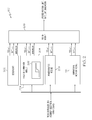
- FIG. 1 depicts a functional block diagram of an electromechanical actuator (EMA)-based effector control system according to an exemplary embodiment of the present invention
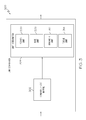
- FIG. 2 depicts a functional block diagram of an exemplary effector health management system that may be used to implement the system of FIG. 1 ;
- FIG. 3 depicts a block diagram of a limit computation function implemented in the effector health management system of FIG. 2 ;
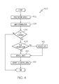
- FIG. 4 is a flowchart depicting a process implemented in the effector health management system of FIG. 2 .
- FIG. 1 an embodiment of an exemplary electromechanical actuator (EMA)-based effector control system 100 is depicted.
- the system 100 which may be used to control the movement of one or more control effectors.
- suitable control effectors include one or more flight control surfaces, one or more thrust reverser system components, one or more valves, or any one of numerous other devices, includes an electromechanical actuator (EMA) assembly 102 and a controller 120.
- EMA electromechanical actuator
- the system 100 is depicted and described as including only a single EMA 102 and a single controller 120, this is done merely for clarity and ease of depiction and description.
- the system 100 may be implemented with more than one EMA 102 and, if needed or desired, more than one controller 120.
- the EMA assembly 102 includes a power drive unit 104, an actuator 106, and a plurality of position sensors 108, 110.
- the power drive unit 104 is preferably implemented as a motor 104 and, at least in the depicted embodiment, is coupled to the actuator via a gearbox 112.
- the motor 104 is preferably implemented an electric motor, and may be any one of numerous types of AC or DC motors now known or developed in the future including, for example, an AC induction motor or a brushed DC motor. In a preferred embodiment, however, the motor 104 is implemented as a brushless DC motor.
- the motor 104 is configured, upon being properly energized and supplied with actuation position control signals, to rotate and supply a drive torque to the actuator 106 via the gearbox 112. It will be appreciated that the actuator assembly 102 may, in some embodiments, be eliminated.
- the actuator 106 includes an actuation member 114, which is coupled to receive the drive torque from the motor 104 and gearbox 112, and a translation member 116. In response to the drive torque supplied from the motor 104 and gearbox 112, the actuation member 114 rotates.
- the translation member 116 is coupled to the actuation member 114 and is configured, upon rotation thereof, to translate to a position. It may be seen that the actuation member 114 and the translation member 116, at least in the depicted embodiment, are implemented as a ballscrew assembly, in which the ballscrew functions as the actuation member 114 and the ballnut functions as the translation member 116.
- actuation member 114 and translation member 116 could be implemented as any one of numerous assemblies that convert rotational motion into translational motion including, for example, jackscrew assemblies and rollerscrew assemblies, just to name a few.
- EMA assembly 102 could be implemented as any one of numerous other types of EMAs including, but not limited to, numerous types of rotary actuators and/or numerous types of linear actuators, just to name a few.
- the position sensors include a first position sensor and a second position sensor 108, 110, respectively.
- the first position sensor 108 is coupled to, and is configured to supply a position signal representative of the position of, the translation member 116.
- the first position sensor 108 is implemented using a linear variable differential transformer (LVDT) type of position sensor, though any one of numerous other types of sensors may also be used. Additional translational and rotational sensors may be coupled to the non-illustrated control effector(s) to sense the position of the effector(s).
- LVDT linear variable differential transformer
- the second position sensor 110 is coupled to the motor rotor. Thus, when the motor 104 rotates the second position sensor 110 also rotates and supplies a position signal representative of the rotational position of the motor 104. It will be appreciated that the motor rotational signals are used, in some embodiments, to properly commutate the motor 104. Moreover, the motor rotational signals are also representative of the position of the translational member 116.
- the second position sensor 110 at least in the depicted embodiment, is implemented using a resolver, though it may also be implemented using any one of numerous other types of suitable sensors. No matter the particular types of position sensors that are used, the position signals from each of the position sensors 108, 110, are preferably supplied to the controller 120.
- the controller 120 supplies actuation position control signals to the motor 104 and, as was just mentioned, receives position signals from each of the position sensors 108, 110.
- the controller 120 is configured to receive external control signals from one or more external sources (not shown in FIG. 1 ).
- the controller 120 supplies actuation position control signals to the motor 104, which causes the motor 104 to be appropriately energized from an electric power source 115, to thereby rotate in the direction that will cause the translation member 116 to move to a desired position.
- the controller 120 using the position signals as feedback, properly commutates the motor 104 and implements a closed-loop control law to move the translation member 116 to the desired position.
- additional health management and control sensors may be associated with the EMA assembly 102 and/or control effector, if needed or desired.
- the EMA assembly 102 may have associated therewith one or more temperature sensors 118, one or more motor current sensors 122, one or more voltage sensors 124, and one or more bearing accelerometers 126, just to name a few.
- these sensors may be used to provide enhanced health status information for the EMA assembly 102.
- the control system 100 is coupled to, or is otherwise in operable communication with, an effector health management system 150, and may additionally be coupled to a vehicle (or system) controller 160.
- the effector health management system 150 which is also in operable communication with the vehicle controller 160, is configured to determine and supply health status information for the EMA assembly 102 and/or control effector(s) to the EMA controller 120 and/or the vehicle controller 160.
- the control law implemented in the controller 120 may be influenced, either directly or indirectly, by the health status information supplied by the effector health management system 150.
- FIG. 2 A more detailed functional block diagram of the effector health management system 150 is depicted in FIG. 2 , and with reference thereto will now be described in more detail.
- the effector health management system 150 includes memory 202, a fault determination module 204, and a fusion module 206.
- the memory 202 stores various numbers and types of data. Including among these stored data are data representative of the design position limit, the design rate limit, and the design bandwidth of the EMA assembly 102.
- the memory 202 may also, in some embodiments, store a design torque limit of the EMA assembly 102.
- the design position limit corresponds to the fully-extended position to which the EMA assembly 102 was designed to be moved.
- the design rate limit corresponds to the maximum rate at which the EMA assembly 102 was designed to move.
- the design bandwidth is related to the design frequency response of the EMA assembly 102.
- the EMA assembly 102 upon initial installation in the system 100, may be moved, if needed or desired, to a position that corresponds to the design position limit, and may be moved to the design position limit (or any other position, for that matter) at a rate that corresponds to the design rate limit. Moreover, the EMA assembly 102 will exhibit a frequency response that corresponds to the design bandwidth.
- the fault determination module 204 is in operable communication with the EMA assembly 102 and is configured to determine whether the EMA assembly 102 has experienced a fault.
- the fault determination module 204 is additionally configured, if it determines that the EMA assembly 102 has experienced a fault, to determine at least a fault-based position limit and a fault-based rate limit of the EMA assembly 102.
- the fault determination module 204 may additionally be configured to determine a fault-based bandwidth.
- the fault determination module 204 may also be configured to determine a fault-based torque limit.
- the fault determination module 204 may be variously configured to implement its functionality.
- the fault determination module 204 includes, among other functions, a software model 205 of the EMA assembly 102.
- the fault determination model 204, and more specifically the EMA assembly software model 205 is coupled to receive the same actuation position control signals that are supplied to the EMA assembly 102.
- the fault determination module 204 is additionally coupled to receive data representative of the response of the EMA assembly 102 to the actuation position control signals.
- the EMA software model 205 may receive the position signals from the first and second position sensors 108, 110.
- the EMA software model 250 may also receive sensor signals from one or more of the above-mentioned additional sensors 118-126, if included.
- the fault determination module 204 compares the response of the EMA assembly 102 and the response of the EMA assembly software model 205 and, based on this comparison, determines if the EMA assembly 102 has experienced a fault. In particular, if the comparison indicates that the EMA assembly 102 is not responding consistent with the EMA assembly software model 205, this indicates that the EMA assembly 102 has likely experienced some type of a fault.
- the particular types of faults that the EMA assembly 102 may potentially experience may vary.
- the EMA assembly 102 could experience a broken linkage, a stuck actuator, bad EMA subassemblies such as one or more failed bearings, a failed ballscrew, a failed gearbox, and a failed motor, just to name a few.
- the fault determination module 204 upon determining that the EMA assembly 102 has experienced a fault, causes an appropriate test signal to be transmitted to the EMA assembly 102 in order to confirm the presence of the fault. This confirmation also improves the accuracy of the fault-based position, rate, and/or bandwidth limits.
- test signal that is transmitted to the EMA assembly 102 may be generated and supplied directly from the fault determination module 204, or the fault determination module 204 may request a separate device, such as the fusion module 206, the controller 120, or the vehicle controller 160, to supply the appropriate test signal.
- the manner in which the particular faults are determined may also vary.
- the faults may be determined via various built-in test (BIT) procedures, which may supply BIT data to the system 150.
- the system 150 may determine various faults from the various sensor data and command data supplied thereto.
- a stuck actuator assembly fault may be determined if the measured effector position does not change in response to a command and/or if the value of the measured electrical load, in response to a command, is substantially greater than the estimated load for the same command.
- a position-limited actuator assembly fault may be determined if the measured effector/actuator position prematurely plateaus before reaching the commanded position and/or if the value of the measured electrical load, in response to a command, is substantially greater than the estimated load for the same command.
- a rate-limited actuator assembly fault may be determined if a calculated value of effector/actuator assembly movement rate is less than a threshold movement rate value.
- a torque-limited actuator assembly fault may be determined if the value of the measured electrical current, in response to a command, is substantially greater than the estimated current for the same command. It will be appreciated that these fault determination methods are merely exemplary, and are in no way meant to be inclusive of the exhaustive methods for determining the existence of various faults.
- the fault determination module 204 within or in addition to the software model 205, implements a limit computation function 300.
- the limit computation function 300 itself implements a condition-effects mapping function 302 and a limit determination function 304.
- the condition-effects mapping function 302 receives various types of data and, based on these data, determines which of the above-describe limits (e.g., position, rate, bandwidth, torque) need to be evaluated/reevaluated.
- the types of data it receives may vary, but in the depicted embodiment the data include sensor data from the each of the sensors 108, 110, 118-126, as well as various other non-illustrated health management and control sensors, various built-in test (BIT) data, and data from the above-mentioned software model 205, just to name a few.
- the condition-effects mapping function 302 determines if one or more faults are present and, using predetermined mapping, determine which limits need to be evaluated/reevaluated, and informs the limit determination function 304.
- the limit determination function 304 determines the appropriate limits. As such, the limit determination function implements a position limit determination function 306, a rate limit determination function 308, a bandwidth limit determination function 312, and (at least in some embodiments) a torque limit determination function 314.
- the manner in which each limit determination function 306-314 determines the associated limits may vary, from the relatively complex to the less complex. For example, if the EMA assembly 102 is supplied with a command that is less than one of the present limits, and the EMA assembly 102 or effector response to this command is less than the command, then the new limit will be set to the response.
- the fusion module 206 is in operable communication with the memory 202 and the fault determination module 204.
- the fusion module 204 may thus receive the design position, rate, and bandwidth limits from the memory 202, and the fault-based position, rate, and bandwidth limits from the fault determination module 204.
- the fusion module 206 upon receipt of the design limits and the fault-based limits, determines, as appropriate, updated position, rate, and bandwidth limits of the EMA assembly 102.
- the updated position, rate, and bandwidth limits are supplied to the controller 120 so that the control law (or laws) implemented in the controller 120 may be updated as needed to compensate for the updated limits, and so that the EMA assembly 102 may be controlled based on the updated limits.
- the effector health management system 150 may additionally include a power monitor module 208 and a temperature monitor module 212.
- the power monitor module 208 is in operable communication with the EMA assembly 102, and is configured to determine whether the EMA assembly 102 has experienced electric power degradation.
- the power monitor module 208 is also configured, if the EMA assembly 102 has experienced electric power degradation, to determine what are referred to herein as a degradation-based position limit and a degradation-based rate limit of the EMA assembly 102.
- the power monitor module 208 may be variously configured to implement the above-described function. In the depicted embodiment, however, the power monitor module 208 is coupled to receive a signal representative of an electrical characteristic of the electrical power source 115. The power monitor module 208, in response to this signal, determines whether the EMA assembly 102 has experienced electric power degradation. For example, if either or both the voltage or current (power) capabilities of the electrical power source 115 have degraded, then the torque capability of the EMA assembly 102, and hence the position and/or rate limits associated with the EMA assembly 102, may also degrade. Preferably, the power monitor module 208 is configured to also implement the limit computation function 300 depicted in FIG. 3 and described above.
- the temperature monitor module 212 is also in operable communication with the EMA assembly 102. More specifically, it is preferably coupled to receive one or more temperature signals from the above-noted one or more temperature sensors 118 that are representative of the temperature of the EMA assembly 102. The temperature monitor module 212 is further configured, upon receipt of the one or more temperature signals, to determine what are referred to herein as temperature-based position limit and a temperature-based rate limit of the EMA assembly 102. For example, if the temperature of the EMA assembly 102 increases, and approaches the operational limit for the motor, the motor drive, or various components, the magnitude of the current supplied to the EMA assembly 102 may need to be reduced, which may adversely impact the EMA position and/or rate limits. As with the power monitor module 208, the temperature monitor module 212 is also preferably configured to implement the limit computation function 300 depicted in FIG. 3 and described above
- the fusion module 206 determines updated position, rate, and bandwidth limits from the design limits and the fault-based limits.
- the fusion module 206 is further configured to determine at least the updated position and rate limits of the EMA assembly additionally from the degradation-based position and rate limits and the temperature-based position limit and rate limits.
- the fusion module 206 is additionally in operable communication with the power monitor module 208 and the temperature monitor module 212.
- the fusion module 206 may implement various methods and techniques for generating the updated position, rate, and bandwidth limits from the limits it receives from the fault determination module 204, the power monitor module 208, and the temperature monitor module 212.
- the fusion module 206 may implement a straight-forward logic scheme, in which the minimum limit supplied from each module is selected as the updated limit.
- the fusion module 206 may implement a fuzzy logic technique to determine the updated limits, or it may implement one or more other statistical-based techniques, which may include assigning various weights to the limits supplied from the fault determination module 204, the power monitor module 208, and the temperature monitor module 212.
- the updated limits are preferably supplied to the controller 120.
- the control law (or laws) implemented in the controller 120 are preferably updated, as needed, to compensate for the updated limits.
- the EMA assembly 102 is preferably controlled based on the updated limits.
- the updated limits may additionally be supplied to one or more other external devices or systems, informing these other devices or systems of the updated limits.
- the effector health management system 150 determines whether a fault has occurred 402. As was previously described, the effector health management system 150 may additionally determine the fault probability and severity. In any case, the system 150 thereafter determines appropriate limits (e.g., position, rate, bandwidth, and/or torque limits) 404 and whether one or more limits has changed 406..
- appropriate limits e.g., position, rate, bandwidth, and/or torque limits
- the system 150 determines whether the change in the limit(s) should be confirmed 408. If so, then an appropriate test is requested and initiated to so confirm the change 412. If no confirmation is needed, or after the change is confirmed, then the limit(s) is(are) updated 414, and the updated limits are reported 416 to the vehicle controller 160. The updated limits may also be reported, if needed or desired, to the EMA controller 120 and/or another non-illustrated external controller, such as a ground controller.
Landscapes
- Engineering & Computer Science (AREA)
- Physics & Mathematics (AREA)
- General Physics & Mathematics (AREA)
- Automation & Control Theory (AREA)
- Human Computer Interaction (AREA)
- Manufacturing & Machinery (AREA)
- Control Of Electric Motors In General (AREA)
- Manipulator (AREA)
- Numerical Control (AREA)
Applications Claiming Priority (1)
| Application Number | Priority Date | Filing Date | Title |
|---|---|---|---|
| US12/177,721 US7877231B2 (en) | 2008-07-22 | 2008-07-22 | Electromechanical actuator and effector health management system and method |
Publications (3)
| Publication Number | Publication Date |
|---|---|
| EP2148257A2 true EP2148257A2 (de) | 2010-01-27 |
| EP2148257A3 EP2148257A3 (de) | 2013-03-27 |
| EP2148257B1 EP2148257B1 (de) | 2020-02-12 |
Family
ID=41168677
Family Applications (1)
| Application Number | Title | Priority Date | Filing Date |
|---|---|---|---|
| EP09164837.8A Active EP2148257B1 (de) | 2008-07-22 | 2009-07-07 | Gesundheitsmanagementsystem und Verfahren für ein elektromechanisches Stellglied |
Country Status (3)
| Country | Link |
|---|---|
| US (1) | US7877231B2 (de) |
| EP (1) | EP2148257B1 (de) |
| JP (1) | JP5308261B2 (de) |
Cited By (4)
| Publication number | Priority date | Publication date | Assignee | Title |
|---|---|---|---|---|
| EP2444870A3 (de) * | 2010-10-22 | 2012-10-17 | Honeywell International Inc. | System und Verfahren zur Funktionszustandsbestimmung eines Steuerungseffektors |
| WO2014194104A1 (en) * | 2013-05-30 | 2014-12-04 | Eaton Corporation | Active impact force/torque control for an electromechanical actuator |
| DE102013009813A1 (de) * | 2013-06-12 | 2014-12-18 | Deutsches Zentrum für Luft- und Raumfahrt e.V. | Verfahren und System zur Detektion und ldentifikation eines vollständigen Verlusts der Steuerwirksamkeit einer Stellfläche in einem Flugsteuerungssystem eines Luftfahrzeugs |
| CN104865949A (zh) * | 2014-02-25 | 2015-08-26 | 霍尼韦尔国际公司 | 发起的测试健康管理系统和方法 |
Families Citing this family (7)
| Publication number | Priority date | Publication date | Assignee | Title |
|---|---|---|---|---|
| SE538281C2 (sv) * | 2013-10-22 | 2016-04-26 | Compacta Ab | Device for providing a volume of essentially sterile air |
| US9806639B2 (en) | 2015-04-29 | 2017-10-31 | General Electric Company | Dielectric fluids for linear switched capacitive devices |
| US10504656B2 (en) * | 2015-04-29 | 2019-12-10 | General Electric Company | Electrodes for linear switched capacitive devices |
| US9748867B2 (en) | 2015-08-03 | 2017-08-29 | General Electric Company | Control system for linear switched capacitive devices |
| CN106952028A (zh) * | 2017-03-13 | 2017-07-14 | 杭州安脉盛智能技术有限公司 | 机电装备故障预诊与健康管理方法及系统 |
| EP4163652A1 (de) * | 2021-10-05 | 2023-04-12 | Goodrich Actuation Systems Limited | Gesundheitsüberwachung eines elektrischen aktuators |
| US20240308648A1 (en) * | 2023-03-16 | 2024-09-19 | Honeywell International Inc. | Fly-by-wire flight control system with back-up control in an inceptor |
Family Cites Families (21)
| Publication number | Priority date | Publication date | Assignee | Title |
|---|---|---|---|---|
| GB8303324D0 (en) * | 1983-02-07 | 1983-03-09 | Secr Defence | Control systems |
| JP3166331B2 (ja) * | 1992-08-27 | 2001-05-14 | 株式会社デンソー | 故障診断装置 |
| JP3785585B2 (ja) * | 1997-03-25 | 2006-06-14 | カヤバ工業株式会社 | 電動式パワーステアリングシステムの異常検出制御装置 |
| US6298454B1 (en) * | 1999-02-22 | 2001-10-02 | Fisher-Rosemount Systems, Inc. | Diagnostics in a process control system |
| DE60136773D1 (de) * | 2000-06-16 | 2009-01-15 | Ntn Toyo Bearing Co Ltd | Überwachungs-, Diagnose- und Verkaufssystem für Maschinenkomponenten |
| JP2002323410A (ja) * | 2001-04-25 | 2002-11-08 | Fuji Heavy Ind Ltd | 車両管理システム |
| US6847917B2 (en) * | 2001-05-24 | 2005-01-25 | Simmonds Precision Products, Inc. | Method and apparatus for selecting condition indicators in determining the health of a component |
| FI20011742L (fi) * | 2001-08-31 | 2003-03-01 | Metso Field Systems Oy | Menetelmä ja järjestelmä teollisuusprosessin säätöpiirin suorituskyvun analysoimiseksi |
| LU90840B1 (en) * | 2001-09-25 | 2003-03-26 | Delphi Tech Inc | Method for controlling the operation of a system sub-system or component |
| GB0127254D0 (en) * | 2001-11-13 | 2002-01-02 | Lucas Industries Ltd | Aircraft flight surface control system |
| US6823675B2 (en) * | 2002-11-13 | 2004-11-30 | General Electric Company | Adaptive model-based control systems and methods for controlling a gas turbine |
| US6892127B2 (en) * | 2003-02-28 | 2005-05-10 | General Electric Company | Methods and apparatus for assessing gas turbine engine damage |
| JP4521258B2 (ja) * | 2004-01-28 | 2010-08-11 | 日立オートモティブシステムズ株式会社 | レゾルバ/デジタル変換器及びこれを用いた制御システム |
| US7081729B2 (en) * | 2004-03-23 | 2006-07-25 | The Boeing Company | Variable-structure diagnostics approach achieving optimized low-frequency data sampling for EMA motoring subsystem |
| WO2006014997A1 (en) * | 2004-07-28 | 2006-02-09 | Hr Textron Inc. | Improved acceptance testing of actuators using backlash and stiction measurements |
| US7770842B2 (en) * | 2004-08-24 | 2010-08-10 | Honeywell International Inc. | Aircraft flight control surface actuation system communication architecture |
| JP2006096242A (ja) * | 2004-09-30 | 2006-04-13 | Toyota Motor Corp | 車両制御装置 |
| US7222048B2 (en) * | 2005-04-21 | 2007-05-22 | General Electric Company | Methods and systems for diagnosing machinery |
| US7283933B2 (en) * | 2006-02-22 | 2007-10-16 | The Boeing Company | Efficiency monitor |
| JP2007331716A (ja) * | 2006-06-19 | 2007-12-27 | Auto Network Gijutsu Kenkyusho:Kk | 車両用の電動シート |
| JP2008097363A (ja) * | 2006-10-12 | 2008-04-24 | Okuma Corp | 異常診断方法及びその装置 |
-
2008
- 2008-07-22 US US12/177,721 patent/US7877231B2/en active Active
-
2009
- 2009-07-07 EP EP09164837.8A patent/EP2148257B1/de active Active
- 2009-07-17 JP JP2009168673A patent/JP5308261B2/ja not_active Expired - Fee Related
Non-Patent Citations (1)
| Title |
|---|
| BLANKE, M. ET AL., CONTROL ENGINEERING PRACTICE, vol. 5, no. 5, 1 May 1997 (1997-05-01), pages 693 - 702 |
Cited By (9)
| Publication number | Priority date | Publication date | Assignee | Title |
|---|---|---|---|---|
| EP2444870A3 (de) * | 2010-10-22 | 2012-10-17 | Honeywell International Inc. | System und Verfahren zur Funktionszustandsbestimmung eines Steuerungseffektors |
| US9046891B2 (en) | 2010-10-22 | 2015-06-02 | Honeywell International Inc. | Control effector health capabilities determination reasoning system and method |
| WO2014194104A1 (en) * | 2013-05-30 | 2014-12-04 | Eaton Corporation | Active impact force/torque control for an electromechanical actuator |
| US9758236B2 (en) | 2013-05-30 | 2017-09-12 | Eaton Corporation | Active impact force/torque control for an electromechanical actuator |
| DE102013009813A1 (de) * | 2013-06-12 | 2014-12-18 | Deutsches Zentrum für Luft- und Raumfahrt e.V. | Verfahren und System zur Detektion und ldentifikation eines vollständigen Verlusts der Steuerwirksamkeit einer Stellfläche in einem Flugsteuerungssystem eines Luftfahrzeugs |
| DE102013009813B4 (de) * | 2013-06-12 | 2017-02-23 | Deutsches Zentrum für Luft- und Raumfahrt e.V. | Verfahren und System zur Detektion und ldentifikation eines vollständigen Verlusts der Steuerwirksamkeit einer Stellfläche in einem Flugsteuerungssystem eines Luftfahrzeugs |
| CN104865949A (zh) * | 2014-02-25 | 2015-08-26 | 霍尼韦尔国际公司 | 发起的测试健康管理系统和方法 |
| EP2911025A3 (de) * | 2014-02-25 | 2015-11-11 | Honeywell International Inc. | Initiiertes Testgesundheitsverwaltungssystem und -verfahren |
| US9915925B2 (en) | 2014-02-25 | 2018-03-13 | Honeywell International Inc. | Initiated test health management system and method |
Also Published As
| Publication number | Publication date |
|---|---|
| US7877231B2 (en) | 2011-01-25 |
| EP2148257A3 (de) | 2013-03-27 |
| JP2010023831A (ja) | 2010-02-04 |
| US20100023301A1 (en) | 2010-01-28 |
| JP5308261B2 (ja) | 2013-10-09 |
| EP2148257B1 (de) | 2020-02-12 |
Similar Documents
| Publication | Publication Date | Title |
|---|---|---|
| US7877231B2 (en) | Electromechanical actuator and effector health management system and method | |
| US6241182B1 (en) | Hybrid control system for an aircraft aerodynamic surface | |
| US8604741B2 (en) | Secure monitoring and control device for aircraft piloting actuator | |
| KR101477275B1 (ko) | 주 조종 장치 | |
| US11319058B2 (en) | EMA thermal management optimization | |
| CN102046428A (zh) | 用于供电网络的开关模块和包括至少一个开关模块的供电网络 | |
| CN104619590A (zh) | 控制表面驱动组件 | |
| US7629763B2 (en) | Actuator assembly including a single axis of rotation locking member | |
| US7960934B2 (en) | Fault-tolerant control system | |
| EP3942208B1 (de) | Verfahren zum betrieb eines steuerventils, heizungs-, lüftungs- und klimaanlagen stellantrieb und computer programm produkt | |
| EP3005549B1 (de) | Aktive schockkraft/drehmoment regelung eines elektromagnetischen betätigungselements | |
| EP3531140B1 (de) | System und verfahren zur detektion von latenten fehlern in einer redundanten motoranwendung | |
| US10770994B2 (en) | Variable torque electric motor assembly | |
| AU2017295902B2 (en) | Control system and method for an electric actuator with fail-safe functionality | |
| EP4122818B1 (de) | System zur steuerung einer flugsteuerfläche | |
| US10742078B2 (en) | Variable torque electric motor assembly | |
| CN121395986A (zh) | 一种双电机多裕度伺服控制方法 | |
| WO2016038988A1 (ja) | 蒸気タービン、制御方法及びプログラム | |
| JP6687295B2 (ja) | 開閉装置 | |
| EP3477832A1 (de) | Elektromotoranordnung mit variablem drehmoment | |
| US20230352255A1 (en) | Control scheme for the operation of an electric motor actuator for a medium to high voltage circuit breaker | |
| Krishnamani et al. | Fault Tolerant Servo Actuation System using MRAC for Launch Vehicle Electromechanical Actuator |
Legal Events
| Date | Code | Title | Description |
|---|---|---|---|
| PUAI | Public reference made under article 153(3) epc to a published international application that has entered the european phase |
Free format text: ORIGINAL CODE: 0009012 |
|
| 17P | Request for examination filed |
Effective date: 20090707 |
|
| AK | Designated contracting states |
Kind code of ref document: A2 Designated state(s): AT BE BG CH CY CZ DE DK EE ES FI FR GB GR HR HU IE IS IT LI LT LU LV MC MK MT NL NO PL PT RO SE SI SK SM TR |
|
| AX | Request for extension of the european patent |
Extension state: AL BA RS |
|
| PUAL | Search report despatched |
Free format text: ORIGINAL CODE: 0009013 |
|
| AK | Designated contracting states |
Kind code of ref document: A3 Designated state(s): AT BE BG CH CY CZ DE DK EE ES FI FR GB GR HR HU IE IS IT LI LT LU LV MC MK MT NL NO PL PT RO SE SI SK SM TR |
|
| AX | Request for extension of the european patent |
Extension state: AL BA RS |
|
| RIC1 | Information provided on ipc code assigned before grant |
Ipc: G05B 19/4065 20060101AFI20130220BHEP Ipc: G05B 23/02 20060101ALI20130220BHEP Ipc: G05B 13/02 20060101ALI20130220BHEP |
|
| 17Q | First examination report despatched |
Effective date: 20130812 |
|
| RAP1 | Party data changed (applicant data changed or rights of an application transferred) |
Owner name: HONEYWELL INTERNATIONAL INC. |
|
| STAA | Information on the status of an ep patent application or granted ep patent |
Free format text: STATUS: EXAMINATION IS IN PROGRESS |
|
| GRAP | Despatch of communication of intention to grant a patent |
Free format text: ORIGINAL CODE: EPIDOSNIGR1 |
|
| STAA | Information on the status of an ep patent application or granted ep patent |
Free format text: STATUS: GRANT OF PATENT IS INTENDED |
|
| GRAS | Grant fee paid |
Free format text: ORIGINAL CODE: EPIDOSNIGR3 |
|
| INTG | Intention to grant announced |
Effective date: 20191113 |
|
| GRAJ | Information related to disapproval of communication of intention to grant by the applicant or resumption of examination proceedings by the epo deleted |
Free format text: ORIGINAL CODE: EPIDOSDIGR1 |
|
| GRAL | Information related to payment of fee for publishing/printing deleted |
Free format text: ORIGINAL CODE: EPIDOSDIGR3 |
|
| STAA | Information on the status of an ep patent application or granted ep patent |
Free format text: STATUS: EXAMINATION IS IN PROGRESS |
|
| GRAP | Despatch of communication of intention to grant a patent |
Free format text: ORIGINAL CODE: EPIDOSNIGR1 |
|
| STAA | Information on the status of an ep patent application or granted ep patent |
Free format text: STATUS: GRANT OF PATENT IS INTENDED |
|
| GRAA | (expected) grant |
Free format text: ORIGINAL CODE: 0009210 |
|
| STAA | Information on the status of an ep patent application or granted ep patent |
Free format text: STATUS: THE PATENT HAS BEEN GRANTED |
|
| INTC | Intention to grant announced (deleted) | ||
| INTG | Intention to grant announced |
Effective date: 20200103 |
|
| AK | Designated contracting states |
Kind code of ref document: B1 Designated state(s): AT BE BG CH CY CZ DE DK EE ES FI FR GB GR HR HU IE IS IT LI LT LU LV MC MK MT NL NO PL PT RO SE SI SK SM TR |
|
| REG | Reference to a national code |
Ref country code: GB Ref legal event code: FG4D |
|
| REG | Reference to a national code |
Ref country code: CH Ref legal event code: EP |
|
| REG | Reference to a national code |
Ref country code: AT Ref legal event code: REF Ref document number: 1232955 Country of ref document: AT Kind code of ref document: T Effective date: 20200215 |
|
| REG | Reference to a national code |
Ref country code: IE Ref legal event code: FG4D |
|
| REG | Reference to a national code |
Ref country code: DE Ref legal event code: R096 Ref document number: 602009061131 Country of ref document: DE |
|
| PG25 | Lapsed in a contracting state [announced via postgrant information from national office to epo] |
Ref country code: NO Free format text: LAPSE BECAUSE OF FAILURE TO SUBMIT A TRANSLATION OF THE DESCRIPTION OR TO PAY THE FEE WITHIN THE PRESCRIBED TIME-LIMIT Effective date: 20200512 Ref country code: FI Free format text: LAPSE BECAUSE OF FAILURE TO SUBMIT A TRANSLATION OF THE DESCRIPTION OR TO PAY THE FEE WITHIN THE PRESCRIBED TIME-LIMIT Effective date: 20200212 |
|
| REG | Reference to a national code |
Ref country code: LT Ref legal event code: MG4D |
|
| REG | Reference to a national code |
Ref country code: NL Ref legal event code: MP Effective date: 20200212 |
|
| PG25 | Lapsed in a contracting state [announced via postgrant information from national office to epo] |
Ref country code: IS Free format text: LAPSE BECAUSE OF FAILURE TO SUBMIT A TRANSLATION OF THE DESCRIPTION OR TO PAY THE FEE WITHIN THE PRESCRIBED TIME-LIMIT Effective date: 20200612 Ref country code: LV Free format text: LAPSE BECAUSE OF FAILURE TO SUBMIT A TRANSLATION OF THE DESCRIPTION OR TO PAY THE FEE WITHIN THE PRESCRIBED TIME-LIMIT Effective date: 20200212 Ref country code: SE Free format text: LAPSE BECAUSE OF FAILURE TO SUBMIT A TRANSLATION OF THE DESCRIPTION OR TO PAY THE FEE WITHIN THE PRESCRIBED TIME-LIMIT Effective date: 20200212 Ref country code: HR Free format text: LAPSE BECAUSE OF FAILURE TO SUBMIT A TRANSLATION OF THE DESCRIPTION OR TO PAY THE FEE WITHIN THE PRESCRIBED TIME-LIMIT Effective date: 20200212 Ref country code: BG Free format text: LAPSE BECAUSE OF FAILURE TO SUBMIT A TRANSLATION OF THE DESCRIPTION OR TO PAY THE FEE WITHIN THE PRESCRIBED TIME-LIMIT Effective date: 20200512 Ref country code: GR Free format text: LAPSE BECAUSE OF FAILURE TO SUBMIT A TRANSLATION OF THE DESCRIPTION OR TO PAY THE FEE WITHIN THE PRESCRIBED TIME-LIMIT Effective date: 20200513 |
|
| PG25 | Lapsed in a contracting state [announced via postgrant information from national office to epo] |
Ref country code: NL Free format text: LAPSE BECAUSE OF FAILURE TO SUBMIT A TRANSLATION OF THE DESCRIPTION OR TO PAY THE FEE WITHIN THE PRESCRIBED TIME-LIMIT Effective date: 20200212 |
|
| PG25 | Lapsed in a contracting state [announced via postgrant information from national office to epo] |
Ref country code: EE Free format text: LAPSE BECAUSE OF FAILURE TO SUBMIT A TRANSLATION OF THE DESCRIPTION OR TO PAY THE FEE WITHIN THE PRESCRIBED TIME-LIMIT Effective date: 20200212 Ref country code: DK Free format text: LAPSE BECAUSE OF FAILURE TO SUBMIT A TRANSLATION OF THE DESCRIPTION OR TO PAY THE FEE WITHIN THE PRESCRIBED TIME-LIMIT Effective date: 20200212 Ref country code: SK Free format text: LAPSE BECAUSE OF FAILURE TO SUBMIT A TRANSLATION OF THE DESCRIPTION OR TO PAY THE FEE WITHIN THE PRESCRIBED TIME-LIMIT Effective date: 20200212 Ref country code: RO Free format text: LAPSE BECAUSE OF FAILURE TO SUBMIT A TRANSLATION OF THE DESCRIPTION OR TO PAY THE FEE WITHIN THE PRESCRIBED TIME-LIMIT Effective date: 20200212 Ref country code: SM Free format text: LAPSE BECAUSE OF FAILURE TO SUBMIT A TRANSLATION OF THE DESCRIPTION OR TO PAY THE FEE WITHIN THE PRESCRIBED TIME-LIMIT Effective date: 20200212 Ref country code: PT Free format text: LAPSE BECAUSE OF FAILURE TO SUBMIT A TRANSLATION OF THE DESCRIPTION OR TO PAY THE FEE WITHIN THE PRESCRIBED TIME-LIMIT Effective date: 20200705 Ref country code: LT Free format text: LAPSE BECAUSE OF FAILURE TO SUBMIT A TRANSLATION OF THE DESCRIPTION OR TO PAY THE FEE WITHIN THE PRESCRIBED TIME-LIMIT Effective date: 20200212 Ref country code: CZ Free format text: LAPSE BECAUSE OF FAILURE TO SUBMIT A TRANSLATION OF THE DESCRIPTION OR TO PAY THE FEE WITHIN THE PRESCRIBED TIME-LIMIT Effective date: 20200212 Ref country code: ES Free format text: LAPSE BECAUSE OF FAILURE TO SUBMIT A TRANSLATION OF THE DESCRIPTION OR TO PAY THE FEE WITHIN THE PRESCRIBED TIME-LIMIT Effective date: 20200212 |
|
| PGFP | Annual fee paid to national office [announced via postgrant information from national office to epo] |
Ref country code: DE Payment date: 20200729 Year of fee payment: 12 Ref country code: GB Payment date: 20200724 Year of fee payment: 12 Ref country code: FR Payment date: 20200728 Year of fee payment: 12 |
|
| REG | Reference to a national code |
Ref country code: DE Ref legal event code: R097 Ref document number: 602009061131 Country of ref document: DE |
|
| REG | Reference to a national code |
Ref country code: AT Ref legal event code: MK05 Ref document number: 1232955 Country of ref document: AT Kind code of ref document: T Effective date: 20200212 |
|
| PLBE | No opposition filed within time limit |
Free format text: ORIGINAL CODE: 0009261 |
|
| STAA | Information on the status of an ep patent application or granted ep patent |
Free format text: STATUS: NO OPPOSITION FILED WITHIN TIME LIMIT |
|
| 26N | No opposition filed |
Effective date: 20201113 |
|
| PG25 | Lapsed in a contracting state [announced via postgrant information from national office to epo] |
Ref country code: IT Free format text: LAPSE BECAUSE OF FAILURE TO SUBMIT A TRANSLATION OF THE DESCRIPTION OR TO PAY THE FEE WITHIN THE PRESCRIBED TIME-LIMIT Effective date: 20200212 Ref country code: AT Free format text: LAPSE BECAUSE OF FAILURE TO SUBMIT A TRANSLATION OF THE DESCRIPTION OR TO PAY THE FEE WITHIN THE PRESCRIBED TIME-LIMIT Effective date: 20200212 |
|
| PG25 | Lapsed in a contracting state [announced via postgrant information from national office to epo] |
Ref country code: MC Free format text: LAPSE BECAUSE OF FAILURE TO SUBMIT A TRANSLATION OF THE DESCRIPTION OR TO PAY THE FEE WITHIN THE PRESCRIBED TIME-LIMIT Effective date: 20200212 Ref country code: SI Free format text: LAPSE BECAUSE OF FAILURE TO SUBMIT A TRANSLATION OF THE DESCRIPTION OR TO PAY THE FEE WITHIN THE PRESCRIBED TIME-LIMIT Effective date: 20200212 Ref country code: PL Free format text: LAPSE BECAUSE OF FAILURE TO SUBMIT A TRANSLATION OF THE DESCRIPTION OR TO PAY THE FEE WITHIN THE PRESCRIBED TIME-LIMIT Effective date: 20200212 |
|
| REG | Reference to a national code |
Ref country code: CH Ref legal event code: PL |
|
| REG | Reference to a national code |
Ref country code: BE Ref legal event code: MM Effective date: 20200731 |
|
| PG25 | Lapsed in a contracting state [announced via postgrant information from national office to epo] |
Ref country code: CH Free format text: LAPSE BECAUSE OF NON-PAYMENT OF DUE FEES Effective date: 20200731 Ref country code: IE Free format text: LAPSE BECAUSE OF NON-PAYMENT OF DUE FEES Effective date: 20200707 Ref country code: LI Free format text: LAPSE BECAUSE OF NON-PAYMENT OF DUE FEES Effective date: 20200731 Ref country code: LU Free format text: LAPSE BECAUSE OF NON-PAYMENT OF DUE FEES Effective date: 20200707 |
|
| PG25 | Lapsed in a contracting state [announced via postgrant information from national office to epo] |
Ref country code: BE Free format text: LAPSE BECAUSE OF NON-PAYMENT OF DUE FEES Effective date: 20200731 |
|
| REG | Reference to a national code |
Ref country code: DE Ref legal event code: R119 Ref document number: 602009061131 Country of ref document: DE |
|
| GBPC | Gb: european patent ceased through non-payment of renewal fee |
Effective date: 20210707 |
|
| PG25 | Lapsed in a contracting state [announced via postgrant information from national office to epo] |
Ref country code: GB Free format text: LAPSE BECAUSE OF NON-PAYMENT OF DUE FEES Effective date: 20210707 Ref country code: DE Free format text: LAPSE BECAUSE OF NON-PAYMENT OF DUE FEES Effective date: 20220201 |
|
| PG25 | Lapsed in a contracting state [announced via postgrant information from national office to epo] |
Ref country code: TR Free format text: LAPSE BECAUSE OF FAILURE TO SUBMIT A TRANSLATION OF THE DESCRIPTION OR TO PAY THE FEE WITHIN THE PRESCRIBED TIME-LIMIT Effective date: 20200212 Ref country code: MT Free format text: LAPSE BECAUSE OF FAILURE TO SUBMIT A TRANSLATION OF THE DESCRIPTION OR TO PAY THE FEE WITHIN THE PRESCRIBED TIME-LIMIT Effective date: 20200212 Ref country code: FR Free format text: LAPSE BECAUSE OF NON-PAYMENT OF DUE FEES Effective date: 20210731 Ref country code: CY Free format text: LAPSE BECAUSE OF FAILURE TO SUBMIT A TRANSLATION OF THE DESCRIPTION OR TO PAY THE FEE WITHIN THE PRESCRIBED TIME-LIMIT Effective date: 20200212 |
|
| PG25 | Lapsed in a contracting state [announced via postgrant information from national office to epo] |
Ref country code: MK Free format text: LAPSE BECAUSE OF FAILURE TO SUBMIT A TRANSLATION OF THE DESCRIPTION OR TO PAY THE FEE WITHIN THE PRESCRIBED TIME-LIMIT Effective date: 20200212 |
|
| P01 | Opt-out of the competence of the unified patent court (upc) registered |
Effective date: 20230525 |