EP2148346B1 - Manipulateur de conduite de véhicule - Google Patents
Manipulateur de conduite de véhicule Download PDFInfo
- Publication number
- EP2148346B1 EP2148346B1 EP09166105.8A EP09166105A EP2148346B1 EP 2148346 B1 EP2148346 B1 EP 2148346B1 EP 09166105 A EP09166105 A EP 09166105A EP 2148346 B1 EP2148346 B1 EP 2148346B1
- Authority
- EP
- European Patent Office
- Prior art keywords
- handle
- touch button
- control according
- plane
- head
- Prior art date
- Legal status (The legal status is an assumption and is not a legal conclusion. Google has not performed a legal analysis and makes no representation as to the accuracy of the status listed.)
- Active
Links
Images


Classifications
-
- B—PERFORMING OPERATIONS; TRANSPORTING
- B61—RAILWAYS
- B61C—LOCOMOTIVES; MOTOR RAILCARS
- B61C17/00—Arrangement or disposition of parts; Details or accessories not otherwise provided for; Use of control gear and control systems
- B61C17/12—Control gear; Arrangements for controlling locomotives from remote points in the train or when operating in multiple units
-
- H—ELECTRICITY
- H01—ELECTRIC ELEMENTS
- H01H—ELECTRIC SWITCHES; RELAYS; SELECTORS; EMERGENCY PROTECTIVE DEVICES
- H01H9/00—Details of switching devices, not covered by groups H01H1/00 - H01H7/00
- H01H9/02—Bases, casings, or covers
- H01H9/06—Casing of switch constituted by a handle serving a purpose other than the actuation of the switch, e.g. by the handle of a vacuum cleaner
-
- B—PERFORMING OPERATIONS; TRANSPORTING
- B60—VEHICLES IN GENERAL
- B60L—PROPULSION OF ELECTRICALLY-PROPELLED VEHICLES; SUPPLYING ELECTRIC POWER FOR AUXILIARY EQUIPMENT OF ELECTRICALLY-PROPELLED VEHICLES; ELECTRODYNAMIC BRAKE SYSTEMS FOR VEHICLES IN GENERAL; MAGNETIC SUSPENSION OR LEVITATION FOR VEHICLES; MONITORING OPERATING VARIABLES OF ELECTRICALLY-PROPELLED VEHICLES; ELECTRIC SAFETY DEVICES FOR ELECTRICALLY-PROPELLED VEHICLES
- B60L3/00—Electric devices on electrically-propelled vehicles for safety purposes; Monitoring operating variables, e.g. speed, deceleration or energy consumption
- B60L3/02—Dead-man's devices
-
- B—PERFORMING OPERATIONS; TRANSPORTING
- B61—RAILWAYS
- B61D—BODY DETAILS OR KINDS OF RAILWAY VEHICLES
- B61D49/00—Other details
-
- H—ELECTRICITY
- H01—ELECTRIC ELEMENTS
- H01H—ELECTRIC SWITCHES; RELAYS; SELECTORS; EMERGENCY PROTECTIVE DEVICES
- H01H25/00—Switches with compound movement of handle or other operating part
- H01H25/04—Operating part movable angularly in more than one plane, e.g. joystick
-
- B—PERFORMING OPERATIONS; TRANSPORTING
- B60—VEHICLES IN GENERAL
- B60L—PROPULSION OF ELECTRICALLY-PROPELLED VEHICLES; SUPPLYING ELECTRIC POWER FOR AUXILIARY EQUIPMENT OF ELECTRICALLY-PROPELLED VEHICLES; ELECTRODYNAMIC BRAKE SYSTEMS FOR VEHICLES IN GENERAL; MAGNETIC SUSPENSION OR LEVITATION FOR VEHICLES; MONITORING OPERATING VARIABLES OF ELECTRICALLY-PROPELLED VEHICLES; ELECTRIC SAFETY DEVICES FOR ELECTRICALLY-PROPELLED VEHICLES
- B60L2200/00—Type of vehicles
- B60L2200/26—Rail vehicles
-
- G—PHYSICS
- G05—CONTROLLING; REGULATING
- G05G—CONTROL DEVICES OR SYSTEMS INSOFAR AS CHARACTERISED BY MECHANICAL FEATURES ONLY
- G05G9/00—Manually-actuated control mechanisms provided with one single controlling member co-operating with two or more controlled members, e.g. selectively, simultaneously
- G05G9/02—Manually-actuated control mechanisms provided with one single controlling member co-operating with two or more controlled members, e.g. selectively, simultaneously the controlling member being movable in different independent ways, movement in each individual way actuating one controlled member only
- G05G9/04—Manually-actuated control mechanisms provided with one single controlling member co-operating with two or more controlled members, e.g. selectively, simultaneously the controlling member being movable in different independent ways, movement in each individual way actuating one controlled member only in which movement in two or more ways can occur simultaneously
- G05G9/047—Manually-actuated control mechanisms provided with one single controlling member co-operating with two or more controlled members, e.g. selectively, simultaneously the controlling member being movable in different independent ways, movement in each individual way actuating one controlled member only in which movement in two or more ways can occur simultaneously the controlling member being movable by hand about orthogonal axes, e.g. joysticks
- G05G2009/04774—Manually-actuated control mechanisms provided with one single controlling member co-operating with two or more controlled members, e.g. selectively, simultaneously the controlling member being movable in different independent ways, movement in each individual way actuating one controlled member only in which movement in two or more ways can occur simultaneously the controlling member being movable by hand about orthogonal axes, e.g. joysticks with additional switches or sensors on the handle
-
- H—ELECTRICITY
- H01—ELECTRIC ELEMENTS
- H01H—ELECTRIC SWITCHES; RELAYS; SELECTORS; EMERGENCY PROTECTIVE DEVICES
- H01H9/00—Details of switching devices, not covered by groups H01H1/00 - H01H7/00
- H01H9/02—Bases, casings, or covers
- H01H9/06—Casing of switch constituted by a handle serving a purpose other than the actuation of the switch, e.g. by the handle of a vacuum cleaner
- H01H2009/066—Casing of switch constituted by a handle serving a purpose other than the actuation of the switch, e.g. by the handle of a vacuum cleaner having switches mounted on a control handle, e.g. gear shift lever
-
- H—ELECTRICITY
- H01—ELECTRIC ELEMENTS
- H01H—ELECTRIC SWITCHES; RELAYS; SELECTORS; EMERGENCY PROTECTIVE DEVICES
- H01H2300/00—Orthogonal indexing scheme relating to electric switches, relays, selectors or emergency protective devices covered by H01H
- H01H2300/026—Application dead man switch: power must be interrupted on release of operating member
-
- H—ELECTRICITY
- H01—ELECTRIC ELEMENTS
- H01H—ELECTRIC SWITCHES; RELAYS; SELECTORS; EMERGENCY PROTECTIVE DEVICES
- H01H2300/00—Orthogonal indexing scheme relating to electric switches, relays, selectors or emergency protective devices covered by H01H
- H01H2300/028—Application dead man switch, i.e. power being interrupted by panic reaction of operator, e.g. further pressing down push button
-
- Y—GENERAL TAGGING OF NEW TECHNOLOGICAL DEVELOPMENTS; GENERAL TAGGING OF CROSS-SECTIONAL TECHNOLOGIES SPANNING OVER SEVERAL SECTIONS OF THE IPC; TECHNICAL SUBJECTS COVERED BY FORMER USPC CROSS-REFERENCE ART COLLECTIONS [XRACs] AND DIGESTS
- Y10—TECHNICAL SUBJECTS COVERED BY FORMER USPC
- Y10T—TECHNICAL SUBJECTS COVERED BY FORMER US CLASSIFICATION
- Y10T74/00—Machine element or mechanism
- Y10T74/20—Control lever and linkage systems
- Y10T74/20207—Multiple controlling elements for single controlled element
-
- Y—GENERAL TAGGING OF NEW TECHNOLOGICAL DEVELOPMENTS; GENERAL TAGGING OF CROSS-SECTIONAL TECHNOLOGIES SPANNING OVER SEVERAL SECTIONS OF THE IPC; TECHNICAL SUBJECTS COVERED BY FORMER USPC CROSS-REFERENCE ART COLLECTIONS [XRACs] AND DIGESTS
- Y10—TECHNICAL SUBJECTS COVERED BY FORMER USPC
- Y10T—TECHNICAL SUBJECTS COVERED BY FORMER US CLASSIFICATION
- Y10T74/00—Machine element or mechanism
- Y10T74/20—Control lever and linkage systems
- Y10T74/20396—Hand operated
Definitions
- the invention relates to a driving manipulator of a vehicle, in particular a railway vehicle, and the corresponding maneuvering method, the driving manipulator comprising an integrated automatic control element of Automatic Standby Control Control (VACMA).
- VACMA Automatic Standby Control Control
- the driving devices of trains or trams installed aboard the driving cabs include a VACMA system of automatic standby control by maintaining support by which the vigilance of the driver is regularly monitored.
- the driver is required to maintain a control element, in the form of a manual button or a pedal for a period of between 15 and 60 seconds, and then to release it regularly for a period typically of 2 seconds to 5 seconds, in order to check that the driver is not asleep or even dead and to trigger in case of a lack of vigilance an emergency stop of the vehicle.
- a control element in the form of a manual button or a pedal for a period of between 15 and 60 seconds, and then to release it regularly for a period typically of 2 seconds to 5 seconds, in order to check that the driver is not asleep or even dead and to trigger in case of a lack of vigilance an emergency stop of the vehicle.
- the document EP 169 0820 A proposes to integrate the automatic standby control in the driving handle in traction and braking in the form of a touch key.
- the technical problem is to determine a geometric architecture of the assembly consisting of the handle and the tactile key that is ergonomic for a VACMA system.
- the subject of the invention is a driving manipulator of a vehicle comprising an automatic standby treatment device by holding support control and a lever arm able to move in a predetermined direction of operation with arranged on one end of the arm, a handle, outer shape adapted to the shape of the palm of a hand according to claim 1.
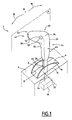
- a driving manipulator 2 according to the figures 1 , 2 and 3 is installed mobile relative to a support element 4 plane of a control panel installed in a cockpit.
- the driving manipulator 2 is able to be moved in a rotational movement in the two small amplitude directions contained in an extension travel plane P defined by a slideway 6.
- the slideway 6 is delimited by two walls 8, 10 each forming a disk portion.
- Each wall 8, 10 respectively comprises a straight edge 12, 14 forming a rope of the associated disk portion and resting on the support element 4.
- a direction of movement before, respectively rear, represented by the arrow 16, respectively the arrow 18 corresponds to a direction of actuation of the manipulator in traction of the vehicle, respectively of braking of the vehicle, an intermediate neutral position N being defined and corresponding to a absence of driving control.
- the pipe manipulator 2 comprises a lever arm 20 adapted to pivot about an axis 22 relative to the support member 4, and a handle 24, fitted on one end 26 of the lever arm 20 located on the side of the two walls 8, 10 of the slide 8.
- the handle 24 comprises a generally cylindrical base 28 extending along the axis of the lever arm 20 in which is fitted the end 26. It further comprises an ovoid-shaped head 30 surmounting the base and inclined relative to that and a touch sensitive touchpad 32.
- the angle a represented on the figure 2 formed by the extension plane of the support member 4 and the major axis of the ovoid-shaped head 30 is between 5 degrees and 85 degrees.
- the handle 24 comprises a solid shell 34 with five faces 40, 42, 44, 46, 48 including a top face 40 of the head 30, a front lateral face 42 facing the direction of displacement before 16, a rear lateral face 44. oriented towards the rearward movement direction 18, a left side face 46 facing to the left looking forward 16, a right side face 48 facing to the right looking forward 16.
- the left and right lateral faces 46, 48 are symmetrical with respect to a plane of symmetry Q parallel to the plane of displacement P and here confused with the latter.
- the faces 40, 42, 44, 46, 48 are regular surfaces smoothly connected by fillets.
- the top face 40 of the head is in its shape adapted to be touched flat by the palm of one hand and to be wound on its part connected to the front lateral face 42 by the fingers of the same hand, in particular the index, middle finger and little finger.
- the rear face 44 is in its shape on its head portion 30 connected to the top face 40 adapted to be pushed forward by the palm of hand.
- the front face 42 is adapted, by its shape, to its head portion 30 connected to the top face 40 to be pulled by the fingers, in particular the index finger towards the rear and adapted to be wound on its base portion 28 by the fingers in particular. the middle finger and the little finger.
- the touch sensitive touch pad 32 is disposed in a hole 50 drilled in the solid shell 34 forming the carrying structure of the handle 24 and fixedly fixed to the shell 34.
- the touch key 32 has a fixed touch surface 52 flush with the edge of the hole 50 forming an edge with the left lateral face 46 of the handle 24.
- the touch key 32 is preferably located at the left side face 46 or the right side face 48 of the handle.
- the case of an arrangement of the touch key 32 at the left side face 46, respectively at the right side face 48 corresponds to the case shown in FIG. figure 1 a station for the driver to the left of the manipulator then actuated by the right hand, respectively to the case not shown a station for the driver to the right of the manipulator then actuated by the left hand.
- the touch key 32 is located at the front side face 42 or the rear side face 44.
- the touch key 32 is located at a distance L from the plane of symmetry Q less than or equal to 25 mm.
- the distance H of the touch key to the plane of the support element is less than or equal to 95 mm.
- the touch key 32 is electrically connected by an electric cable 54 to a device 56 for automatic stand-by processing with support holding control
- the lever arm 20 and the handle 24 are hollow so as to provide a passage to the electrical cable 54 connected to the touch key 32, the passage being inaccessible from the outside when the manipulator is mounted on the support member.
- the manipulator 2 is removable from the support element 4.
- An automatic standby system 60 comprises the driving manipulator 2 described above and the automatic standby processing device 56 VACMA.
- the touch key 32 is coupled to a radiofrequency transmitter and the processing device 56 comprises a radio frequency receiver adapted to receive signals transmitted by the radiofrequency transmitter.
- the touch key 32 forms a capacitor whose fixed touch surface 52 constitutes an armature face, the capacitor having a variable capacitance as a function of the presence or absence of contact of the skin of a finger on the touch surface 52 of the key 32.
- the contact is ensured as soon as the finger touches or as soon as the finger presses the key 32 with a very low pressure without deforming it.
- the capacitance variation is conventionally measured by the application through the cable 54 and across the capacitor of a variable voltage supplied by an AC voltage source integrated into the processing device. and by measuring the current flowing in the series-connected impedance presented by the capacitor.
- the processing device 56 comprises an electromechanical relay or an electronic element, for example a transistor, capable of detecting a passage of current when the touch key 32 is pressed.
- the processing device 56 comprises an electromechanical relay or an electronic element, for example a transistor capable of detecting a power failure when the touch key is pressed.
- the processing device 56 is able to monitor the driver's compliance with the VACMA cycle and to check that the touch key is regularly kept in contact with at least one finger for a period of between 15 and 60 seconds followed by a release during a duration typically of 2 to 5 seconds. Thus, it is verified that the driver is not asleep or died and it is possible to trigger in case of a lack of vigilance an emergency stop of the vehicle.
- FIG. 4 On the figure 4 , a driving maneuver towards the front of the manipulator 2 is shown during which the driver of the vehicle is in the seated position and actuates the manipulator 2 with his right hand.
- the hand pushes the handle 24 by the palm of the thumb while the phalanges of the middle finger, the ring finger and the little finger roll up the base of the handle.
- the activation of the touch key 32 VACMA is implemented naturally by the terminal phalanx of the thumb which presses with minimal effort on the key. Similarly the release of the key is done with minimal muscle effort.
- This configuration is also ergonomic and applicable to the case of a maneuver to the rear.
- the hand is positioned in the same way with respect to the handle 24, only the part exerting the actuating force differing in that the phalanges back of the middle finger, ring finger and little finger exerting a thrust force of the handle backwards.
- This configuration is also ergonomic and applicable in the case of a lack of operation in the neutral position N of the manipulator.
- FIG. 4 a driving maneuver towards the front of the manipulator 2 is shown during which the driver is in a sitting position and actuates the manipulator with his right hand.
- the hand pushes the handle by the palm of the thumb while the phalanges of the middle finger, the ring finger and the little finger rolling the base of the handle.
- the activation of the touch key 32 VACMA is implemented naturally by the terminal phalanx of the thumb which presses with minimal effort on the key. Similarly the release of the key is done with minimal muscle effort.
- This configuration is also ergonomic and applicable to the case of a maneuver to the rear.
- the hand is positioned in the same way with respect to the handle, only the part exerting the actuating force differs in that the rear phalanges of the major, annular and atrial exerting a thrust force of the handle backwards.
- This configuration is also ergonomic and applicable in the case of a lack of operation in the neutral position N of the manipulator.
- FIG. 5 a driving maneuver towards the rear of the manipulator 2 is shown during which the driver is in a standing position and actuates the manipulator with his right hand.
- the hand pushes the handle back by the knuckles of the index finger, the rear phalanges of the middle finger and the ring finger, while the thumb is off the head of the handle backwards and the high.
- the knuckles of the index finger, the ring finger and the little finger roll up the base of the handle.
- the activation of the touch key 32 VACMA is implemented naturally by the terminal phalanx of the middle finger which presses with minimal effort on the key. In the same way the release of the key is done with a minimal muscular effort of the major.
- a driving maneuver forward 16 of the manipulator 2 is shown during which the driver is in a standing position and actuates the manipulator with his right hand.
- the hand pushes the handle 24 by the palm of the thumb and the finger pads, the set of finger phalanges except the thumb covering the head 30 of the handle 24 by the top face 40, the thumb knuckles winding the base 28 of the handle 24.
- the activation of the touch key VACMA is implemented naturally by the rear phalanx of the thumb which is pressed with minimal effort on the touch key 32. Similarly the release of the key 32 is done with minimal muscular effort.
- This configuration is also ergonomic and applicable in the case of a lack of operation in the neutral position N of the manipulator.
- the touch key 32 is disposed on the head 30 of ovoid shape at one of the two lateral faces, here the side face 46 parallel to the actuation plane P containing the actuating directions 14, 16 and the major axis of the head 30 shown in broken lines on the figure 2 .
- the axis traversing the touch key 32 perpendicularly to the lateral face 46 at which it is disposed intersects the actuating plane P at a point near or even belonging to the major axis of the head 30 of ovoid shape.
- the thumb of the hand remains ergonomically in contact with the touch key 32 without any detachment thereof during the transition.
- the twisting movement of the handle required during this transition is a minimal movement in terms of stroke and effort.
Landscapes
- Engineering & Computer Science (AREA)
- Transportation (AREA)
- Mechanical Engineering (AREA)
- Automation & Control Theory (AREA)
- Life Sciences & Earth Sciences (AREA)
- Sustainable Development (AREA)
- Sustainable Energy (AREA)
- Power Engineering (AREA)
- Mechanical Control Devices (AREA)
- Manipulator (AREA)
- Braking Elements And Transmission Devices (AREA)
Description
- L'invention se rapporte à un manipulateur de conduite d'un véhicule, notamment un véhicule ferroviaire, et le procédé de manoeuvre correspondant, le manipulateur de conduite comportant un élément intégré de commande de Veille Automatique par Contrôle de Maintien d'Appui (VACMA).
- Classiquement, les dispositifs de conduite de trains ou de tramways installés à bord des cabines de pilotage comportent un système VACMA de veille automatique par contrôle de maintien d'appui par lequel la vigilance du conducteur est régulièrement surveillée.
- Le conducteur est astreint à maintenir appuyé un élément de commande, sous forme d'un bouton manuel ou d'une pédale pendant une durée comprise entre 15 et 60 secondes, puis à le relâcher régulièrement pendant une durée typiquement de 2 secondes à 5 secondes, de manière à vérifier que le conducteur n'est pas endormi voire décédé et à déclencher dans le cas d'un défaut de vigilance un arrêt d'urgence du véhicule.
- Il est connu qu'une telle astreinte entraîne des contraintes de fatigue physique et psychique pour le conducteur pendant la conduite.
- Dans le but d'améliorer l'ergonomie liée à la conduite du véhicule et à l'activation de la commande de veille automatique, le document
EP 169 0820 A propose d'intégrer la commande veille automatique dans la poignée de conduite en traction et en freinage sous la forme d'une touche tactile. - Toutefois, le document ne décrit pas une architecture géométrique détaillée de l'ensemble poignée de conduite / touche tactile de commande de veille garantissant une ergonomie de qualité, c'est-à-dire entraînant un effort de tension / fléchissement musculaire minimal pour le conducteur.
- L'état de la technique le plus proche est le document
EP 1 400 426 révélant un manipulateur de conduite selon le préambule de la revendication 1. - Le problème technique est de déterminer une architecture géométrique de l'ensemble constitué par la poignée de conduite et de la touche tactile qui soit ergonomique pour un système VACMA.
- A cet effet, l'invention a pour objet un manipulateur de conduite d'un véhicule comprenant un dispositif de traitement de veille automatique par contrôle de maintien d'appui et un bras de levier apte à se déplacer selon une direction d'actionnement prédéterminée avec, disposé sur une extrémité du bras, une poignée, de forme externe adaptée à la forme de la paume d'une main selon la revendication 1.
- Suivant des modes particuliers de réalisation, le manipulateur de conduite comporte l'une ou plusieurs des caractéristiques suivantes :
- la poignée est symétrique par rapport à un plan de symétrie contenant la direction d'actionnement et la distance de la touche tactile au plan de symétrie est inférieur à 25 mm ;
- le manipulateur comprend un élément de support par rapport auquel la poignée est mobile et la poignée présente une position de référence dans laquelle le bras de levier est disposé normal par rapport au plan de l'élément de support et, dans la position de référence, la distance de la touche tactile à l'élément de support est inférieure ou égale à 95 mm ;
- la touche tactile est sensible au toucher ;
- l'angle a formé par le plan d'extension de l'élément support et le grand axe de la tête est compris entre 5 degrés et 85 degrés ;
- la poignée est creuse et la touche tactile est apte à être connecté électriquement à l'intérieur de la poignée par un câble électrique ;
- le bras de levier est creux de manière à fournir un passage à un câble électrique relié à la touche tactile, le passage étant inaccessible depuis l'extérieur ;
- le dispositif de traitement comprend un relais électromécanique ou un élément électronique apte à détecter un passage de courant lors d'un appui sur la touche tactile ; et
- le dispositif de traitement comprend un relais électromécanique ou un élément électronique apte à détecter une coupure de courant lors d'un appui sur la touche tactile.
- L'invention sera mieux comprise à la lecture de la description d'une unique forme de réalisation qui va suivre, donnée uniquement à titre d'exemple et faite en se référant aux dessins sur lesquels :
- la
Figure 1 est une vue en perspective d'un manipulateur de conduite selon l'invention, - la
Figure 2 est une vue latérale gauche du manipulateur de conduite de lafigure 1 , - la
Figure 3 est une vue arrière du manipulateur de conduite de lafigure 1 , - la
Figure 4 est une vue du positionnement d'une main d'un conducteur en position assise saisissant le manipulateur pendant une manoeuvre d'actionnement ou en l'absence de manoeuvre, - la
Figure 5 est une vue du positionnement d'une main d'un conducteur en position debout saisissant le manipulateur lors d'une manoeuvre d'actionnement vers l'arrière, - la
Figure 6 est une vue du positionnement d'une main d'un conducteur en position debout saisissant le manipulateur pendant une manoeuvre d'actionnement vers l'avant ou en l'absence de manoeuvre. - Un manipulateur de conduite 2 suivant les
figures 1 ,2 et3 est installé mobile par rapport à un élément support 4 plan d'un pupitre de conduite installé à bord d'une cabine de pilotage. - Le manipulateur de conduite 2 est apte à être déplacé selon un mouvement de rotation dans les deux sens de faible amplitude contenu dans un plan de course d'extension P défini par une glissière 6.
- La glissière 6 est délimitée par deux parois 8, 10 formant chacune une portion de disque. Chaque paroi 8, 10 comporte respectivement une tranche 12, 14 rectiligne formant une corde de la portion de disque associée et reposant sur l'élément de support 4.
- Un sens de mouvement avant, respectivement arrière, représenté par la flèche 16, respectivement la flèche 18 correspond à un sens d'actionnement du manipulateur en traction du véhicule, respectivement de freinage du véhicule, une position neutre N intermédiaire étant définie et correspondant à une absence de commande de conduite.
- Le manipulateur de conduite 2 comprend un bras de levier 20 apte à pivoter autour d'un axe 22 par rapport à l'élément de support 4, et une poignée 24, emmanchée sur une extrémité 26 du bras de levier 20 située du côté des deux parois 8, 10 de la glissière 8.
- La poignée 24 comprend une embase 28 généralement cylindrique s'étendant suivant l'axe du bras de levier 20 dans laquelle est emmanchée l'extrémité 26. Elle comprend en outre une tête 30 de forme ovoïde surmontant l'embase et inclinée par rapport à celle-ci, et une touche tactile sensible au toucher 32.
- L'angle a, représenté sur la
figure 2 , formé par le plan d'extension de l'élément support 4 et le grand axe de la tête 30 de forme ovoïde est compris entre 5 degrés et 85 degrés. - La poignée 24 comprend une coque solide 34 avec cinq faces 40, 42, 44, 46, 48 dont une face de dessus 40 de la tête 30, une face latérale avant 42 orientée vers le sens de déplacement avant 16, une face latérale arrière 44 orientée vers le sens de déplacement arrière 18, une face latérale gauche 46 située vers la gauche en regardant vers l'avant 16, une face latérale droite 48 située vers la droite en regardant vers l'avant 16.
- Les faces latérales gauche et droite 46, 48 sont symétriques par rapport à un plan de symétrie Q parallèle au plan de déplacement P et ici confondu avec ce dernier.
- Les faces 40, 42, 44, 46, 48 sont des surfaces régulières raccordées de manière lisse par des congés.
- La face de dessus 40 de la tête est par sa forme apte à être touchée à plat par la paume d'une main et à être enroulée sur sa partie raccordée à la face latérale avant 42 par les doigts de la même main, notamment l'index, le majeur et l'auriculaire.
- La face arrière 44 est par sa forme sur sa partie de tête 30 raccordée à la face de dessus 40 apte à être poussée vers l'avant par la paume de main.
- La face avant 42 est apte par sa forme sur sa partie de tête 30 raccordée à la face de dessus 40 à être tirée par les doigts notamment l'index vers l'arrière et apte à être enroulé sur sa partie embase 28 par les doigts notamment le majeur et l'auriculaire.
- La touche tactile 32 sensible au toucher est disposée dans un trou 50 percé dans la coque 34 solide formant la structure porteuse de la poignée 24 et fixé de manière inamovible à la coque 34.
- La touche tactile 32 comporte une surface tactile 52 fixe affleurant au niveau du bord du trou 50 formant arête avec la face latérale gauche 46 de la poignée 24.
- La touche tactile 32 est située préférentiellement au niveau de la face latérale gauche 46 ou de la face latérale droite 48 de la poignée.
- Le cas d'une disposition de la touche tactile 32 au niveau de la face latérale gauche 46, respectivement au niveau de la face latérale droite 48, correspond au cas représenté sur la
figure 1 d'un poste pour le conducteur situé à gauche du manipulateur alors actionnable par la main droite, respectivement au cas non représenté d'un poste pour le conducteur situé à droite du manipulateur alors actionnable par la main gauche. - En variante, la touche tactile 32 est située au niveau de la face latérale avant 42 ou de la face latérale arrière 44.
- La touche tactile 32 est située à une distance L du plan de symétrie Q inférieure ou égale à 25 mm.
- La distance H de la touche tactile au plan de l'élément de support est inférieure ou égale à 95 mm.
- La touche tactile 32 est connectée électriquement par un câble électrique 54 à un dispositif 56 de traitement de veille automatique à contrôle de maintien d'appui
- Le bras de levier 20 et la poignée 24 sont creux de manière à fournir un passage au câble électrique 54 relié à la touche tactile 32, le passage étant inaccessible depuis l'extérieur lorsque le manipulateur est monté sur l'élément de support.
- Le manipulateur 2 est démontable de l'élément de support 4.
- Un système de veille automatique 60 selon l'invention comprend le manipulateur de conduite 2 décrit ci-dessus et le dispositif de traitement 56 de veille automatique VACMA.
- Ainsi, l'accès aux éléments sensibles du système de veille automatique par contrôle de maintien d'appui lorsqu'il est installé, c'est-à-dire à la touche tactile 32, au câble électrique 54 et au dispositif de traitement 56 est protégé et toute tentative quelconque d'inhibition du système de veille 60 est ainsi empêchée.
- En variante, la touche tactile 32 est couplée à un émetteur radiofréquence et le dispositif de traitement 56 comprend un récepteur radiofréquence apte à recevoir des signaux émis par l'émetteur radiofréquence.
- La touche tactile 32 forme un condensateur dont la surface tactile 52 fixe constitue une face d'armature, le condensateur ayant une capacité variable en fonction de la présence ou non d'un contact de la peau d'un doigt sur la surface tactile 52 de la touche 32.
- Le contact est assuré dès que le doigt touche ou dès que le doigt appuie sur la touche 32 avec une très faible pression sans la déformer.
- La variation de capacité est mesurée de manière classique par l'application au travers du câble 54 et aux bornes du condensateur d'une tension variable fournie par une source de tension alternative intégrée au dispositif de traitement et par la mesure du courant circulant dans l'impédance montée en série présentée par le condensateur.
- Le dispositif de traitement 56 comprend un relais électromécanique ou un élément électronique, par exemple un transistor, apte à détecter un passage de courant lors d'un appui sur la touche tactile 32.
- En variante, le dispositif de traitement 56 comprend un relais électromécanique ou un élément électronique, par exemple un transistor apte à détecter une coupure de courant lors d'un appui sur la touche tactile.
- Le dispositif de traitement 56 est apte à surveiller le respect du cycle VACMA par le conducteur et à vérifier que la touche tactile est régulièrement maintenue en contact avec au moins un des doigt pendant une durée comprise entre 15 et 60 secondes suivi d'un relâchement pendant une durée typiquement de 2 à 5 secondes. Ainsi, il est vérifié que le conducteur n'est pas endormi voire décédé et il est possible de déclencher dans le cas d'un défaut de vigilance un arrêt d'urgence du véhicule.
- Sur la
figure 4 , une manoeuvre de conduite vers l'avant du manipulateur 2 est représentée pendant laquelle le conducteur du véhicule est en position assise et actionne le manipulateur 2 avec sa main droite. - Dans cette configuration, la main pousse la poignée 24 par la paume du pouce tandis les phalanges du majeur, de l'annulaire et de l'auriculaire enroulent l'embase de la poignée.
- L'activation de la touche tactile 32 VACMA est mise en oeuvre naturellement par la phalange terminale du pouce qui vient presser avec un effort minimal sur la touche. De même le relâchement de la touche se fait avec un effort musculaire minimal.
- L'exercice conjoint de la manoeuvre de conduite vers l'avant et l'activation de la veille automatique se fait également sans effort supplémentaire car aucune torsion du poignet n'est nécessaire, le plan défini par la poignée étant aligné avec le plan de course P du manipulateur.
- Cette configuration est également ergonomique et applicable au cas d'une manoeuvre vers l'arrière.
- La main est positionnée de la même façon par rapport à la poignée 24, seule la partie exerçant l'effort d'actionnement différant en ce que les phalanges arrière des majeur, annulaire et auriculaire exerçant un effort de poussée de la poignée vers l'arrière.
- Cette configuration est également ergonomique et applicable au cas d'une absence de manoeuvre dans la position neutre N du manipulateur.
- Sur la
figure 4 , une manoeuvre de conduite vers l'avant du manipulateur 2 est représentée pendant laquelle le conducteur est en position assise et actionne le manipulateur avec sa main droite. - Dans cette configuration, la main pousse la poignée par la paume du pouce tandis les phalanges du majeur, de l'annulaire et de l'auriculaire enroulant l'embase de la poignée.
- L'activation de la touche tactile 32 VACMA est mise en oeuvre naturellement par la phalange terminale du pouce qui vient presser avec un effort minimal sur la touche. De même le relâchement de la touche se fait avec un effort musculaire minimal.
- L'exercice conjoint de la manoeuvre de conduite vers l'avant et l'activation de la veille se fait également sans effort supplémentaire car aucune torsion du poignet n'est nécessaire, le plan défini par la poignée étant aligné avec le plan de course P du manipulateur.
- Cette configuration est également ergonomique et applicable au cas d'une manoeuvre vers l'arrière.
- La main est positionnée de la même façon par rapport à la poignée, seule la partie exerçant l'effort d'actionnement diffère en ce que les phalanges arrière des majeurs, annulaire et auriculaire exerçant un effort de poussée de la poignée vers l'arrière.
- Cette configuration est également ergonomique et applicable au cas d'une absence de manoeuvre dans la position neutre N du manipulateur.
- Sur la
figure 5 , une manoeuvre de conduite vers l'arrière du manipulateur 2 est représentée pendant laquelle le conducteur est en position debout et actionne le manipulateur avec sa main droite. - Dans cette configuration, la main pousse la poignée vers l'arrière par les phalanges de l'index, les phalanges arrière du majeur et de l'annulaire, tandis que le pouce est décollé de la tête de la poignée vers l'arrière et le haut. Les phalanges de l'index, de l'annulaire et de l'auriculaire enroulent l'embase de la poignée.
- L'activation de la touche tactile 32 VACMA est mise en oeuvre naturellement par la phalange terminale du majeur qui vient presser avec un effort minimal sur la touche. De même le relâchement de la touche se fait avec un effort musculaire minimal du majeur.
- L'exercice conjoint de la manoeuvre de conduite vers l'arrière et l'activation de la veille se fait également sans effort supplémentaire car aucune torsion du poignet n'est nécessaire, le plan défini par la poignée étant aligné avec le plan de course P du manipulateur.
- Sur la
figure 6 , une manoeuvre de conduite vers l'avant 16 du manipulateur 2 est représentée pendant laquelle le conducteur est en position debout et actionne le manipulateur avec sa main droite. - Dans cette configuration, la main pousse la poignée 24 par la paume du pouce et les coussinets des doigts, l'ensemble des phalanges de doigts hormis le pouce recouvrant la tête 30 de la poignée 24 par la face de dessus 40, les phalanges du pouce enroulant l'embase 28 de la poignée 24.
- L'activation de la touche tactile VACMA est mise en oeuvre naturellement par la phalange arrière du pouce qui vient presser avec un effort minimal sur la touche tactile 32. De même le relâchement de la touche 32 se fait avec un effort musculaire minimal.
- L'exercice conjoint de la manoeuvre de conduite vers l'arrière et l'activation de la veille se fait également sans effort supplémentaire car aucune torsion du poignet n'est nécessaire, le plan défini par la poignée étant aligné avec le plan de la face de dessus en étant légèrement cassé, ce qui correspond à une position de repos du poignet.
- Cette configuration est également ergonomique et applicable au cas d'une absence de manoeuvre dans la position neutre N du manipulateur.
- Suivant les
figures 1 ,2 ,3 ,4, 5, 6 , la touche tactile 32 est disposée sur la tête 30 de forme ovoïde au niveau d'une des deux faces latérales, ici la face latérale 46 parallèle au plan d'actionnement P contenant les directions d'actionnement 14, 16 et le grand axe de la tête 30 représenté en trait interrompu sur lefigure 2 . - L'axe traversant la touche tactile 32 perpendiculairement à la face latérale 46 au niveau de laquelle elle est disposée coupe le plan d'actionnement P en un point proche voire appartenant au grand axe de la tête 30 de forme ovoïde.
- Ainsi, lors d'une transition de la main entre le mode de conduite, décrit suivant la
figure 6 dans lequel la paume de la main est posée sur la face de dessus 40, et le mode de conduite, décrit suivant lafigure 4 dans lequel la paume pousse ou les phalanges tirent le manipulateur, le pouce de la main reste de manière ergonomique en contact avec la touche tactile 32 sans aucun décollement de celui-ci pendant la transition. Le mouvement de torsion de la poignée requis pendant cette transition est un mouvement minimal en termes de course et d'effort.
Claims (10)
- Manipulateur de conduite d'un véhicule comprenant :- un dispositif de traitement (56) de veille automatique par contrôle de maintien d'appui ;- un bras de levier (20) apte à se déplacer selon une direction d'actionnement prédéterminée (16, 18) ; ,- une poignée (24) disposée sur une extrémité (26) du bras (20) et de forme externe adaptée à la forme de la paume d'une main ;la poignée (24) comportant :une embase (28) généralement tubulaire s'étendant suivant l'axe du bras (20),une tête (30), surmontant l'embase (28), de forme ovoïde et de grand axe incliné par rapport à l'embase (28),une face de dessus (40) située sur la tête (30) et à l'opposé du bras de levier (20) par rapport à la poignée (24),au moins une face latérale (42, 44, 46, 48) globalement perpendiculaire la face de dessus (40), etune touche tactile (32) connectée électriquement au dispositif de traitement (56) de veille automatique par contrôle de maintien d'appui et disposée au niveau d'une face latérale (46, 48) parallèle au plan (P) d'actionnement contenant la direction d'actionnement (16, 18) et le grand axe de la tête (30),caractérisé en ce que la touche tactile (32) est située sur la tête (30) de forme ovoïde.
- Manipulateur de conduite selon la revendication 1, caractérisé en ce qu'un axe traversant la touche tactile (32) perpendiculairement à la face latérale (46, 48) au niveau de laquelle elle est disposée coupe le plan d'actionnement (P) en un point proche ou appartenant au grand axe de la tête (30).
- Manipulateur de conduite selon l'une des revendications 1 à 2, caractérisé en ce que la poignée (24) est symétrique par rapport à un plan de symétrie (Q) contenant la direction d'actionnement (16, 18) et la distance (L) de la touche tactile (32) au plan de symétrie (Q) est inférieur à 25 mm.
- Manipulateur de conduite selon l'une des revendications 1 à 3, caractérisé en ce que la touche tactile (32) est sensible au toucher.
- Manipulateur de conduite selon l'une des revendications 1 à 4, caractérisé en ce qu'il comprend un élément de support (4) par rapport auquel la poignée est mobile et la poignée (24) présente une position de référence dans laquelle le bras de levier est disposé normal par rapport au plan de l'élément de support (4) et en ce que, dans la position de référence, la distance (H) de la touche tactile (32) à l'élément de support (6) est inférieure ou égale à 95 mm.
- Manipulateur de conduite selon la revendication 5, caractérisé en ce que l'angle α formé par le plan d'extension de l'élément support (4) et le grand axe de la tête (30) est compris entre 5 degrés et 85 degrés.
- Manipulateur de conduite selon l'une des revendications 1 à 6, caractérisé en ce que la poignée (24) est creuse et la touche tactile (32) est apte à être connecté électriquement à l'intérieur de la poignée (24) par un câble électrique (54).
- Manipulateur selon l'une des revendications 1 à 7, caractérisé en ce que le bras de levier (20) est creux de manière à fournir un passage à un câble électrique relié à la touche tactile, le passage étant inaccessible depuis l'extérieur.
- Manipulateur selon l'une quelconque des revendications 1 à 8, caractérisé en ce que le dispositif de traitement (56) comprend un relais électromécanique ou un élément électronique apte à détecter un passage de courant lors d'un appui sur la touche tactile (32).
- Manipulateur selon l'une quelconque des revendications 1 à 8, caractérisé en ce que le dispositif de traitement (56) comprend un relais électromécanique ou un élément électronique apte à détecter une coupure de courant lors d'un appui sur la touche tactile (32).
Applications Claiming Priority (1)
| Application Number | Priority Date | Filing Date | Title |
|---|---|---|---|
| FR0855137A FR2934218B1 (fr) | 2008-07-25 | 2008-07-25 | Manipulateur de conduite de vehicule |
Publications (2)
| Publication Number | Publication Date |
|---|---|
| EP2148346A1 EP2148346A1 (fr) | 2010-01-27 |
| EP2148346B1 true EP2148346B1 (fr) | 2013-11-13 |
Family
ID=40564941
Family Applications (1)
| Application Number | Title | Priority Date | Filing Date |
|---|---|---|---|
| EP09166105.8A Active EP2148346B1 (fr) | 2008-07-25 | 2009-07-22 | Manipulateur de conduite de véhicule |
Country Status (7)
| Country | Link |
|---|---|
| US (1) | US8172028B2 (fr) |
| EP (1) | EP2148346B1 (fr) |
| KR (1) | KR101652862B1 (fr) |
| CN (1) | CN101676141B (fr) |
| ES (1) | ES2441965T3 (fr) |
| FR (1) | FR2934218B1 (fr) |
| RU (1) | RU2536422C2 (fr) |
Families Citing this family (9)
| Publication number | Priority date | Publication date | Assignee | Title |
|---|---|---|---|---|
| EP2513738A4 (fr) * | 2009-12-17 | 2014-01-15 | Volvo Constr Equip Ab | Levier de commande pour man uvrer une machine de travail |
| DE102010042754A1 (de) * | 2010-10-21 | 2012-04-26 | Siemens Aktiengesellschaft | Verfahren zum Entriegeln einer mit einem Bedienhebel versehenen Bedieneinrichtung eines Triebfahrzeugs und Entriegelungsvorrichtung für die Bedieneinrichtung |
| FR2972073B1 (fr) * | 2011-02-24 | 2013-04-12 | Alstom Transport Sa | Manipulateur de conduite comprenant une touche tactile |
| DE102014004844B4 (de) * | 2014-04-02 | 2016-03-31 | Schaltbau Gmbh | Kulissenscheibe für einen modular aufgebauten Sicherheitsfahrschalter |
| US10196089B2 (en) * | 2014-10-03 | 2019-02-05 | Continental Automotive Systems, Inc. | Vehicle trailer control system with wireless capability |
| DE102015204591A1 (de) * | 2015-03-13 | 2016-09-15 | Volkswagen Aktiengesellschaft | Kraftfahrzeug mit situationsadaptivem automatischem Fahrmodus |
| DE212016000114U1 (de) | 2015-06-15 | 2018-02-25 | Gentex Corporation | Drahtloses Steuersystem für einen Fahrzeuggriff |
| EP3211505B1 (fr) * | 2016-02-25 | 2021-09-22 | Makersan Makina Otomotiv Sanayi Ticaret Anonim Sirketi | Levier de commande à axes multiples ayant une fonction d'étanchéité |
| EP4159587A1 (fr) * | 2021-09-30 | 2023-04-05 | Grammer Ag | Dispositif pour véhicules pour effectuer un mouvement de direction |
Family Cites Families (16)
| Publication number | Priority date | Publication date | Assignee | Title |
|---|---|---|---|---|
| US5389752A (en) * | 1992-09-18 | 1995-02-14 | Hydro Electronic Devices, Inc. | Switch control lever |
| JP3671194B2 (ja) * | 1996-08-09 | 2005-07-13 | 万能工業株式会社 | コントロールレバーの固定機構 |
| KR200218795Y1 (ko) * | 1998-02-11 | 2001-08-07 | 채수완 | 자동차 스티어링 핸들용 보조 핸들 구조 |
| EP1239192B1 (fr) * | 2001-03-02 | 2010-12-29 | Toyota Jidosha Kabushiki Kaisha | Dispositif de changement de vitesse pour une véhicule |
| JP4258598B2 (ja) * | 2002-01-28 | 2009-04-30 | トヨタ自動車株式会社 | 運転操作装置 |
| US6694590B1 (en) * | 2002-03-29 | 2004-02-24 | Honda Giken Kogyo Kabushiki Kaisha | Method of setting automotive transmission gear selector position |
| CN2538597Y (zh) * | 2002-05-14 | 2003-03-05 | 东炬汽车零配件(上海)有限公司 | 一种汽车排档杆的换档定位装置 |
| GB0222044D0 (en) * | 2002-09-23 | 2002-10-30 | Bombardier Transp Gmbh | Drive controller for a rail vehicle |
| US7195095B2 (en) * | 2004-02-27 | 2007-03-27 | General Motors Corporation | Floating PRNDL face plate assembly and method to accommodate floor build variations |
| DE102005006855A1 (de) | 2005-02-15 | 2006-08-17 | Om Carrelli Elevatori S.P.A. | Flurförderzeug mit einem Lenkgeber |
| GB2434630A (en) * | 2006-01-18 | 2007-08-01 | Cnh Uk Ltd | Mounting of electrical devices on the end of control levers. |
| DE102006034125B3 (de) * | 2006-07-20 | 2008-02-21 | Bombardier Transportation Gmbh | Steuereinrichtung und Verfahren zum Steuern eines Schienenfahrzeuges |
| US7467569B2 (en) * | 2007-01-04 | 2008-12-23 | Dura Global Technologies, Inc. | Detent plunger for automatic transmission shifter |
| US7748645B2 (en) * | 2007-03-15 | 2010-07-06 | Acco Corporation | Control handle for a crop sprayer |
| CN101214793A (zh) * | 2007-12-29 | 2008-07-09 | 重庆长安汽车股份有限公司 | 汽车换档解锁机构 |
| DE202008001904U1 (de) * | 2008-02-12 | 2008-04-10 | Dura Automotive Systems Einbeck Gmbh | Handschalthebel |
-
2008
- 2008-07-25 FR FR0855137A patent/FR2934218B1/fr not_active Expired - Fee Related
-
2009
- 2009-07-22 ES ES09166105.8T patent/ES2441965T3/es active Active
- 2009-07-22 EP EP09166105.8A patent/EP2148346B1/fr active Active
- 2009-07-23 US US12/507,975 patent/US8172028B2/en active Active
- 2009-07-24 RU RU2009128719/11A patent/RU2536422C2/ru active
- 2009-07-24 CN CN2009102057573A patent/CN101676141B/zh active Active
- 2009-07-27 KR KR1020090068264A patent/KR101652862B1/ko active Active
Also Published As
| Publication number | Publication date |
|---|---|
| KR20100011961A (ko) | 2010-02-03 |
| ES2441965T3 (es) | 2014-02-07 |
| CN101676141B (zh) | 2013-04-17 |
| RU2536422C2 (ru) | 2014-12-20 |
| US20100018794A1 (en) | 2010-01-28 |
| FR2934218A1 (fr) | 2010-01-29 |
| EP2148346A1 (fr) | 2010-01-27 |
| US8172028B2 (en) | 2012-05-08 |
| FR2934218B1 (fr) | 2013-08-09 |
| CN101676141A (zh) | 2010-03-24 |
| KR101652862B1 (ko) | 2016-08-31 |
| RU2009128719A (ru) | 2011-01-27 |
Similar Documents
| Publication | Publication Date | Title |
|---|---|---|
| EP2148346B1 (fr) | Manipulateur de conduite de véhicule | |
| EP2372915B1 (fr) | Interface homme/machine, en particulier pour véhicule automobile | |
| US20160375764A1 (en) | Hand control throttle system | |
| FR2575707A1 (fr) | Dispositif de detection de changement de vitesse pour la commande d'un embrayage associe a une boite de vitesses | |
| FR2860261A1 (fr) | Dispositif de fermeture d'une ouverture et vehicule automobile correspondant | |
| FR2947254A1 (fr) | Perfectionnement a un dispositif de securite pour porte d'ascenseur | |
| EP2492938B1 (fr) | Manipulateur de conduite comprenant une touche tactile | |
| EP3749454B1 (fr) | Systeme d'ejection de cone a ergonomie amelioree pour pipette de prelevement | |
| FR2845962A1 (fr) | Dispositif de commande pour la conduite d'un vehicule automobile | |
| EP1201851B1 (fr) | Dispositif de poignée pour porte coulissante de véhicule automobile | |
| EP1655190B1 (fr) | Commande à retour d'effort de frein secondaire électrique de véhicule automobile | |
| EP3763903A1 (fr) | Poignée d'ouvrant pour véhicule automobile | |
| FR2817583A1 (fr) | Dispositif de commande de l'ouverture d'une serrure d'un ouvrant d'un vehicule automobile | |
| FR2793203A1 (fr) | Procede et dispositif de commande de frein a main electrique | |
| FR2874738A1 (fr) | Bouton d'arret d'urgence | |
| FR2753947A1 (fr) | Dispositif de commande a main d'un frein de stationnement de vehicule automobile | |
| EP1637857B1 (fr) | Double butée électrique pour frein de stationnement électrique | |
| WO2010112731A2 (fr) | Interface homme-machine | |
| FR2563165A1 (fr) | Bequilles roulantes formant roues de secours pour motocyclettes et cyclomoteurs | |
| JP3570912B2 (ja) | 小型電動車 | |
| FR2890464A1 (fr) | Dispositif de commande avec moyens de perception tactile de l'ordre de commande | |
| FR2838388A1 (fr) | Dispositif de commande d'avancement d'un vehicule automobile | |
| FR3015225A1 (fr) | Dispositif de decoupe pour support de stomie | |
| WO2009066030A1 (fr) | Dispositif de commande orthetique, moteur et aeronef equipes d'un tel dispositif | |
| EP1820925A1 (fr) | Dispositif d'actionnement pour un ouvrant de vehicule automobile |
Legal Events
| Date | Code | Title | Description |
|---|---|---|---|
| PUAI | Public reference made under article 153(3) epc to a published international application that has entered the european phase |
Free format text: ORIGINAL CODE: 0009012 |
|
| AK | Designated contracting states |
Kind code of ref document: A1 Designated state(s): AT BE BG CH CY CZ DE DK EE ES FI FR GB GR HR HU IE IS IT LI LT LU LV MC MK MT NL NO PL PT RO SE SI SK SM TR |
|
| AX | Request for extension of the european patent |
Extension state: AL BA RS |
|
| 17P | Request for examination filed |
Effective date: 20100727 |
|
| 17Q | First examination report despatched |
Effective date: 20100922 |
|
| GRAP | Despatch of communication of intention to grant a patent |
Free format text: ORIGINAL CODE: EPIDOSNIGR1 |
|
| INTG | Intention to grant announced |
Effective date: 20130531 |
|
| GRAS | Grant fee paid |
Free format text: ORIGINAL CODE: EPIDOSNIGR3 |
|
| GRAA | (expected) grant |
Free format text: ORIGINAL CODE: 0009210 |
|
| AK | Designated contracting states |
Kind code of ref document: B1 Designated state(s): AT BE BG CH CY CZ DE DK EE ES FI FR GB GR HR HU IE IS IT LI LT LU LV MC MK MT NL NO PL PT RO SE SI SK SM TR |
|
| REG | Reference to a national code |
Ref country code: GB Ref legal event code: FG4D Free format text: NOT ENGLISH |
|
| REG | Reference to a national code |
Ref country code: CH Ref legal event code: EP |
|
| REG | Reference to a national code |
Ref country code: AT Ref legal event code: REF Ref document number: 640879 Country of ref document: AT Kind code of ref document: T Effective date: 20131215 |
|
| REG | Reference to a national code |
Ref country code: IE Ref legal event code: FG4D Free format text: LANGUAGE OF EP DOCUMENT: FRENCH |
|
| REG | Reference to a national code |
Ref country code: CH Ref legal event code: NV Representative=s name: ARNOLD AND SIEDSMA AG, CH |
|
| REG | Reference to a national code |
Ref country code: DE Ref legal event code: R096 Ref document number: 602009020045 Country of ref document: DE Effective date: 20140109 |
|
| REG | Reference to a national code |
Ref country code: ES Ref legal event code: FG2A Ref document number: 2441965 Country of ref document: ES Kind code of ref document: T3 Effective date: 20140207 |
|
| REG | Reference to a national code |
Ref country code: NL Ref legal event code: VDEP Effective date: 20131113 |
|
| REG | Reference to a national code |
Ref country code: AT Ref legal event code: MK05 Ref document number: 640879 Country of ref document: AT Kind code of ref document: T Effective date: 20131113 |
|
| REG | Reference to a national code |
Ref country code: LT Ref legal event code: MG4D |
|
| PG25 | Lapsed in a contracting state [announced via postgrant information from national office to epo] |
Ref country code: LT Free format text: LAPSE BECAUSE OF FAILURE TO SUBMIT A TRANSLATION OF THE DESCRIPTION OR TO PAY THE FEE WITHIN THE PRESCRIBED TIME-LIMIT Effective date: 20131113 Ref country code: IS Free format text: LAPSE BECAUSE OF FAILURE TO SUBMIT A TRANSLATION OF THE DESCRIPTION OR TO PAY THE FEE WITHIN THE PRESCRIBED TIME-LIMIT Effective date: 20140313 Ref country code: SE Free format text: LAPSE BECAUSE OF FAILURE TO SUBMIT A TRANSLATION OF THE DESCRIPTION OR TO PAY THE FEE WITHIN THE PRESCRIBED TIME-LIMIT Effective date: 20131113 Ref country code: FI Free format text: LAPSE BECAUSE OF FAILURE TO SUBMIT A TRANSLATION OF THE DESCRIPTION OR TO PAY THE FEE WITHIN THE PRESCRIBED TIME-LIMIT Effective date: 20131113 Ref country code: NO Free format text: LAPSE BECAUSE OF FAILURE TO SUBMIT A TRANSLATION OF THE DESCRIPTION OR TO PAY THE FEE WITHIN THE PRESCRIBED TIME-LIMIT Effective date: 20140213 Ref country code: NL Free format text: LAPSE BECAUSE OF FAILURE TO SUBMIT A TRANSLATION OF THE DESCRIPTION OR TO PAY THE FEE WITHIN THE PRESCRIBED TIME-LIMIT Effective date: 20131113 Ref country code: HR Free format text: LAPSE BECAUSE OF FAILURE TO SUBMIT A TRANSLATION OF THE DESCRIPTION OR TO PAY THE FEE WITHIN THE PRESCRIBED TIME-LIMIT Effective date: 20131113 |
|
| PG25 | Lapsed in a contracting state [announced via postgrant information from national office to epo] |
Ref country code: CY Free format text: LAPSE BECAUSE OF FAILURE TO SUBMIT A TRANSLATION OF THE DESCRIPTION OR TO PAY THE FEE WITHIN THE PRESCRIBED TIME-LIMIT Effective date: 20131113 Ref country code: LV Free format text: LAPSE BECAUSE OF FAILURE TO SUBMIT A TRANSLATION OF THE DESCRIPTION OR TO PAY THE FEE WITHIN THE PRESCRIBED TIME-LIMIT Effective date: 20131113 Ref country code: AT Free format text: LAPSE BECAUSE OF FAILURE TO SUBMIT A TRANSLATION OF THE DESCRIPTION OR TO PAY THE FEE WITHIN THE PRESCRIBED TIME-LIMIT Effective date: 20131113 |
|
| PG25 | Lapsed in a contracting state [announced via postgrant information from national office to epo] |
Ref country code: PT Free format text: LAPSE BECAUSE OF FAILURE TO SUBMIT A TRANSLATION OF THE DESCRIPTION OR TO PAY THE FEE WITHIN THE PRESCRIBED TIME-LIMIT Effective date: 20140313 |
|
| PG25 | Lapsed in a contracting state [announced via postgrant information from national office to epo] |
Ref country code: EE Free format text: LAPSE BECAUSE OF FAILURE TO SUBMIT A TRANSLATION OF THE DESCRIPTION OR TO PAY THE FEE WITHIN THE PRESCRIBED TIME-LIMIT Effective date: 20131113 |
|
| REG | Reference to a national code |
Ref country code: DE Ref legal event code: R097 Ref document number: 602009020045 Country of ref document: DE |
|
| PG25 | Lapsed in a contracting state [announced via postgrant information from national office to epo] |
Ref country code: PL Free format text: LAPSE BECAUSE OF FAILURE TO SUBMIT A TRANSLATION OF THE DESCRIPTION OR TO PAY THE FEE WITHIN THE PRESCRIBED TIME-LIMIT Effective date: 20131113 Ref country code: CZ Free format text: LAPSE BECAUSE OF FAILURE TO SUBMIT A TRANSLATION OF THE DESCRIPTION OR TO PAY THE FEE WITHIN THE PRESCRIBED TIME-LIMIT Effective date: 20131113 Ref country code: RO Free format text: LAPSE BECAUSE OF FAILURE TO SUBMIT A TRANSLATION OF THE DESCRIPTION OR TO PAY THE FEE WITHIN THE PRESCRIBED TIME-LIMIT Effective date: 20131113 Ref country code: SK Free format text: LAPSE BECAUSE OF FAILURE TO SUBMIT A TRANSLATION OF THE DESCRIPTION OR TO PAY THE FEE WITHIN THE PRESCRIBED TIME-LIMIT Effective date: 20131113 |
|
| PLBE | No opposition filed within time limit |
Free format text: ORIGINAL CODE: 0009261 |
|
| STAA | Information on the status of an ep patent application or granted ep patent |
Free format text: STATUS: NO OPPOSITION FILED WITHIN TIME LIMIT |
|
| PG25 | Lapsed in a contracting state [announced via postgrant information from national office to epo] |
Ref country code: DK Free format text: LAPSE BECAUSE OF FAILURE TO SUBMIT A TRANSLATION OF THE DESCRIPTION OR TO PAY THE FEE WITHIN THE PRESCRIBED TIME-LIMIT Effective date: 20131113 |
|
| 26N | No opposition filed |
Effective date: 20140814 |
|
| REG | Reference to a national code |
Ref country code: DE Ref legal event code: R097 Ref document number: 602009020045 Country of ref document: DE Effective date: 20140814 |
|
| REG | Reference to a national code |
Ref country code: FR Ref legal event code: TP Owner name: ALSTOM TRANSPORT TECHNOLOGIES, FR Effective date: 20141209 |
|
| PG25 | Lapsed in a contracting state [announced via postgrant information from national office to epo] |
Ref country code: LU Free format text: LAPSE BECAUSE OF FAILURE TO SUBMIT A TRANSLATION OF THE DESCRIPTION OR TO PAY THE FEE WITHIN THE PRESCRIBED TIME-LIMIT Effective date: 20140722 Ref country code: SI Free format text: LAPSE BECAUSE OF FAILURE TO SUBMIT A TRANSLATION OF THE DESCRIPTION OR TO PAY THE FEE WITHIN THE PRESCRIBED TIME-LIMIT Effective date: 20131113 |
|
| REG | Reference to a national code |
Ref country code: CH Ref legal event code: PUE Owner name: ALSTOM TRANSPORT TECHNOLOGIES, FR Free format text: FORMER OWNER: ALSTOM TRANSPORT SA, FR |
|
| REG | Reference to a national code |
Ref country code: IE Ref legal event code: MM4A |
|
| REG | Reference to a national code |
Ref country code: DE Ref legal event code: R082 Ref document number: 602009020045 Country of ref document: DE Representative=s name: LAVOIX MUNICH, DE Ref country code: DE Ref legal event code: R081 Ref document number: 602009020045 Country of ref document: DE Owner name: ALSTOM TRANSPORT TECHNOLOGIES, FR Free format text: FORMER OWNER: ALSTOM TRANSPORT SA, LEVALLOIS-PERRET, FR |
|
| PG25 | Lapsed in a contracting state [announced via postgrant information from national office to epo] |
Ref country code: IE Free format text: LAPSE BECAUSE OF NON-PAYMENT OF DUE FEES Effective date: 20140722 |
|
| REG | Reference to a national code |
Ref country code: GB Ref legal event code: 732E Free format text: REGISTERED BETWEEN 20151119 AND 20151125 |
|
| PG25 | Lapsed in a contracting state [announced via postgrant information from national office to epo] |
Ref country code: SM Free format text: LAPSE BECAUSE OF FAILURE TO SUBMIT A TRANSLATION OF THE DESCRIPTION OR TO PAY THE FEE WITHIN THE PRESCRIBED TIME-LIMIT Effective date: 20131113 Ref country code: MC Free format text: LAPSE BECAUSE OF FAILURE TO SUBMIT A TRANSLATION OF THE DESCRIPTION OR TO PAY THE FEE WITHIN THE PRESCRIBED TIME-LIMIT Effective date: 20131113 |
|
| PG25 | Lapsed in a contracting state [announced via postgrant information from national office to epo] |
Ref country code: MT Free format text: LAPSE BECAUSE OF FAILURE TO SUBMIT A TRANSLATION OF THE DESCRIPTION OR TO PAY THE FEE WITHIN THE PRESCRIBED TIME-LIMIT Effective date: 20131113 Ref country code: GR Free format text: LAPSE BECAUSE OF FAILURE TO SUBMIT A TRANSLATION OF THE DESCRIPTION OR TO PAY THE FEE WITHIN THE PRESCRIBED TIME-LIMIT Effective date: 20140214 Ref country code: BG Free format text: LAPSE BECAUSE OF FAILURE TO SUBMIT A TRANSLATION OF THE DESCRIPTION OR TO PAY THE FEE WITHIN THE PRESCRIBED TIME-LIMIT Effective date: 20131113 |
|
| REG | Reference to a national code |
Ref country code: FR Ref legal event code: PLFP Year of fee payment: 8 |
|
| PG25 | Lapsed in a contracting state [announced via postgrant information from national office to epo] |
Ref country code: BE Free format text: LAPSE BECAUSE OF FAILURE TO SUBMIT A TRANSLATION OF THE DESCRIPTION OR TO PAY THE FEE WITHIN THE PRESCRIBED TIME-LIMIT Effective date: 20140731 Ref country code: HU Free format text: LAPSE BECAUSE OF FAILURE TO SUBMIT A TRANSLATION OF THE DESCRIPTION OR TO PAY THE FEE WITHIN THE PRESCRIBED TIME-LIMIT; INVALID AB INITIO Effective date: 20090722 |
|
| REG | Reference to a national code |
Ref country code: CH Ref legal event code: NV Representative=s name: ARNOLD AND SIEDSMA AG, CH |
|
| REG | Reference to a national code |
Ref country code: FR Ref legal event code: PLFP Year of fee payment: 9 |
|
| REG | Reference to a national code |
Ref country code: DE Ref legal event code: R082 Ref document number: 602009020045 Country of ref document: DE Representative=s name: LAVOIX MUNICH, DE Ref country code: DE Ref legal event code: R081 Ref document number: 602009020045 Country of ref document: DE Owner name: ALSTOM TRANSPORT TECHNOLOGIES, FR Free format text: FORMER OWNER: ALSTOM TRANSPORT TECHNOLOGIES, LEVALLOIS-PERRET, FR |
|
| REG | Reference to a national code |
Ref country code: CH Ref legal event code: PCOW Free format text: NEW ADDRESS: 48 RUE ALBERT DHALENNE, 93400 SAINT-OUEN (FR) |
|
| REG | Reference to a national code |
Ref country code: FR Ref legal event code: CA Effective date: 20180103 |
|
| PG25 | Lapsed in a contracting state [announced via postgrant information from national office to epo] |
Ref country code: MK Free format text: LAPSE BECAUSE OF FAILURE TO SUBMIT A TRANSLATION OF THE DESCRIPTION OR TO PAY THE FEE WITHIN THE PRESCRIBED TIME-LIMIT Effective date: 20131113 |
|
| REG | Reference to a national code |
Ref country code: FR Ref legal event code: PLFP Year of fee payment: 10 |
|
| P01 | Opt-out of the competence of the unified patent court (upc) registered |
Effective date: 20231025 |
|
| REG | Reference to a national code |
Ref country code: GB Ref legal event code: 732E Free format text: REGISTERED BETWEEN 20250213 AND 20250219 |
|
| PGFP | Annual fee paid to national office [announced via postgrant information from national office to epo] |
Ref country code: ES Payment date: 20250826 Year of fee payment: 17 |
|
| PGFP | Annual fee paid to national office [announced via postgrant information from national office to epo] |
Ref country code: DE Payment date: 20250722 Year of fee payment: 17 |
|
| PGFP | Annual fee paid to national office [announced via postgrant information from national office to epo] |
Ref country code: IT Payment date: 20250724 Year of fee payment: 17 Ref country code: TR Payment date: 20250716 Year of fee payment: 17 |
|
| PGFP | Annual fee paid to national office [announced via postgrant information from national office to epo] |
Ref country code: GB Payment date: 20250722 Year of fee payment: 17 |
|
| PGFP | Annual fee paid to national office [announced via postgrant information from national office to epo] |
Ref country code: FR Payment date: 20250724 Year of fee payment: 17 |
|
| PGFP | Annual fee paid to national office [announced via postgrant information from national office to epo] |
Ref country code: CH Payment date: 20250801 Year of fee payment: 17 |