EP2148384A1 - Système de batterie utilisant une batterie secondaire - Google Patents
Système de batterie utilisant une batterie secondaire Download PDFInfo
- Publication number
- EP2148384A1 EP2148384A1 EP09009624A EP09009624A EP2148384A1 EP 2148384 A1 EP2148384 A1 EP 2148384A1 EP 09009624 A EP09009624 A EP 09009624A EP 09009624 A EP09009624 A EP 09009624A EP 2148384 A1 EP2148384 A1 EP 2148384A1
- Authority
- EP
- European Patent Office
- Prior art keywords
- cell
- inter
- module
- batteries
- cell voltage
- Prior art date
- Legal status (The legal status is an assumption and is not a legal conclusion. Google has not performed a legal analysis and makes no representation as to the accuracy of the status listed.)
- Granted
Links
- 238000001514 detection method Methods 0.000 claims abstract description 135
- 238000010586 diagram Methods 0.000 description 6
- 230000000694 effects Effects 0.000 description 4
- 238000005516 engineering process Methods 0.000 description 4
- 238000007599 discharging Methods 0.000 description 3
- 238000004891 communication Methods 0.000 description 1
- 230000020169 heat generation Effects 0.000 description 1
- 238000005259 measurement Methods 0.000 description 1
- 238000004904 shortening Methods 0.000 description 1
Images


Classifications
-
- H—ELECTRICITY
- H01—ELECTRIC ELEMENTS
- H01M—PROCESSES OR MEANS, e.g. BATTERIES, FOR THE DIRECT CONVERSION OF CHEMICAL ENERGY INTO ELECTRICAL ENERGY
- H01M10/00—Secondary cells; Manufacture thereof
- H01M10/42—Methods or arrangements for servicing or maintenance of secondary cells or secondary half-cells
- H01M10/44—Methods for charging or discharging
- H01M10/441—Methods for charging or discharging for several batteries or cells simultaneously or sequentially
-
- H—ELECTRICITY
- H01—ELECTRIC ELEMENTS
- H01M—PROCESSES OR MEANS, e.g. BATTERIES, FOR THE DIRECT CONVERSION OF CHEMICAL ENERGY INTO ELECTRICAL ENERGY
- H01M10/00—Secondary cells; Manufacture thereof
- H01M10/42—Methods or arrangements for servicing or maintenance of secondary cells or secondary half-cells
- H01M10/425—Structural combination with electronic components, e.g. electronic circuits integrated to the outside of the casing
-
- H—ELECTRICITY
- H01—ELECTRIC ELEMENTS
- H01M—PROCESSES OR MEANS, e.g. BATTERIES, FOR THE DIRECT CONVERSION OF CHEMICAL ENERGY INTO ELECTRICAL ENERGY
- H01M10/00—Secondary cells; Manufacture thereof
- H01M10/42—Methods or arrangements for servicing or maintenance of secondary cells or secondary half-cells
- H01M10/48—Accumulators combined with arrangements for measuring, testing or indicating the condition of cells, e.g. the level or density of the electrolyte
- H01M10/482—Accumulators combined with arrangements for measuring, testing or indicating the condition of cells, e.g. the level or density of the electrolyte for several batteries or cells simultaneously or sequentially
-
- Y—GENERAL TAGGING OF NEW TECHNOLOGICAL DEVELOPMENTS; GENERAL TAGGING OF CROSS-SECTIONAL TECHNOLOGIES SPANNING OVER SEVERAL SECTIONS OF THE IPC; TECHNICAL SUBJECTS COVERED BY FORMER USPC CROSS-REFERENCE ART COLLECTIONS [XRACs] AND DIGESTS
- Y02—TECHNOLOGIES OR APPLICATIONS FOR MITIGATION OR ADAPTATION AGAINST CLIMATE CHANGE
- Y02E—REDUCTION OF GREENHOUSE GAS [GHG] EMISSIONS, RELATED TO ENERGY GENERATION, TRANSMISSION OR DISTRIBUTION
- Y02E60/00—Enabling technologies; Technologies with a potential or indirect contribution to GHG emissions mitigation
- Y02E60/10—Energy storage using batteries
Definitions
- the present invention relates to a battery system using secondary batteries, and particularly relates to a technology for controlling an energy balance among the secondary batteries.
- Patent Publication 1 discloses "Voltage Correction Circuit of Secondary Battery” for correcting a voltage difference owing to variations in amount of charge and amount of discharge among secondary batteries connected in series.
- this voltage correction circuit includes: on/off capable discharge circuits 102, 103 and 104 connected to both ends of secondary batteries B1, B2 and B3, respectively; and a microcontroller 107 that measures individual terminal voltages of the batteries B1, B2 and B3 through a switching circuit 105 and a differential amplifier 106. Then, based on a measurement result in the microcontroller 107, the voltage correction circuit determines a degree of variations in terminal voltage and a degree of variations in capacity among the batteries B1, B2 and B3.
- the voltage correction circuit continues to turn on the discharge circuit connected to the secondary battery in which the terminal voltage exhibits the maximum value among the batteries B1, B2 and B3 until the terminal voltage drops down to a set value, and thereby performs voltage correction. Meanwhile, when the degree of variations in capacity is large, the voltage correction circuit maintains the discharge circuits in an off state regardless of the degree of variations in terminal voltage, and forbids to perform the voltage correction.
- Patent Publication 2 discloses a battery voltage correction apparatus of an assembled battery, which is capable of reducing variations in voltage among secondary batteries, reducing a power consumption, and shortening a voltage correction operation time.
- this battery voltage correction apparatus of an assembled battery in which secondary batteries 201 are connected in series includes: discharge units 202 connected to both ends of each of the secondary batteries 201 and capable of turning on/off through current-carrying devices 202b which turn off at a predetermined voltage; and a control unit 203 that detects battery voltages, determines the secondary battery 201 required to be discharged, and sends an on signal to the discharge unit 202 thereof, thereby allows the discharge unit 202 to start the discharge.
- the voltage correction circuit determines the variations in voltage or capacity among such cell batteries, and discharges the cell battery having high energy by using a discharge resistor.
- voltage detection circuits and balancing circuits are used in combination in this voltage correction circuit, voltage values of the cell batteries, which are detected in the voltage detection circuits, are sometimes varied owing to operations of the balancing circuits. Therefore, there is a problem that the voltages of the cell batteries cannot be detected accurately.
- the assembled battery as a battery pack has a timing of ending the discharge, and discharges toward a voltage at the timing.
- this technology it is necessary to reduce the energy of the battery to none. Therefore, there is a problem that such a battery system can be only used in a restrictive manner.
- a first aspect of the present invention is a battery system in which module batteries, each of which includes cell batteries connected in series, are connected to one another, the battery system including: a battery management unit that manages states of the module batteries.
- Each of the module batteries includes: a cell voltage detection/inter-cell balancing circuit that detects a cell voltage of each of the cell batteries, sends the detected cell voltage as a cell voltage signal to the battery management unit, and balances energies among the cell batteries based on an inter-cell balance control signal sent from the battery management unit in response to the cell voltage signal; and an inter-module balancing circuit that balances energies among the module batteries based on an inter-module balance control signal sent from the battery management unit.
- the battery management unit includes: an inter-cell balance control circuit that, based on the cell voltage signals sent from the cell voltage detection/inter-cell balancing circuits of the module batteries, creates the inter-cell balance control signal for balancing the energies among the cell batteries in each of the module batteries, and sends the inter-cell balance control signal to the cell voltage detection/inter-cell balancing circuit in each of the module batteries; and an inter-module balance control circuit that, based on the cell voltage signals sent from the cell voltage detection/inter-cell balancing circuits of the module batteries, creates the inter-module balance control signal for balancing the energies among the module batteries, and sends the inter-module balance control signal to the inter-module balancing circuits in the module batteries.
- each of the module batteries further includes a module management unit for sending, to the battery management unit, the cell voltage signals sent from the cell voltage detection/inter-cell balancing circuit, sending, to the cell voltage detection/inter-cell balancing circuit, the inter-cell balance control signal sent from the inter-cell balance control circuit of the battery management unit, thereby balancing the energies among the cell batteries, and sending, to the inter-module balancing circuit, the inter-module balance control signal sent from the inter-module balance control circuit of the battery management unit, thereby balancing the energies among the module batteries.
- each of the module batteries may further include: inter-cell discharge resistors, in each of which one end is connected to a voltage detection line drawn out from between ends of the adjacent cell batteries, and other end is connected to the cell voltage detection/inter-cell balancing circuit; inter-cell discharge switches, each of which is provided between the other ends of adjacent inter-cell discharge resistors in the inter-cell discharge resistors, and opens/closes in response to an inter-cell balancing discharge signal sent from the cell voltage detection/inter-cell balancing circuit; and a series circuit that is provided between a positive electrode of the cell battery held at a highest potential and a negative electrode of the cell battery held at a lowest potential among the cell batteries, and is composed of an inter-module discharge resistor and an inter-module discharge switch opening/closing in response to an inter-module balancing discharge signal sent from the inter-module balancing circuit.
- each of the module batteries may further include: series circuits, each of which is provided between adjacent voltage detection lines among the voltage detection lines drawn out from both ends of each of the cell batteries and connected to the cell voltage detection/inter-cell balancing circuit, and is composed of an inter-cell discharge resistor and an inter-cell discharge switch opening/closing in response to an inter-cell balancing discharge signal from the cell voltage detection/inter-cell balancing circuit; and a series circuit that is provided between a positive electrode of the cell battery held at a highest potential and a negative electrode of the cell battery held at a lowest potential among the cell batteries, and is composed of an inter-module discharge resistor and an inter-module discharge switch opening/closing in response to an inter-module balancing discharge signal from the inter-module balancing circuit.
- the cell voltage detection/inter-cell balancing circuit of each of the module batteries may detect a maximum value and minimum value of the cell voltage of each of the cell batteries, and may send the detected maximum value and minimum value of the cell voltage of each of the cell batteries as a cell voltage signal to the battery management unit.
- the inter-cell balance control circuit of the battery management unit may create the inter-cell balance control signal for balancing the energies among the cell batteries in each of the module batteries, and may send the inter-cell balance control signal to the cell voltage detection/inter-cell balancing circuit in each of the module batteries.
- the cell voltage detection/inter-cell balancing circuit may send the inter-cell balance control signal, which is sent from the inter-cell balance control circuit, to the inter-cell discharge switch corresponding to the cell battery in which the maximum cell voltage is detected, thereby may discharge the corresponding cell battery.
- the cell voltage detection/inter-cell balancing circuit of each of the module batteries may detect a maximum value and minimum value of the cell voltage of each of the cell batteries, and may send the detected maximum value and minimum value of the cell voltage as a cell voltage signal to the battery management unit.
- the inter-cell balance control circuit of the battery management unit may create the inter-cell balance control signal for balancing the energies among the cell batteries in each of the module batteries, and may send the inter-cell balance control signal to the cell voltage detection/inter-cell balancing circuit in each of the module batteries.
- the cell voltage detection/inter-cell balancing circuit may send the inter-cell balance control signal, which is sent from the inter-cell balance control circuit, alternately to the inter-cell discharge switches with odd ordinal numbers and the inter-cell discharge switches with even ordinal numbers, the inter-cell discharge switches with both of the ordinal numbers corresponding to all of the cell batteries in each of which the difference value between the maximum value and minimum value of the cell voltage is larger than the predetermined threshold value, thereby may discharge the corresponding cell batteries.
- the cell voltage detection/inter-cell balancing circuit of each of the module batteries may detect a maximum value and minimum value of the cell voltage of each of the cell batteries, and may send the detected maximum value and minimum value of the cell voltage as a cell voltage signal to the battery management unit.
- the inter-cell balance control circuit of the battery management unit may create the inter-cell balance control signal for balancing the energies among the cell batteries in each of the module batteries, and may send the inter-cell balance control signal to the cell voltage detection/inter-cell balancing circuit in each of the module batteries.
- the cell voltage detection/inter-cell balancing circuit may send the inter-cell balance control signals, which is sent from the inter-cell balance control circuit, to the inter-cell discharge switches corresponding to all of the cell batteries in each of which the difference value between the maximum value and minimum value of the cell voltage is larger than the predetermined threshold value, thereby may discharge the corresponding cell batteries.
- the cell voltage detection/inter-cell balancing circuit of each of the module batteries may discharge the cell batteries in response to the inter-cell balance control signal sent from the inter-cell balance control circuit during a period excluding a detection period of the cell voltage of each of the cell batteries.
- the cell voltage detection/inter-cell balancing circuit of each of the module batteries may discharge the cell batteries in response to the inter-cell balance control signal sent from the inter-cell balance control circuit during a period excluding a detection period of the cell voltage of each of the cell batteries and predetermined margin periods before and after the detection period.
- the cell voltage detection/inter-cell balancing circuit of each of the module batteries may detect a maximum value and minimum value of the cell voltage of each of the cell batteries, and may send the detected maximum value and minimum value of the cell voltage as a cell voltage signal to the battery management unit.
- the inter-module balance control circuit of the battery management unit may create the inter-module balance control signal for balancing the energies among the module batteries, and may send the inter-module balance control signal to the inter-module balancing circuits in the corresponding module batteries.
- the inter-module balancing circuit may send the inter-module balance control signal, which is sent from the inter-module balance control circuit, to the inter-module discharge switch, thereby may discharge the corresponding module battery.
- the inter-module balancing circuit may send the inter-module balance control signal, which is sent from the inter-module balance control circuit, to the inter-module discharge switch independently of a detection period of the cell voltage of each of the cell batteries in the cell voltage detection/inter-cell balancing circuit of each of the module batteries, thereby may discharge the corresponding module battery.
- a second aspect of the present invention is a battery system in which module batteries, each of which includes cell batteries connected in series, are connected to one another, wherein each of the module batteries includes: a cell voltage detection/inter-cell balancing circuit that detects a cell voltage of each of the cell batteries to then create a cell voltage signal, and balances energies among the cell batteries based on the created cell voltage signal; and an inter-module balancing circuit that balances energies among the module batteries based on a module voltage obtained by summing up the cell voltages of the cell batteries.
- the battery system usable for the general purpose by achieving the energy balances among the cell batteries and among the module batteries composed of the cell batteries based on the accurate voltages of the cell batteries.
- y is an integer of two or more pieces of module batteries 10, each of which includes x (x is an integer of two or more) pieces of cell batteries 1 connected in series, are connected in series, and the y pieces of module batteries 10 connected in series are connected in parallel in w (w is an integer of one or more) pieces of columns.
- the module battery 10 includes: the x pieces of cell batteries 1 connected in series; a cell voltage detection/inter-cell balancing circuit 2; and an inter-module balancing circuit 3.
- the cell voltage detection/inter-cell balancing circuit 2 is connected to a positive electrode and negative electrode of each of the x pieces of cell batteries 1. Then, the cell voltage detection/inter-cell balancing circuit 2 detects a voltage of each of the cell batteries 1 (hereinafter, referred to as a "cell voltage") to then create a cell voltage signal, and discharges the cell battery 1 indicated to have higher energy than the other cell batteries 1 by the created cell voltage signal. In such a way, an inter-cell balance control to balance energies among the x pieces of cell batteries 1 is performed.
- a voltage of each of the cell batteries 1 hereinafter, referred to as a "cell voltage”
- the inter-module balancing circuit 3 is connected between a positive electrode of the cell battery 1 held at the highest potential and a negative electrode of the cell battery 1 held at the lowest potential.
- a voltage obtained by summing up voltages generated in the x pieces of cell batteries 1 (hereinafter, referred to as a "module voltage") is higher than module voltages of the other module batteries 10
- the inter-module balancing circuit 3 discharges the module battery 10 concerned.
- the inter-module balancing circuit 3 discharges the x pieces of cell batteries 1 connected in series as a whole. In such a way, an inter-module balance control to balance energies among the y ⁇ w pieces of module batteries 10 is performed.
- the battery system according to Embodiment 1 includes the inter-module balancing circuit 3 for each of the module batteries 10.
- both of an energy balance among the cell batteries and an energy balance among the module batteries are controlled. Accordingly, an energy balance in a whole of the battery system can be achieved.
- the discharge of the cell batteries 1 by the cell voltage detection/inter-cell balancing circuit 2 and the discharge of the module batteries 10 by the inter-module balancing circuit 3 are performed simultaneously. Accordingly, a discharge time for balancing the energy in the battery system is shortened.
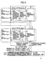
- Each of the cell voltage detection/inter-cell balancing circuits 2 is provided for each of x ⁇ y pieces of the module batteries 10, and is connected to the positive electrode and negative electrode of each of the x pieces of cell batteries 1. Then, the cell voltage detection/inter-cell balancing circuit 2 detects the cell voltage generated in each of the cell batteries 1, and sends the detected cell voltage as the cell voltage signal to the battery management unit 4. Moreover, the cell voltage detection/inter-cell balancing circuit 2 performs the inter-cell balance control to balance the energies among the cell batteries 1 based on an inter-cell balance control signal sent from the battery management unit 4 in response to the cell voltage signal
- Each of the inter-module balancing circuits 3 performs the inter-module balance control to balance the energies among the y ⁇ w pieces of module batteries 10 based on inter-module balance control signal sent from the battery management unit 4.
- the battery management unit 4 manages states of the x ⁇ y pieces of module batteries 10 in a centralized manner, and performs the inter-cell balance control and the inter-module balance control.
- the battery management unit 4 includes an inter-cell balance control circuit 41a, and an inter-module balance control circuit 41b.
- the inter-cell balance control circuit 41a creates inter-cell balance control signals based on the cell voltage signals sent from the cell voltage detection/inter-cell balancing circuits 2 of the y ⁇ w pieces of module batteries 10. Then, the inter-cell balance control signals are sent to the cell voltage detection/inter-cell balancing circuits 2 in the respective module batteries 10 in order to balance the energies among the cell batteries 1 in each of the module batteries 10.
- the inter-module balance control circuit 41b creates inter-module balance control signals based on the cell voltage signals sent from the cell voltage detection/inter-cell balancing circuits 2 of the y ⁇ w pieces of module batteries 10. Then, the inter-module balance control signals are sent to the inter-module balancing circuits 3 in the y ⁇ w pieces of module batteries 10 in order to balance the energies among the y ⁇ w pieces of module batteries 10.
- the battery management unit 4 controls the energy balance among the cell batteries 1 and the energy balance among the module batteries 10. In such a way, the whole of the battery system is managed and controlled in the centralized manner. Therefore, in addition to the effect obtained by the battery system according to Embodiment 1 mentioned above, the control of the energy balance in the whole of the battery system is performed efficiently.
- Each of the module management units 5 is composed of, for example, a circuit including a CPU disposed on a board, an IC having a communication function and a control function, or the like.
- the module management unit 5 controls the whole of the module battery 10 in the centralized manner. Specifically, the module management unit 5 sends the cell voltage signals, which are sent from the cell voltage detection/inter-cell balancing circuit 2, to the battery management unit 4, and sends the inter-cell balance control signal, which is sent from the battery management unit 4, to the cell voltage detection/inter-cell balancing circuit 2, thereby balances the energies among the cell batteries 1. Moreover, the module management unit 5 sends the inter-module balance control signal, which is sent from the battery management unit 4, to the inter-module balancing circuit 3, thereby balances the energies among the module batteries 10.
- the module management unit 5 provided in each of the x ⁇ y pieces of module batteries 10 controls the module battery 10 in the centralized manner. Therefore, in addition to the effect obtained by the battery system according to Embodiment 2, the battery system according to Embodiment 3 of the present invention can perform a more efficient control.
- a battery system according to Embodiment 4 of the present invention which is shown in FIG. 6 , is one that specifically defines main portions of the cell voltage detection/inter-cell balancing circuits 2 and inter-module balancing circuits 3 of the battery system according to either of Embodiment 2 or Embodiment 3.
- the cell voltage detection/inter-cell balancing circuit 2 includes: a cell voltage detection/inter-cell balancing circuit control unit 2a; inter-cell discharge resistors R1, in each of which one end is connected to a voltage detection line drawn out from between ends of the adjacent cell batteries 1 of which number of pieces is x, and the other end is connected to the cell voltage detection/inter-cell balancing circuit control unit 2a; and inter-cell discharge switches SW1, each of which is provided between the other ends of the adjacent inter-cell discharge resistors R1.
- Each of the inter-cell discharge resistors R1 has a function to prevent an increase of a short-circuit current in the case where the voltage detection line is short-circuited.
- Each of the inter-cell discharge switches SW1 opens/closes in response to an inter-cell balancing discharge signal sent from the cell voltage detection/inter-cell balancing circuit control unit 2a.
- the cell voltage detection/inter-cell balancing circuit control unit 2a creates the inter-cell balancing discharge signal, which instructs the discharge of the cell battery 1, in response to the inter-cell balance control signal from the battery management unit 4 (in the case of the battery system according to Embodiment 2) or from the module management unit 5 (in the case of the battery system according to Embodiment 3), and sends the created inter-cell balancing discharge signal to each of the inter-cell discharge switches SW1.
- the cell voltage detection/inter-cell balancing circuit control unit 2a sends the inter-cell balancing discharge signal to the corresponding cell battery 1 outputting a high voltage among the x pieces of cell batteries 1.
- the inter-cell discharge switch SW1 that has received the sent inter-cell balancing discharge signal is closed.
- a current flows through such a route starting from the corresponding cell battery 1, passing through the inter-cell discharge resistor R1, the inter-cell discharge switch SW1 and another inter-cell discharge resistor R1, and returning to the corresponding cell battery 1, and the corresponding cell battery 1 is thereby discharged.
- the cell battery 1 having high energy is discharged so that the energies among the x pieces of cell batteries 1 can be balanced.
- the inter-module balancing circuit 3 includes: a series circuit composed of an inter-module discharge switch SW2 and an inter-module discharge resistor R2, which are provided between the positive electrode of the highest-potential cell battery 1 and the negative electrode of the lowest-potential cell battery 1 among the x pieces of cell batteries; and an inter-module balancing circuit control unit 3a.
- the inter-module discharge switch SW2 opens/clases in response to an inter-module balancing discharge signal from the inter-module balancing circuit control unit 3a.
- the inter-module balancing circuit control unit 3a creates the inter-module balancing discharge signal, which instructs the discharge of the x pieces of cell batteries 1, in response to the inter-module balance control signal from the battery management unit 4 (in the case of the battery system according to Embodiment 2) or from the module management unit 5 (in the case of the battery system according to Embodiment 3), and sends the created inter-module balancing discharge signal to the inter-module discharge switch SW2.
- the inter-module discharge switch SW2 is closed in the case of having received the inter-module balancing discharge signal sent from the inter-module balancing circuit control unit 3a.
- a current flows through such a route starting from the x pieces of cell batteries 1, passing through the inter-module discharge switch SW2 and the inter-module discharge resistor R2, and returning to the x pieces of cell batteries 1, and the x pieces of cell batteries are thereby discharged as a whole.
- the module battery 10 having high energy is discharged so that the energies among the y ⁇ w pieces of module batteries 10 can be balanced.
- a battery system according to Embodiment 5 of the present invention which is shown in FIG. 7 , is one that specifically defines the main portions of the cell voltage detection/inter-cell balancing circuits 2 and inter-module balancing circuits 3 of the battery system according to either of Embodiment 2 or Embodiment 3.
- the cell voltage detection/inter-cell balancing circuit 2 includes: the cell voltage detection/inter-cell balancing circuit control unit 2a; and series circuits, each of which is provided between the adjacent voltage detection lines drawn out from both ends of the x pieces of cell batteries 1, and is composed of the inter-cell discharge switch SW1 that opens/closes in response to the inter-cell balancing discharge signal from the cell voltage detection/inter-cell balancing circuit control unit 2a, and of the inter-cell discharge resistor R1.
- Each of the inter-cell discharge resistors R1 has the function to prevent the increase of the short-circuit current in the case where the voltage detection line is short-circuited.
- Each of the inter-cell discharge switches SW1 opens/closes in response to the inter-cell balancing discharge signal sent from the cell voltage detection/inter-cell balancing circuit control unit 2a.
- the cell voltage detection/inter-cell balancing circuit control unit 2a creates the inter-cell balancing discharge signal, which instructs the discharge of the cell battery 1, in response to the inter-cell balance control signal from the battery management unit 4 (in the case of the battery system according to Embodiment 2) or from the module management unit 5 (in the case of the battery system according to Embodiment 3), and sends the created inter-cell balancing discharge signal to the inter-cell discharge switch SW1.
- the cell voltage detection/inter-cell balancing circuit control unit 2a sends the inter-cell balancing discharge signal to the corresponding cell battery 1 outputting a high voltage among the x pieces of cell batteries 1.
- the inter-cell discharge switch SW1 that has received the inter-cell balancing discharge signal sent from the cell voltage detection/inter-cell balancing circuit control unit 2a is closed.
- a current flows through such a route starting from the corresponding cell battery 1, passing through the inter-cell discharge switch SW1 and the inter-cell discharge resistor R1, and returning to the corresponding cell battery 1, and the corresponding cell battery 1 is thereby discharged.
- the cell battery 1 having high energy is discharged so that the energies among the x pieces of cell batteries 1 can be balanced.
- the inter-module balancing circuit 3 includes: a series circuit that is provided between the positive electrode of the cell battery 1 held at the highest potential and the negative electrode of the cell battery 1 held at the lowest potential among the x pieces of cell batteries, and is composed of the inter-module discharge switch SW2 and the inter-module discharge resistor R2; and the inter-module balancing circuit control unit 3a.
- the inter-module discharge switch SW2 opens/closes in response to the inter-module balancing discharge signal from the inter-module balancing circuit control unit 3a.
- the inter-module balancing circuit control unit 3a creates the inter-module balancing discharge signal, which instructs the discharge of the x pieces of cell batteries 1, in response to the inter-module balance control signal from the battery management unit 4 (in the case of the battery system according to Embodiment 2) or from the module management unit 5 (in the case of the battery system according to Embodiment 3), and sends the created inter-module balancing discharge signal to the inter-module discharge switch SW2.
- the inter-module discharge switch SW2 is closed in the case of having received the inter-module balancing discharge signal sent from the inter-module balancing circuit control unit 3a.
- a current flows through such a route starting from the x pieces of cell batteries 1, passing through the inter-module discharge switch SW2 and the inter-module discharge resistor R2, and returning to the x pieces of cell batteries 1, and the x pieces of cell batteries are thereby discharged as a whole.
- the module battery 10 having high energy is discharged so that the energies among the y ⁇ w pieces of module batteries 10 can be balanced.
- a battery system according to Embodiment 6 of the present invention which is shown in FIG. 8 , is the battery system according to Embodiment 3 mentioned above, in which the module management unit 5 included in each of the module batteries 10 sends a maxim cell voltage V_CellMax and a minimum cell voltage V_CellMin as the cell voltage signals to the battery management unit 4.
- the battery management unit 4 transmits the inter-cell balance control signal to the module battery 10 concerned.
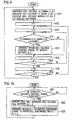
- the inter-cell balance control circuit 41a receives the cell voltage signals from all of the module batteries 10 (Step S11). Specifically, the inter-cell balance control circuit 41a receives the cell voltage signals including the maximum cell voltages V_CellMax (i, j) and the minimum cell voltages V_CellMin (i, j) from the y ⁇ w pieces of module batteries 10.
- the variable i is equal to 1, 2..., and y
- the variable j is equal to 1, 2..., and w.
- variable j is initialized to "1" (Step S12).
- variable i is initialized to "1" (Step S13).
- Step S14 When it is determined in Step S14 that the absolute value of the difference between the maximum cell voltage V_CellMax (i, j) and the minimum cell voltage V_CellMin (i, j) is larger than the threshold value ⁇ VCellB, the inter-cell balance control signal is transmitted to the module battery (i, j) (Step S15).
- Step S14 When it is determined in Step S14 that the absolute value of the difference between the maximum cell voltage V_CellMax (i, j) and the minimum cell voltage V_CellMin (i, j) is not larger than the predetermined threshold value ⁇ VCellB, such processing of Step S15 is skipped.
- Step S16 the variable i is incremented (+1) (Step S16). Subsequently, it is investigated whether or not the variable i has become larger than y, that is, whether or not the processing for the y pieces of module batteries 10 connected in series is ended (Step S17) . When it is determined that the variable i has not become larger than y in Step S17, the operations return to Step S14, and the above-described processing is repeated.
- Step S17 when it is determined that the variable i has become larger than y in Step S17, the variable j is subsequently incremented (+1) (Step S18). Subsequently, it is investigated whether or not the variable j has become larger than w, that is, whether or not the processing for the w pieces of module batteries 10 connected in parallel is ended (Step S19). When it is determined that the variable j has not become larger than w in Step S19, the operations return to Step S13, and the above-described processing is repeated. Meanwhile, when it is determined that the variable j has become larger than w in Step S19, the operations return to Step S11, and the above-described processing is repeated.
- Step S21 it is first investigated whether or not the inter-cell balance control signal has been received thereby.
- Step S21 the cell voltage detection/inter-cell balancing circuit 2 stands by while repeatedly executing Step S21.
- Step S22 When it is determined that the inter-cell balance control signal has been received in such a standby state where Step S21 is repeatedly executed, the maximum voltage cell is specified (Step S22).
- the cell battery specified in Step S22 is represented as a "cell battery (k, i, j)".
- the variable k is equal to 1, 2..., and x.
- the inter-cell balancing discharge signal is transmitted to an inter-cell discharge switch (k, i, j) (Step S23).
- the inter-cell balancing discharge signal is sent to the inter-cell discharge switch SW1 (k, i, j) provided to correspond to the cell battery 1 (k, i, j). In such a way, the cell battery 1 (k, i, j) is discharged.
- the discharge of the cell batteries 1 having the maximum voltages among the cell batteries 1 in each of the module batteries 10 sequentially goes on by the processing of the inter-cell balance control circuit 41a and the cell voltage detection/inter-cell balancing circuit 2, whereby the x pieces of cell batteries 1 are finally made to converge on the minimum cell voltage V_CellMin.
- the energies among the cell batteries 1 in each of the module batteries 10 are balanced. In such a way, the energy in the battery system is balanced.
- the battery system according to Embodiment 6 described above is the battery system according to Embodiment 3 mentioned above, which is configured so that the module management unit 5 included in each of the module batteries 10 can send the maxim cell voltage V_CellMax and the minimum cell voltage V_CellMin as the cell voltage signals to the battery management unit 4.
- the battery system according to Embodiment 6 may be the battery system according to Embodiment 2, which is configured so that the cell voltage detection/inter-cell balancing circuit 2 included in each of the module batteries 10 can send the maxim cell voltage V_CellMax and the minimum cell voltage V_CellMin as the cell voltage signals to the battery management unit 4.
- a configuration of a battery system according to Embodiment 7 of the present invention is the same as the configuration of the battery system according to Embodiment 6 mentioned above; however, the battery system according to Embodiment 7 is different from the battery system according to Embodiment 6 only in operations of each of the cell voltage detection/inter-cell balancing circuits 2. A description will be mainly made below of portions different from those of the battery system according to Embodiment 6.
- FIG. 11 is a flowchart showing the operations of each of the cell voltage detection/inter-cell balancing circuits 2 of the battery system according to Embodiment 7 of the present invention.
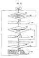
- Step S31 the cell voltage detection/inter-cell balancing circuit 2 investigates whether or not to have received the inter-cell balance control signal.
- Step S31 the cell voltage detection/inter-cell balancing circuit 2 stands by while repeatedly executing Step S31.
- Step S32 When it is determined that the inter-cell balance control signal has been received in a standby state where Step S31 is repeatedly executed, the variable k is initialized to "1" (Step S32).
- the variable k is equal to 1, 2..., and x.
- Step S34 When it is determined in Step S33 that the absolute value of the difference between the voltage V_Cell (k, i, j) of the cell battery 1 and the minimum cell voltage V_CellMin (i, j) thereof is larger than the predetermined threshold value ⁇ VCellB, data (k, i, j) for specifying the cell battery 1 concerned is stored (Step S34). Meanwhile, when it is determined in Step S33 that the absolute value of the difference between the voltage V_Cell (k, i, j) of the cell battery 1 and the minimum cell voltage V_CellMin (i, j) thereof is not larger than the predetermined threshold value ⁇ VCellB, such processing of Step S34 is skipped.
- Step S35 the variable k is incremented (+1) (Step S35). Subsequently, it is investigated whether or not the variable k has become larger than x (Step S36). When it is determined that the variable k has not become larger than x in Step S36, the operations return to Step S33, and the above-described processing is repeated.
- Step S37 when it is determined that the variable k has become larger than x in Step S36, it is investigated whether or not the remainder of a global function (h/2) is "1" (Step S37).
- the inter-cell balancing discharge signal is sent to the inter-cell discharge switches SW1 for discharging the cell batteries 1 in which k is odd in the data (k, i, j) stored in Step S34 (Step S38). Thereafter, the operations return to Step S31, and the above-described processing is repeated.
- Step S37 When it is determined that the remainder of the global function (h/2) is not "1" in Step S37, the inter-cell balancing discharge signal is sent to the inter-cell discharge switches SW1 for discharging the cell batteries 1 in which k is even in the data (k, i, j) stored in Step S34 (Step S39). Thereafter, the operations return to Step S31, and the above-described processing is repeated.
- all of the x pieces of cell batteries 1 are finally made to converge on the minimum cell voltage V_CellMin (i, j). Therefore, a balancing discharge time is shortened without reducing values of the inter-cell discharge resistors R1, that is, without increasing a discharge current.
- the cell batteries 1 with even ordinal numbers and the cell batteries 1 with odd ordinal numbers are discharged alternately, whereby heat generation owing to the discharge can be suppressed without increasing the discharge current.
- a configuration of a battery system according to Embodiment 8 of the present invention is the same as the configuration of the battery system according to Embodiment 7 mentioned above; however, the battery system according to Embodiment 8 is different from the battery system according to Embodiment 7 only in operations of each of the cell voltage detection/inter-cell balancing circuits 2. A description will be mainly made below of portions different from those of the battery system according to Embodiment 7.
- FIG. 12 is a flowchart showing the operations of each of the cell voltage detection/inter-cell balancing circuits 2 of the battery system according to Embodiment 8 of the present invention.
- the same reference numerals as those used in the flowchart of FIG. 11 are assigned to steps of executing the same processing as the processing (refer to the flowchart of FIG. 11 ) executed in the cell voltage detection/inter-cell balancing circuit 2 of the battery system according to embodiment 7, and a description thereof will be omitted.
- Step S31 to S36 the processing from Step S31 to S36 is executed as in Embodiment 7. Then, when it is determined that the variable k has not become larger than x in Step S36, the operations return to Step S33, and the above-mentioned processing is repeated. Meanwhile, when it is determined that the variable k has become larger than x in Step S36, the inter-cell balancing discharge signal is sent to the inter-cell discharge switches SW1 for discharging the cell batteries 1 corresponding to the data (k, i, j) stored in Step S34 mentioned above (Step S41). Thereafter, the operations return to Step S31, and the above-described processing is repeated.
- the balancing discharge time can be shortened without reducing the values of the inter-cell discharge resistors R1.
- a battery system according to Embodiment 9 of the present invention is the battery system according to any one of Embodiment 2 to Embodiment 8, which does not perform the inter-cell balancing discharge at the time of detecting the cell voltage, and performs the inter-cell balancing discharge at the time of not detecting the cell voltage.
- FIG. 13 is a timing chart for explaining operations of the battery system according to Embodiment 9.
- the cell voltage detection/inter-cell balancing circuit 2 of each of the y ⁇ w pieces of module batteries 10 discharges the cell batteries 1 in response to the inter-cell balance control signal sent from the inter-cell balance control circuit 41a or to the inter-cell balance control signal sent from the inter-cell balance control circuit 41a through the module management unit 5 during a period (inter-cell balancing discharge period) excluding a period (cell voltage detection period) of detecting the cell voltage generated in each of the x pieces of cell batteries 1.
- the inter-cell balancing discharge is not performed at the time of detecting the cell voltage, and the inter-cell balancing discharge is performed at the time of not detecting the cell voltage. Therefore, a voltage drop does not occur at the time of detecting the cell voltage.
- the discharge for balancing the cells can be performed without lowering voltage detection accuracy.
- a battery system according to Embodiment 10 of the present invention is the battery system according to Embodiment 9, in which a predetermined margin period is provided between the period of detecting the cell voltage and the period of performing the inter-cell balancing discharge.
- FIG. 14 is a timing chart for explaining operations of the battery system according to Embodiment 10.
- the cell voltage detection/inter-cell balancing circuit 2 of each of the y ⁇ w pieces of module batteries 10 discharges the cell batteries 1 in response to the inter-cell balance control signal sent from the inter-cell balance control circuit 41a or to the inter-cell balance control signal sent from the inter-cell balance control circuit 41a through the module management unit 5 during a period (inter-cell balancing discharge period) excluding the period (cell voltage detection period) of detecting the cell voltage generated in each of the x pieces of cell batteries 1 and the predetermined margin periods before and after the cell voltage detection period.
- the inter-cell balancing discharge is not performed at the time of detecting the cell voltage. Meanwhile, at the time of not detecting the cell voltage, the inter-cell balancing discharge is executed, and in addition, the predetermined margin period is provided between the cell voltage detection period and the inter-cell balancing discharge period. Therefore, the voltage drop that occurs at the time of detecting the cell voltage can be avoided with margin. As a result, in the battery system according to Embodiment 10 of the present invention, the discharge for balancing the cells can be performed without lowering the voltage detection accuracy.
- a configuration of a battery system according to Embodiment 11 of the present invention is the same as the configuration of the battery system according to Embodiment 6, which is shown in FIG. 8 .
- the inter-module balance control circuit 41b receives the cell voltage signals from all of the module batteries 10 (Step S51). Specifically, the inter-module balance control circuit 41b receives the cell voltage signals including the maximum cell voltages V_CellMax (i, j) and the minimum cell voltages V_CellMin (i, j), which are transmitted from the y ⁇ w pieces of module batteries 10.
- a minimum value V_PakMin of the minimum cell voltages of all of the module batteries 10 is selected (Step S52). Specifically, the minimum value V_PakMin is selected from among the minimum cell voltages V_CellMin (i, j) included in the cell voltage signals received in Step S51.
- Step S53 the variable j is initialized to "1"
- Step S54 the variable i is initialized to "1"
- Step S55 it is investigated whether or not an absolute value of a difference between the maximum cell voltage V_CellMax (i, j) acquired in Step S51 and the minimum value V_PakMin selected in Step S52 is larger than a threshold value ⁇ VModuleB
- Step S55 When it is determined in Step S55 that the absolute value of the difference between the maximum cell voltage V_CellMax (i, j) and the minimum value V_PakMin is larger than the threshold value ⁇ VModuleB, the inter-module balance control signal is transmitted to the module battery (i, j) (Step S56).
- Step S55 When it is determined in Step S55 that the absolute value of the difference between the maximum cell voltage V_CellMax (i, j) and the minimum value V_PakMin is not larger than the threshold value ⁇ VModuleB, such processing of Step S56 is skipped.
- Step S57 the variable i is incremented (+1) (Step S57). Subsequently, it is investigated whether or not the variable i has become larger than y, that is, whether or not the processing for the y pieces of module batteries 10 connected in series is ended (Step S58). When it is determined that the variable i has not become larger than y in Step S58, the operations return to Step S55, and the above-described processing is repeated.
- Step S58 when it is determined that the variable i has become larger than y in Step S58, the variable j is subsequently incremented (+1) (Step S59). Subsequently, it is investigated whether or not the variable j has become larger than w, that is, whether or not the processing for the w pieces of module batteries 10 connected in parallel is ended (Step S60). When it is determined that the variable j has not become larger than w in Step S60, the operations return to Step S54, and the above-described processing is repeated. Meanwhile, when it is determined that the variable j has become larger than w in Step S60, the operations return to Step S51, and the above-described processing is repeated.
- Step S61 It is first investigated whether or not the inter-module balancing circuit 3 has received the inter-module balance control signal (Step S61). When it is determined that the inter-module balance control signal has not been received in Step S61, the inter-module balancing circuit 3 stands by while repeatedly executing Step S61.
- Step S62 the inter-module balancing discharge signal is transmitted (Step S62). Specifically, the inter-module balancing discharge signal is sent to the inter-module discharge switch SW2. In such a way, the module battery 10 is discharged as a whole.
- the discharge of the module battery 10 and the discharge of the cell battery 1 are performed in combination.
- the discharge time for balancing the energy therein can be shortened.
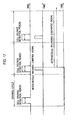
- a battery system according to Embodiment 12 of the present invention is the battery system according to any one of Embodiment 2 to Embodiment 8, which performs the inter-module balancing discharge when required no matter whether or not the cell voltage is being detected.
- FIG. 17 is a timing chart for explaining operations of the battery system according to Embodiment 12.
- the inter-module balancing circuit 3 sends the inter-module balance control signal, which is sent from the inter-module balance control circuit 41b, to the inter-module discharge switch SW2 independently of the detection period of the cell voltage generated in each of the x pieces of cell batteries 1 in the cell voltage detection/inter-cell balancing circuit 2 of each of the y ⁇ w pieces of module batteries 10. Then, a period after the inter-module balance control signal is received is defined as an inter-module balancing discharge period, and the module battery 10 concerned is discharged during this inter-module balancing discharge period.
- the discharge of the module battery 10, which does not affect the detection of the cell voltage is always performed after the inter-module balance control signal from the inter-module balance control signal 41b is received.
- the battery system according to Embodiment 12 of the present invention such a balancing discharge time can be shortened.
Landscapes
- Engineering & Computer Science (AREA)
- Manufacturing & Machinery (AREA)
- Chemical & Material Sciences (AREA)
- Chemical Kinetics & Catalysis (AREA)
- Electrochemistry (AREA)
- General Chemical & Material Sciences (AREA)
- Microelectronics & Electronic Packaging (AREA)
- Secondary Cells (AREA)
- Charge And Discharge Circuits For Batteries Or The Like (AREA)
Applications Claiming Priority (1)
| Application Number | Priority Date | Filing Date | Title |
|---|---|---|---|
| JP2008190916A JP2010029050A (ja) | 2008-07-24 | 2008-07-24 | 電池システム |
Publications (2)
| Publication Number | Publication Date |
|---|---|
| EP2148384A1 true EP2148384A1 (fr) | 2010-01-27 |
| EP2148384B1 EP2148384B1 (fr) | 2011-08-31 |
Family
ID=41312991
Family Applications (1)
| Application Number | Title | Priority Date | Filing Date |
|---|---|---|---|
| EP09009624A Not-in-force EP2148384B1 (fr) | 2008-07-24 | 2009-07-24 | Système de batterie utilisant une batterie secondaire |
Country Status (4)
| Country | Link |
|---|---|
| US (1) | US20100019724A1 (fr) |
| EP (1) | EP2148384B1 (fr) |
| JP (1) | JP2010029050A (fr) |
| AT (1) | ATE522947T1 (fr) |
Cited By (13)
| Publication number | Priority date | Publication date | Assignee | Title |
|---|---|---|---|---|
| EP2244321A1 (fr) * | 2009-04-24 | 2010-10-27 | Sanyo Electric Co., Ltd. | Module de batterie, système de batterie et véhicule électrique |
| WO2012023477A1 (fr) * | 2010-08-17 | 2012-02-23 | Jx日鉱日石エネルギー株式会社 | Appareil de stockage d'énergie |
| WO2012099823A1 (fr) * | 2011-01-20 | 2012-07-26 | Valence Technology, Inc. | Systèmes d'accumulateurs et procédé de fonctionnement de systèmes d'accumulateurs |
| CN102655243A (zh) * | 2011-03-01 | 2012-09-05 | 株式会社日立制作所 | 电池系统 |
| WO2013041386A1 (fr) * | 2011-09-19 | 2013-03-28 | Robert Bosch Gmbh | Système de gestion de batterie, batterie, véhicule automobile avec système de gestion de batterie et procédé de surveillance d'une batterie |
| CN103026544A (zh) * | 2010-06-17 | 2013-04-03 | Sk新技术株式会社 | 高电压电池感测线处的借助于保险丝的安全部件 |
| CN103367819A (zh) * | 2012-03-29 | 2013-10-23 | 株式会社日立制作所 | 电池系统 |
| US8587318B2 (en) | 2010-07-27 | 2013-11-19 | GM Global Technology Operations LLC | Sensor arrangement for an energy storage device and a method of using the same |
| US8922167B2 (en) | 2011-01-20 | 2014-12-30 | Valence Technology, Inc. | Rechargeable battery systems and rechargeable battery system operational methods |
| US8957624B2 (en) | 2011-01-20 | 2015-02-17 | Valence Technology, Inc. | Rechargeable battery systems and rechargeable battery system operational methods |
| WO2017109500A1 (fr) * | 2015-12-22 | 2017-06-29 | Poweroasis Ltd | Commande de batterie multi-modules |
| EP3043440B1 (fr) * | 2015-01-07 | 2020-06-03 | Toyota Jidosha Kabushiki Kaisha | Dispositif de surveillance de batterie |
| EP3982507A4 (fr) * | 2019-10-22 | 2022-11-02 | LG Energy Solution, Ltd. | Dispositif et procédé d'équilibrage de blocs-batteries connectés en parallèle les uns aux autres |
Families Citing this family (53)
| Publication number | Priority date | Publication date | Assignee | Title |
|---|---|---|---|---|
| JP2011041452A (ja) * | 2009-07-17 | 2011-02-24 | Toshiba Corp | 組電池装置及び車両 |
| KR101256952B1 (ko) | 2010-03-05 | 2013-04-25 | 주식회사 엘지화학 | 셀 밸런싱부의 고장 진단 장치 및 방법 |
| KR101137376B1 (ko) * | 2010-04-12 | 2012-04-20 | 삼성에스디아이 주식회사 | 배터리 팩 |
| DE102010027857A1 (de) * | 2010-04-16 | 2011-10-20 | Sb Limotive Company Ltd. | Koppeleinheit und Batteriemodul mit integriertem Pulswechselrichter und erhöhter Zuverlässigkeit |
| CN102299529B (zh) * | 2010-06-25 | 2014-04-02 | 凹凸电子(武汉)有限公司 | 电池组管理系统、电动车及管理电池组的方法 |
| US8446126B2 (en) * | 2010-08-04 | 2013-05-21 | Cooler Master Co., Ltd. | Power bank apparatus with speaker |
| US9851412B2 (en) * | 2010-11-09 | 2017-12-26 | International Business Machines Corporation | Analyzing and controlling performance in a composite battery module |
| JP5634234B2 (ja) * | 2010-11-26 | 2014-12-03 | 株式会社ケーヒン | セルバランス制御装置 |
| US9166437B2 (en) * | 2011-01-26 | 2015-10-20 | Google Inc. | Battery pack |
| JP5537468B2 (ja) * | 2011-03-01 | 2014-07-02 | 株式会社日立製作所 | 蓄電池制御システムおよび蓄電池制御方法 |
| JP5709601B2 (ja) * | 2011-03-25 | 2015-04-30 | 三菱重工業株式会社 | 蓄電装置および蓄電装置の電圧均等化方法 |
| US9641004B2 (en) | 2011-04-20 | 2017-05-02 | A123 Systems, LLC | System and method for balancing charge between battery cells |
| US20120274283A1 (en) * | 2011-04-28 | 2012-11-01 | Van Lammeren Johannes | Battery cell-balancing method and apparatus |
| JP5556745B2 (ja) * | 2011-06-13 | 2014-07-23 | 株式会社デンソー | 組電池電圧制御システム |
| CN102916458B (zh) | 2011-08-05 | 2015-06-17 | 凹凸电子(武汉)有限公司 | 电池均衡系统、电路及其方法 |
| KR101326802B1 (ko) * | 2011-08-24 | 2013-11-11 | 현대오트론 주식회사 | 차량 배터리의 전압 밸런싱 회로 |
| KR101262265B1 (ko) | 2011-11-11 | 2013-05-08 | (주)인텍에프에이 | 전기에너지 저장장치 충전 시스템 |
| EP2789071B1 (fr) * | 2011-12-08 | 2016-03-23 | Volvo Lastvagnar AB | Dispositif d'équilibrage de systèmes de stockage d'énergie |
| US20130257381A1 (en) * | 2012-03-29 | 2013-10-03 | Steven Diamond | Peak-equalized battery charge balancing |
| US9728820B2 (en) * | 2012-03-29 | 2017-08-08 | Atieva, Inc. | Margin-based battery charge balancing |
| DE112012005647T5 (de) * | 2012-04-30 | 2014-10-30 | Hewlett-Packard Development Company, L.P. | Laden eines Energiespeichers von einer justierbaren Stromquelle |
| KR101472886B1 (ko) * | 2012-05-21 | 2014-12-15 | 주식회사 엘지화학 | 전지팩의 전압 밸런싱 장치 및 방법 |
| JP2013247690A (ja) * | 2012-05-23 | 2013-12-09 | Toyota Industries Corp | 電圧均等化装置 |
| KR101942969B1 (ko) | 2012-08-30 | 2019-01-28 | 삼성전자주식회사 | 밸런싱 장치, 밸런싱 방법 및 배터리 모듈 |
| JP5856934B2 (ja) * | 2012-09-14 | 2016-02-10 | 株式会社日立製作所 | 蓄電池システムの制御方法 |
| KR101942970B1 (ko) * | 2012-09-21 | 2019-01-28 | 삼성전자주식회사 | 밸런싱 방법 및 배터리 시스템 |
| JP5583194B2 (ja) * | 2012-11-21 | 2014-09-03 | 三菱重工業株式会社 | 電池システム、電池管理装置及び電池管理方法 |
| US9472959B2 (en) * | 2012-11-30 | 2016-10-18 | GM Global Technology Operations LLC | Systems and methods for balancing a vehicle battery system |
| US8901888B1 (en) | 2013-07-16 | 2014-12-02 | Christopher V. Beckman | Batteries for optimizing output and charge balance with adjustable, exportable and addressable characteristics |
| KR101592200B1 (ko) * | 2013-08-28 | 2016-02-05 | 주식회사 엘지화학 | 랙을 포함하는 전지팩의 랙 전압 밸런싱 방법 |
| JP6127856B2 (ja) * | 2013-09-17 | 2017-05-17 | 株式会社デンソー | 電池監視装置 |
| US20150280461A1 (en) * | 2014-03-26 | 2015-10-01 | International Business Machines Corporation | Adjusting charge voltage on cells in multi-cell battery |
| US20150276886A1 (en) * | 2014-03-26 | 2015-10-01 | International Business Machines Corporation | Adjusting charge voltage on cells in multi-cell battery |
| CN106374475A (zh) * | 2015-07-23 | 2017-02-01 | 利思电气(上海)有限公司 | 一种链式高压有源滤波器的虚拟链节控制装置 |
| WO2017073018A1 (fr) * | 2015-10-30 | 2017-05-04 | 三洋電機株式会社 | Dispositif et système de stockage d'électricité |
| WO2017132529A1 (fr) * | 2016-01-27 | 2017-08-03 | The University Of Toledo | Égaliseur à deux niveaux pour gestion de charge d'élément de batterie |
| KR20180044483A (ko) | 2016-10-21 | 2018-05-03 | 주식회사 엘지화학 | 셀 밸런싱 시스템 및 제어방법 |
| KR20180044484A (ko) | 2016-10-21 | 2018-05-03 | 주식회사 엘지화학 | 충전전압 공급장치 및 공급방법 |
| US10516189B2 (en) * | 2016-11-15 | 2019-12-24 | Ford Global Technologies, Llc | High voltage bus contactor fault detection |
| JP2018117438A (ja) * | 2017-01-17 | 2018-07-26 | 太陽誘電株式会社 | リチウムイオンキャパシタを備えた電源モジュール |
| US10439404B2 (en) | 2017-04-13 | 2019-10-08 | Microsoft Technology Licensing, Llc | Hybrid battery pack including bi-directional charge regulator |
| KR102204301B1 (ko) * | 2017-07-20 | 2021-01-15 | 주식회사 엘지화학 | 무선 배터리 관리 시스템 및 이를 포함하는 배터리팩 |
| WO2019022071A1 (fr) * | 2017-07-24 | 2019-01-31 | 工機ホールディングス株式会社 | Bloc-batterie et dispositif électronique utilisant un bloc-batterie |
| KR102202613B1 (ko) | 2017-09-27 | 2021-01-12 | 주식회사 엘지화학 | 배터리 모듈 균등화 장치, 이를 포함하는 배터리 팩 및 자동차 |
| US11239670B2 (en) * | 2018-09-16 | 2022-02-01 | Richard Landry Gray | Cell balancing battery module and electrical apparatus |
| JP7259983B2 (ja) * | 2019-10-28 | 2023-04-18 | 工機ホールディングス株式会社 | 電池パック及び電気機器 |
| CN112838994B (zh) | 2019-11-22 | 2024-03-19 | 中兴通讯股份有限公司 | 链路预均衡补偿方法及装置、存储介质、电子装置 |
| KR102343790B1 (ko) * | 2019-12-31 | 2021-12-27 | 한국기술교육대학교 산학협력단 | 셀프 에너지 밸런싱을 고려한 배터리 관리 시스템 및 이를 이용한 배터리 관리방법 |
| JP2021191011A (ja) * | 2020-05-25 | 2021-12-13 | 株式会社デンソー | 電池監視装置 |
| WO2022269829A1 (fr) * | 2021-06-23 | 2022-12-29 | 株式会社EViP | Circuit d'alimentation de moteur |
| TWI818593B (zh) * | 2022-06-20 | 2023-10-11 | 新盛力科技股份有限公司 | 電池設備的放電平衡方法 |
| JP2024080204A (ja) * | 2022-12-02 | 2024-06-13 | 株式会社日立製作所 | 組電池装置及びエネルギー貯蔵システム |
| US20250074529A1 (en) * | 2023-08-29 | 2025-03-06 | C-Tech United Corporation | Auxiliary assembly for bicycle |
Citations (5)
| Publication number | Priority date | Publication date | Assignee | Title |
|---|---|---|---|---|
| US5631534A (en) * | 1995-08-21 | 1997-05-20 | Delco Electronics Corp. | Bidirectional current pump for battery charge balancing |
| JPH11150877A (ja) | 1997-11-17 | 1999-06-02 | Toshiba Battery Co Ltd | 二次電池の電圧補正回路 |
| JP3331201B2 (ja) | 1999-12-22 | 2002-10-07 | 株式会社日立製作所 | 組電池の電池電圧補正装置 |
| US6511764B1 (en) * | 1997-10-20 | 2003-01-28 | Usar Systems, Inc. | Voltaic pile with charge equalizing system |
| US20060076923A1 (en) * | 2004-08-13 | 2006-04-13 | Eaves Stephen S | Methods and systems for assembling batteries |
Family Cites Families (8)
| Publication number | Priority date | Publication date | Assignee | Title |
|---|---|---|---|---|
| US346103A (en) * | 1886-07-27 | Milling-tool | ||
| US364193A (en) * | 1887-05-31 | Edmund townsend | ||
| JP3823840B2 (ja) * | 2002-02-14 | 2006-09-20 | 日産自動車株式会社 | 組電池の電圧検出装置 |
| JP4116589B2 (ja) * | 2004-05-14 | 2008-07-09 | パナソニックEvエナジー株式会社 | 容量均等化装置 |
| JP4186916B2 (ja) * | 2004-11-18 | 2008-11-26 | 株式会社デンソー | 組電池管理装置 |
| JP4151662B2 (ja) * | 2005-03-08 | 2008-09-17 | 株式会社デンソー | 組電池の充電電圧均等化回路の制御方法及び制御装置 |
| JP5002919B2 (ja) * | 2005-07-07 | 2012-08-15 | 日産自動車株式会社 | 電圧ばらつき制御装置 |
| JP4888041B2 (ja) * | 2006-02-16 | 2012-02-29 | 株式会社デンソー | 組電池の電圧調整装置 |
-
2008
- 2008-07-24 JP JP2008190916A patent/JP2010029050A/ja active Pending
-
2009
- 2009-07-23 US US12/508,173 patent/US20100019724A1/en not_active Abandoned
- 2009-07-24 AT AT09009624T patent/ATE522947T1/de not_active IP Right Cessation
- 2009-07-24 EP EP09009624A patent/EP2148384B1/fr not_active Not-in-force
Patent Citations (5)
| Publication number | Priority date | Publication date | Assignee | Title |
|---|---|---|---|---|
| US5631534A (en) * | 1995-08-21 | 1997-05-20 | Delco Electronics Corp. | Bidirectional current pump for battery charge balancing |
| US6511764B1 (en) * | 1997-10-20 | 2003-01-28 | Usar Systems, Inc. | Voltaic pile with charge equalizing system |
| JPH11150877A (ja) | 1997-11-17 | 1999-06-02 | Toshiba Battery Co Ltd | 二次電池の電圧補正回路 |
| JP3331201B2 (ja) | 1999-12-22 | 2002-10-07 | 株式会社日立製作所 | 組電池の電池電圧補正装置 |
| US20060076923A1 (en) * | 2004-08-13 | 2006-04-13 | Eaves Stephen S | Methods and systems for assembling batteries |
Cited By (28)
| Publication number | Priority date | Publication date | Assignee | Title |
|---|---|---|---|---|
| EP2244321A1 (fr) * | 2009-04-24 | 2010-10-27 | Sanyo Electric Co., Ltd. | Module de batterie, système de batterie et véhicule électrique |
| CN103026544B (zh) * | 2010-06-17 | 2015-05-06 | Sk新技术株式会社 | 高电压电池感测线处的借助于保险丝的安全部件 |
| EP2583346A4 (fr) * | 2010-06-17 | 2013-12-11 | Sk Innovation Co Ltd | Composant de sécurité à fusible sur une ligne de détection de batterie haute tension. |
| CN103026544A (zh) * | 2010-06-17 | 2013-04-03 | Sk新技术株式会社 | 高电压电池感测线处的借助于保险丝的安全部件 |
| US8587318B2 (en) | 2010-07-27 | 2013-11-19 | GM Global Technology Operations LLC | Sensor arrangement for an energy storage device and a method of using the same |
| DE102011108038B4 (de) | 2010-07-27 | 2019-07-18 | GM Global Technology Operations LLC (n. d. Gesetzen des Staates Delaware) | Verfahren zur Verwendung einer Sensoranordnung für eine Energiespeichereinrichtung |
| WO2012023477A1 (fr) * | 2010-08-17 | 2012-02-23 | Jx日鉱日石エネルギー株式会社 | Appareil de stockage d'énergie |
| US9912178B2 (en) | 2011-01-20 | 2018-03-06 | Valence Technology, Inc. | Rechargeable battery systems and rechargeable battery system operational methods |
| WO2012099823A1 (fr) * | 2011-01-20 | 2012-07-26 | Valence Technology, Inc. | Systèmes d'accumulateurs et procédé de fonctionnement de systèmes d'accumulateurs |
| US11616375B2 (en) | 2011-01-20 | 2023-03-28 | Lithion Battery Inc. | Rechargeable battery systems and rechargeable battery system operational methods |
| US8773068B2 (en) | 2011-01-20 | 2014-07-08 | Valence Technology, Inc. | Rechargeable battery systems and rechargeable battery system operational methods |
| US10903661B2 (en) | 2011-01-20 | 2021-01-26 | Lithium Werks Technology Bv | Rechargeable battery systems and rechargeable battery system operational methods |
| US10056764B2 (en) | 2011-01-20 | 2018-08-21 | Lithium Werks B.V. | Rechargeable battery systems and rechargeable battery system operational methods |
| US8922167B2 (en) | 2011-01-20 | 2014-12-30 | Valence Technology, Inc. | Rechargeable battery systems and rechargeable battery system operational methods |
| US8957624B2 (en) | 2011-01-20 | 2015-02-17 | Valence Technology, Inc. | Rechargeable battery systems and rechargeable battery system operational methods |
| CN102655243A (zh) * | 2011-03-01 | 2012-09-05 | 株式会社日立制作所 | 电池系统 |
| US9112247B2 (en) | 2011-03-01 | 2015-08-18 | Hitachi, Ltd. | Battery system |
| CN102655243B (zh) * | 2011-03-01 | 2014-10-22 | 株式会社日立制作所 | 电池系统 |
| EP2495802A3 (fr) * | 2011-03-01 | 2012-11-28 | Hitachi Ltd. | Système de batteries |
| CN103975478B (zh) * | 2011-09-19 | 2016-10-19 | 罗伯特·博世有限公司 | 蓄电池管理系统、具有蓄电池管理系统的蓄电池和机动车以及用于监控蓄电池的方法 |
| US9846198B2 (en) | 2011-09-19 | 2017-12-19 | Robert Bosch Gmbh | Battery management system, battery, motor vehicle having a battery management system, and method for monitoring a battery |
| CN103975478A (zh) * | 2011-09-19 | 2014-08-06 | 罗伯特·博世有限公司 | 蓄电池管理系统、具有蓄电池管理系统的蓄电池和机动车以及用于监控蓄电池的方法 |
| WO2013041386A1 (fr) * | 2011-09-19 | 2013-03-28 | Robert Bosch Gmbh | Système de gestion de batterie, batterie, véhicule automobile avec système de gestion de batterie et procédé de surveillance d'une batterie |
| CN103367819B (zh) * | 2012-03-29 | 2016-01-06 | 株式会社日立制作所 | 电池系统 |
| CN103367819A (zh) * | 2012-03-29 | 2013-10-23 | 株式会社日立制作所 | 电池系统 |
| EP3043440B1 (fr) * | 2015-01-07 | 2020-06-03 | Toyota Jidosha Kabushiki Kaisha | Dispositif de surveillance de batterie |
| WO2017109500A1 (fr) * | 2015-12-22 | 2017-06-29 | Poweroasis Ltd | Commande de batterie multi-modules |
| EP3982507A4 (fr) * | 2019-10-22 | 2022-11-02 | LG Energy Solution, Ltd. | Dispositif et procédé d'équilibrage de blocs-batteries connectés en parallèle les uns aux autres |
Also Published As
| Publication number | Publication date |
|---|---|
| ATE522947T1 (de) | 2011-09-15 |
| US20100019724A1 (en) | 2010-01-28 |
| JP2010029050A (ja) | 2010-02-04 |
| EP2148384B1 (fr) | 2011-08-31 |
Similar Documents
| Publication | Publication Date | Title |
|---|---|---|
| EP2148384B1 (fr) | Système de batterie utilisant une batterie secondaire | |
| EP3809553B1 (fr) | Système de batterie | |
| KR100991084B1 (ko) | 멀티 전지 팩 시스템 및 그 제어방법, 및 이를 이용한 전지팩 | |
| CN101714649B (zh) | 电池部件以及使用了该电池部件的电池系统 | |
| US9564768B2 (en) | Discharge device for electricity storage device | |
| US10408864B2 (en) | Voltage measuring apparatus, voltage measuring method, voltage control apparatus, and voltage control method | |
| JP2011041463A (ja) | リチウムイオン電池の電圧バランス制御システム、及びその制御方法 | |
| JP2013078242A (ja) | 電源装置 | |
| KR102488746B1 (ko) | 배터리 밸런싱 시스템 | |
| JP5324381B2 (ja) | 充電制御装置、および該充電制御装置における充電制御方法 | |
| US8441234B2 (en) | Detecting module for a battery equalizer and method for detecting a battery equalizer | |
| JP3709766B2 (ja) | 組電池の容量調整方法 | |
| WO2022236545A1 (fr) | Système de batterie et procédé de commande | |
| JPWO2014192134A1 (ja) | 蓄電池監視装置 | |
| JP5314626B2 (ja) | 電源システム、放電制御方法および放電制御プログラム | |
| KR101909104B1 (ko) | 배터리팩 밸런싱이 가능한 에너지 저장 장치 | |
| KR101042833B1 (ko) | 셀 밸런싱 회로 및 이를 구비하는 이차전지 | |
| WO2019069971A1 (fr) | Batterie assemblée | |
| JP4767766B2 (ja) | 電池管理システム及び電池管理方法 | |
| KR20180035080A (ko) | 배터리 셀 밸런싱 회로 | |
| JP2008079364A (ja) | 充放電装置 | |
| EP4207548B1 (fr) | Appareil de gestion de batterie et son procédé de fonctionnement | |
| CN110015130A (zh) | 电池均衡系统、车辆、电池均衡方法及存储介质 | |
| KR102918559B1 (ko) | 배터리 관리 장치 및 그것의 동작 방법 | |
| JP2009072038A (ja) | 組電池の電圧検出装置及びその制御方法 |
Legal Events
| Date | Code | Title | Description |
|---|---|---|---|
| PUAI | Public reference made under article 153(3) epc to a published international application that has entered the european phase |
Free format text: ORIGINAL CODE: 0009012 |
|
| 17P | Request for examination filed |
Effective date: 20090724 |
|
| AK | Designated contracting states |
Kind code of ref document: A1 Designated state(s): AT BE BG CH CY CZ DE DK EE ES FI FR GB GR HR HU IE IS IT LI LT LU LV MC MK MT NL NO PL PT RO SE SI SK SM TR |
|
| AX | Request for extension of the european patent |
Extension state: AL BA RS |
|
| GRAP | Despatch of communication of intention to grant a patent |
Free format text: ORIGINAL CODE: EPIDOSNIGR1 |
|
| GRAC | Information related to communication of intention to grant a patent modified |
Free format text: ORIGINAL CODE: EPIDOSCIGR1 |
|
| GRAS | Grant fee paid |
Free format text: ORIGINAL CODE: EPIDOSNIGR3 |
|
| GRAA | (expected) grant |
Free format text: ORIGINAL CODE: 0009210 |
|
| AK | Designated contracting states |
Kind code of ref document: B1 Designated state(s): AT BE BG CH CY CZ DE DK EE ES FI FR GB GR HR HU IE IS IT LI LT LU LV MC MK MT NL NO PL PT RO SE SI SK SM TR |
|
| REG | Reference to a national code |
Ref country code: CH Ref legal event code: EP Ref country code: GB Ref legal event code: FG4D |
|
| REG | Reference to a national code |
Ref country code: IE Ref legal event code: FG4D |
|
| REG | Reference to a national code |
Ref country code: DE Ref legal event code: R096 Ref document number: 602009002326 Country of ref document: DE Effective date: 20111201 |
|
| REG | Reference to a national code |
Ref country code: NL Ref legal event code: VDEP Effective date: 20110831 |
|
| LTIE | Lt: invalidation of european patent or patent extension |
Effective date: 20110831 |
|
| PG25 | Lapsed in a contracting state [announced via postgrant information from national office to epo] |
Ref country code: NO Free format text: LAPSE BECAUSE OF FAILURE TO SUBMIT A TRANSLATION OF THE DESCRIPTION OR TO PAY THE FEE WITHIN THE PRESCRIBED TIME-LIMIT Effective date: 20111130 Ref country code: IS Free format text: LAPSE BECAUSE OF FAILURE TO SUBMIT A TRANSLATION OF THE DESCRIPTION OR TO PAY THE FEE WITHIN THE PRESCRIBED TIME-LIMIT Effective date: 20111231 Ref country code: FI Free format text: LAPSE BECAUSE OF FAILURE TO SUBMIT A TRANSLATION OF THE DESCRIPTION OR TO PAY THE FEE WITHIN THE PRESCRIBED TIME-LIMIT Effective date: 20110831 Ref country code: LT Free format text: LAPSE BECAUSE OF FAILURE TO SUBMIT A TRANSLATION OF THE DESCRIPTION OR TO PAY THE FEE WITHIN THE PRESCRIBED TIME-LIMIT Effective date: 20110831 Ref country code: HR Free format text: LAPSE BECAUSE OF FAILURE TO SUBMIT A TRANSLATION OF THE DESCRIPTION OR TO PAY THE FEE WITHIN THE PRESCRIBED TIME-LIMIT Effective date: 20110831 Ref country code: SE Free format text: LAPSE BECAUSE OF FAILURE TO SUBMIT A TRANSLATION OF THE DESCRIPTION OR TO PAY THE FEE WITHIN THE PRESCRIBED TIME-LIMIT Effective date: 20110831 Ref country code: NL Free format text: LAPSE BECAUSE OF FAILURE TO SUBMIT A TRANSLATION OF THE DESCRIPTION OR TO PAY THE FEE WITHIN THE PRESCRIBED TIME-LIMIT Effective date: 20110831 |
|
| REG | Reference to a national code |
Ref country code: AT Ref legal event code: MK05 Ref document number: 522947 Country of ref document: AT Kind code of ref document: T Effective date: 20110831 |
|
| PG25 | Lapsed in a contracting state [announced via postgrant information from national office to epo] |
Ref country code: LV Free format text: LAPSE BECAUSE OF FAILURE TO SUBMIT A TRANSLATION OF THE DESCRIPTION OR TO PAY THE FEE WITHIN THE PRESCRIBED TIME-LIMIT Effective date: 20110831 Ref country code: AT Free format text: LAPSE BECAUSE OF FAILURE TO SUBMIT A TRANSLATION OF THE DESCRIPTION OR TO PAY THE FEE WITHIN THE PRESCRIBED TIME-LIMIT Effective date: 20110831 Ref country code: SI Free format text: LAPSE BECAUSE OF FAILURE TO SUBMIT A TRANSLATION OF THE DESCRIPTION OR TO PAY THE FEE WITHIN THE PRESCRIBED TIME-LIMIT Effective date: 20110831 Ref country code: CY Free format text: LAPSE BECAUSE OF FAILURE TO SUBMIT A TRANSLATION OF THE DESCRIPTION OR TO PAY THE FEE WITHIN THE PRESCRIBED TIME-LIMIT Effective date: 20110831 Ref country code: GR Free format text: LAPSE BECAUSE OF FAILURE TO SUBMIT A TRANSLATION OF THE DESCRIPTION OR TO PAY THE FEE WITHIN THE PRESCRIBED TIME-LIMIT Effective date: 20111201 |
|
| PG25 | Lapsed in a contracting state [announced via postgrant information from national office to epo] |
Ref country code: BE Free format text: LAPSE BECAUSE OF FAILURE TO SUBMIT A TRANSLATION OF THE DESCRIPTION OR TO PAY THE FEE WITHIN THE PRESCRIBED TIME-LIMIT Effective date: 20110831 |
|
| PG25 | Lapsed in a contracting state [announced via postgrant information from national office to epo] |
Ref country code: SK Free format text: LAPSE BECAUSE OF FAILURE TO SUBMIT A TRANSLATION OF THE DESCRIPTION OR TO PAY THE FEE WITHIN THE PRESCRIBED TIME-LIMIT Effective date: 20110831 Ref country code: CZ Free format text: LAPSE BECAUSE OF FAILURE TO SUBMIT A TRANSLATION OF THE DESCRIPTION OR TO PAY THE FEE WITHIN THE PRESCRIBED TIME-LIMIT Effective date: 20110831 |
|
| PG25 | Lapsed in a contracting state [announced via postgrant information from national office to epo] |
Ref country code: PL Free format text: LAPSE BECAUSE OF FAILURE TO SUBMIT A TRANSLATION OF THE DESCRIPTION OR TO PAY THE FEE WITHIN THE PRESCRIBED TIME-LIMIT Effective date: 20110831 Ref country code: RO Free format text: LAPSE BECAUSE OF FAILURE TO SUBMIT A TRANSLATION OF THE DESCRIPTION OR TO PAY THE FEE WITHIN THE PRESCRIBED TIME-LIMIT Effective date: 20110831 Ref country code: IT Free format text: LAPSE BECAUSE OF FAILURE TO SUBMIT A TRANSLATION OF THE DESCRIPTION OR TO PAY THE FEE WITHIN THE PRESCRIBED TIME-LIMIT Effective date: 20110831 Ref country code: EE Free format text: LAPSE BECAUSE OF FAILURE TO SUBMIT A TRANSLATION OF THE DESCRIPTION OR TO PAY THE FEE WITHIN THE PRESCRIBED TIME-LIMIT Effective date: 20110831 Ref country code: PT Free format text: LAPSE BECAUSE OF FAILURE TO SUBMIT A TRANSLATION OF THE DESCRIPTION OR TO PAY THE FEE WITHIN THE PRESCRIBED TIME-LIMIT Effective date: 20120102 |
|
| PG25 | Lapsed in a contracting state [announced via postgrant information from national office to epo] |
Ref country code: DK Free format text: LAPSE BECAUSE OF FAILURE TO SUBMIT A TRANSLATION OF THE DESCRIPTION OR TO PAY THE FEE WITHIN THE PRESCRIBED TIME-LIMIT Effective date: 20110831 |
|
| PLBE | No opposition filed within time limit |
Free format text: ORIGINAL CODE: 0009261 |
|
| STAA | Information on the status of an ep patent application or granted ep patent |
Free format text: STATUS: NO OPPOSITION FILED WITHIN TIME LIMIT |
|
| 26N | No opposition filed |
Effective date: 20120601 |
|
| REG | Reference to a national code |
Ref country code: DE Ref legal event code: R097 Ref document number: 602009002326 Country of ref document: DE Effective date: 20120601 |
|
| PG25 | Lapsed in a contracting state [announced via postgrant information from national office to epo] |
Ref country code: MK Free format text: LAPSE BECAUSE OF FAILURE TO SUBMIT A TRANSLATION OF THE DESCRIPTION OR TO PAY THE FEE WITHIN THE PRESCRIBED TIME-LIMIT Effective date: 20110831 Ref country code: MC Free format text: LAPSE BECAUSE OF NON-PAYMENT OF DUE FEES Effective date: 20120731 |
|
| PG25 | Lapsed in a contracting state [announced via postgrant information from national office to epo] |
Ref country code: ES Free format text: LAPSE BECAUSE OF FAILURE TO SUBMIT A TRANSLATION OF THE DESCRIPTION OR TO PAY THE FEE WITHIN THE PRESCRIBED TIME-LIMIT Effective date: 20111211 |
|
| REG | Reference to a national code |
Ref country code: IE Ref legal event code: MM4A |
|
| PG25 | Lapsed in a contracting state [announced via postgrant information from national office to epo] |
Ref country code: BG Free format text: LAPSE BECAUSE OF FAILURE TO SUBMIT A TRANSLATION OF THE DESCRIPTION OR TO PAY THE FEE WITHIN THE PRESCRIBED TIME-LIMIT Effective date: 20111130 |
|
| PG25 | Lapsed in a contracting state [announced via postgrant information from national office to epo] |
Ref country code: IE Free format text: LAPSE BECAUSE OF NON-PAYMENT OF DUE FEES Effective date: 20120724 Ref country code: MT Free format text: LAPSE BECAUSE OF FAILURE TO SUBMIT A TRANSLATION OF THE DESCRIPTION OR TO PAY THE FEE WITHIN THE PRESCRIBED TIME-LIMIT Effective date: 20110831 |
|
| REG | Reference to a national code |
Ref country code: CH Ref legal event code: PL |
|
| PG25 | Lapsed in a contracting state [announced via postgrant information from national office to epo] |
Ref country code: TR Free format text: LAPSE BECAUSE OF FAILURE TO SUBMIT A TRANSLATION OF THE DESCRIPTION OR TO PAY THE FEE WITHIN THE PRESCRIBED TIME-LIMIT Effective date: 20110831 Ref country code: CH Free format text: LAPSE BECAUSE OF NON-PAYMENT OF DUE FEES Effective date: 20130731 Ref country code: LI Free format text: LAPSE BECAUSE OF NON-PAYMENT OF DUE FEES Effective date: 20130731 |
|
| PG25 | Lapsed in a contracting state [announced via postgrant information from national office to epo] |
Ref country code: LU Free format text: LAPSE BECAUSE OF NON-PAYMENT OF DUE FEES Effective date: 20120724 Ref country code: SM Free format text: LAPSE BECAUSE OF FAILURE TO SUBMIT A TRANSLATION OF THE DESCRIPTION OR TO PAY THE FEE WITHIN THE PRESCRIBED TIME-LIMIT Effective date: 20110831 |
|
| PG25 | Lapsed in a contracting state [announced via postgrant information from national office to epo] |
Ref country code: HU Free format text: LAPSE BECAUSE OF FAILURE TO SUBMIT A TRANSLATION OF THE DESCRIPTION OR TO PAY THE FEE WITHIN THE PRESCRIBED TIME-LIMIT Effective date: 20090724 |
|
| REG | Reference to a national code |
Ref country code: FR Ref legal event code: PLFP Year of fee payment: 7 |
|
| PGFP | Annual fee paid to national office [announced via postgrant information from national office to epo] |
Ref country code: DE Payment date: 20150722 Year of fee payment: 7 Ref country code: GB Payment date: 20150722 Year of fee payment: 7 |
|
| PGFP | Annual fee paid to national office [announced via postgrant information from national office to epo] |
Ref country code: FR Payment date: 20150629 Year of fee payment: 7 |
|
| REG | Reference to a national code |
Ref country code: DE Ref legal event code: R119 Ref document number: 602009002326 Country of ref document: DE |
|
| GBPC | Gb: european patent ceased through non-payment of renewal fee |
Effective date: 20160724 |
|
| PG25 | Lapsed in a contracting state [announced via postgrant information from national office to epo] |
Ref country code: DE Free format text: LAPSE BECAUSE OF NON-PAYMENT OF DUE FEES Effective date: 20170201 Ref country code: FR Free format text: LAPSE BECAUSE OF NON-PAYMENT OF DUE FEES Effective date: 20160801 |
|
| REG | Reference to a national code |
Ref country code: FR Ref legal event code: ST Effective date: 20170331 |
|
| PG25 | Lapsed in a contracting state [announced via postgrant information from national office to epo] |
Ref country code: GB Free format text: LAPSE BECAUSE OF NON-PAYMENT OF DUE FEES Effective date: 20160724 |