EP2148408A1 - Agencement de cône plieur pour une imprimante à rouleaux - Google Patents
Agencement de cône plieur pour une imprimante à rouleaux Download PDFInfo
- Publication number
- EP2148408A1 EP2148408A1 EP09165911A EP09165911A EP2148408A1 EP 2148408 A1 EP2148408 A1 EP 2148408A1 EP 09165911 A EP09165911 A EP 09165911A EP 09165911 A EP09165911 A EP 09165911A EP 2148408 A1 EP2148408 A1 EP 2148408A1
- Authority
- EP
- European Patent Office
- Prior art keywords
- rotor
- synchronous machine
- rings
- machine according
- inner ring
- Prior art date
- Legal status (The legal status is an assumption and is not a legal conclusion. Google has not performed a legal analysis and makes no representation as to the accuracy of the status listed.)
- Withdrawn
Links
Images
Classifications
-
- H—ELECTRICITY
- H02—GENERATION; CONVERSION OR DISTRIBUTION OF ELECTRIC POWER
- H02K—DYNAMO-ELECTRIC MACHINES
- H02K1/00—Details of the magnetic circuit
- H02K1/06—Details of the magnetic circuit characterised by the shape, form or construction
- H02K1/22—Rotating parts of the magnetic circuit
- H02K1/26—Rotor cores with slots for windings
-
- H—ELECTRICITY
- H02—GENERATION; CONVERSION OR DISTRIBUTION OF ELECTRIC POWER
- H02K—DYNAMO-ELECTRIC MACHINES
- H02K19/00—Synchronous motors or generators
- H02K19/16—Synchronous generators
- H02K19/22—Synchronous generators having windings each turn of which co-operates alternately with poles of opposite polarity, e.g. heteropolar generators
-
- H—ELECTRICITY
- H02—GENERATION; CONVERSION OR DISTRIBUTION OF ELECTRIC POWER
- H02K—DYNAMO-ELECTRIC MACHINES
- H02K1/00—Details of the magnetic circuit
- H02K1/06—Details of the magnetic circuit characterised by the shape, form or construction
- H02K1/22—Rotating parts of the magnetic circuit
- H02K1/28—Means for mounting or fastening rotating magnetic parts on to, or to, the rotor structures
-
- H—ELECTRICITY
- H02—GENERATION; CONVERSION OR DISTRIBUTION OF ELECTRIC POWER
- H02K—DYNAMO-ELECTRIC MACHINES
- H02K1/00—Details of the magnetic circuit
- H02K1/06—Details of the magnetic circuit characterised by the shape, form or construction
- H02K1/22—Rotating parts of the magnetic circuit
- H02K1/32—Rotating parts of the magnetic circuit with channels or ducts for flow of cooling medium
-
- H—ELECTRICITY
- H02—GENERATION; CONVERSION OR DISTRIBUTION OF ELECTRIC POWER
- H02K—DYNAMO-ELECTRIC MACHINES
- H02K3/00—Details of windings
- H02K3/04—Windings characterised by the conductor shape, form or construction, e.g. with bar conductors
- H02K3/12—Windings characterised by the conductor shape, form or construction, e.g. with bar conductors arranged in slots
- H02K3/16—Windings characterised by the conductor shape, form or construction, e.g. with bar conductors arranged in slots for auxiliary purposes, e.g. damping or commutating
-
- Y—GENERAL TAGGING OF NEW TECHNOLOGICAL DEVELOPMENTS; GENERAL TAGGING OF CROSS-SECTIONAL TECHNOLOGIES SPANNING OVER SEVERAL SECTIONS OF THE IPC; TECHNICAL SUBJECTS COVERED BY FORMER USPC CROSS-REFERENCE ART COLLECTIONS [XRACs] AND DIGESTS
- Y10—TECHNICAL SUBJECTS COVERED BY FORMER USPC
- Y10T—TECHNICAL SUBJECTS COVERED BY FORMER US CLASSIFICATION
- Y10T29/00—Metal working
- Y10T29/49—Method of mechanical manufacture
- Y10T29/49002—Electrical device making
- Y10T29/49009—Dynamoelectric machine
- Y10T29/49012—Rotor
Definitions
- the present invention relates to the field of rotary electric machines. It relates to a synchronous machine according to the preamble of claim 1 and a method for producing such a synchronous machine.
- the damper currents occurring in these operating or fault cases counteract the magnetic field change entering from the stator into the rotor.
- the field increase in the rotor interior is greatly reduced.
- the tangential magnetic field strength in the air gap increases sharply.
- the synchronous machine 10 eg, a turbogenerator
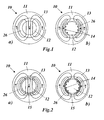
- the synchronous machine 10 comprises a central rotor 12 which is concentrically enclosed by a stator 11. Between the two there is an annular air gap 26.
- the stator magnetic field 13 In steady-state operation (left part of the figure 1 (a)) with symmetrical power supply without harmonics, the stator magnetic field 13 largely passes through the rotor 12.
- the means for influencing the stator magnetic field comprise a magnetizable jacket which at least partially covers the surface of the rotor penetrated by the working base field of the machine.
- the magnetizable jacket reduces the magnetic resistance across the air gap (ie in the tangential direction). If, in certain operating or fault cases, damper currents occur in the rotor, which deflect the stator magnetic field transversely to the air gap (tangentially), the magnetic flux impressed by the stator then penetrates the magnetizable jacket.
- the magnetizable jacket encloses the rotor in the form of one or more magnetizable rings.
- the magnetizable rings respectively in concentric arrangement directly adjacent to each other an inner ring and an outer ring, wherein the inner ring contains magnetizable material, and the outer ring is formed to secure the inner ring against the centrifugal forces occurring during the rotating rotor.
- the outer ring consists of a fiber-reinforced composite material, in particular if the outer ring for fiber reinforcement contains carbon fibers, and the carbon fibers are oriented in the circumferential direction.
- the inner ring consists of sintered material, in particular of so-called “composite shield” material.
- the inventive method for producing the synchronous machine is characterized in that in a first step, the or the rings are produced, and that in a second step, the finished rings are pushed over the rotor.
- the cap rings which are used as centrifugal force assurance for the rotor winding heads in the usual way, are mounted last.
- An embodiment of the method according to the invention is characterized in that in the production of a ring, initially in a first partial step, an inner ring of magnetisable material, in particular by sintering a so-called “composite shield” material, is produced, and in a second sub-step Inner ring for mechanical reinforcement is provided with a concentric outer ring.
- the procedure is such that in the second partial step, the inner ring is coated with epoxy resin-impregnated carbon fiber mats, wherein the carbon fibers are oriented mainly in the circumferential direction, and that the carbon fiber composite is then baked under pressure.
- the rings have means, in particular in the form of openings, for guiding cooling air.
- gaps may be provided for guiding cooling air between a plurality of rings arranged one behind the other in the axial direction.
- the ring or rings are machined after manufacture and before being pushed onto the rotor and provided with means for guiding cooling air.
- Another embodiment of the synchronous machine according to the invention is characterized in that the rings are designed so that increases in the rotor diameter during operation, in particular by increasing the temperature and centrifugal forces are tolerated.
- the rings sit virtually free of play on the rotor and are secured by suitable means, so that the rings rotate.
- a further embodiment of the rings is characterized in that the "composite shield" material is slotted on the inner ring in the axial direction in order to reduce possible stresses caused by temperature and centrifugal forces during operation.
- Fig. 2 is the effect of the inventive measure (s) in a simplified form and compared to Fig. 1
- the rotor 12 of the synchronous machine 10 is surrounded by a magnetizable jacket 15 extending into the air gap 26, which preferably surrounds the rotor 12 in an annular manner.
- Fig. 2 (a) In stationary operation without field harmonics and without imbalance ( Fig. 2 (a) ), if no damper currents are induced, the stator magnetic field 13 of the stator 11 goes out in the Fig. 1 (a) known manner by the rotor 12.
- Fig. 2 (b) In other cases of operation or fault damper currents 14 are induced ( Fig. 2 (b) ), which displace the stator magnetic field 13 from the rotor 12 and deflect it in the tangential direction (circumferential direction) predominantly through the magnetizable jacket 15.
- the magnetizable jacket 15 is preferably constructed of a so-called “composite shield” material.
- “Composite shield” materials are composites made of fine iron particles embedded in plastic. The permeability of the iron particles and their density determine the magnetizability of the material.
- the plastic acts as a mechanical carrier and at the same time as electrical insulation, so that the resulting electrical conductivity is very low. These substances are thus ideally suited for 'diverting' magnetic fluxes without the formation of eddy currents and the associated production of heat or temperature increase.
- the "composite shield" material in the magnetizable jacket or ring 15 reduces the magnetic resistance across the air gap (ie in the tangential direction).
- damper currents 14 occur in the rotor 12, which deflect the stator magnetic field 13 transversely to the air gap 26 (tangentially). The impressed by the stator 11 magnetic flux then penetrates the jacket.
- the necessary magnetizing current is smaller than in conventional design without jacket 15.
- the necessary damper current 14 is therefore also smaller. Because the electrical losses in the square are associated with the current, there is a disproportionate reduction in the losses in the rotor damper.
- the magnetizable jacket 15 must be designed in such a way that the working basic field excited by the stator currents (stationary stator magnetic field 13 in FIG Fig. 2 (a) without temporal or spatial magnetic field harmonics and without asymmetry) largely penetrates the rotor body of the rotor 12. Otherwise the electromagnetic power conversion is not guaranteed.
- the increased demand for rotor exciter current has to be considered.
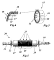
- FIG. 3-5 A possible embodiment is according to Fig. 3-5 as follows:
- the rotor 20 with its rotor shaft 21 and the fans 22, 23 arranged at both ends extends along the rotor axis 16.
- the composite shield material is prefabricated in the form of rings 15 and 25, respectively, in which Assembly in the axial direction via the rotor 20.
- the design with multiple rings 25 along the axial length of the rotor 20 facilitates simplification of manufacture, transport and assembly, holes and slots 29 in the rings 15, 25 and column 30 (in the axial direction
- the magnetizable rotor rings 15, 25 are preferably designed such that increases in the rotor diameter during operation (due to temperature and centrifugal force) are tolerated.
- the magnetic rings (as in 3 and 4 shown) with two materials in two separate layers. This results in an inner ring 17 of magnetizable "composite shield” material (sintered) and an outer ring 18 made of carbon fiber material (baked).
- the preparation can be carried out in the following manner:
- the magnetizable inner ring 17 is sintered from soft magnetic composite shield material under 1100 ° C for about one hour.
- the finished sintered inner ring material is then heat resistant up to 250 ° C.
- the inner ring 17 is coated with epoxy resin-impregnated carbon fiber mats, the fibers mainly in the circumferential direction (Fiber direction 19 in Fig. 4 ) are aligned.
- the carbon fiber composite is baked under pressure at about 170 ° C for 45 minutes.
- the finished ring can then be machined to provide the necessary vent holes and slots (29) for ventilation and reduction of mechanical stresses.
- the inner ring 17 can be provided with axial slots 31 in order to reduce the mechanical stresses during operation, in particular by increasing the temperature and centrifugal forces.
- the rings (cylinder) 25 are pushed over the rotor body, so that they cover the active part of the rotor winding 24.
- the rings (cylinder) 25 are designed constructively to provide them with dowel pins.
Landscapes
- Engineering & Computer Science (AREA)
- Power Engineering (AREA)
- Synchronous Machinery (AREA)
Applications Claiming Priority (1)
| Application Number | Priority Date | Filing Date | Title |
|---|---|---|---|
| CH01154/08A CH699198A1 (de) | 2008-07-24 | 2008-07-24 | Synchronmaschine sowie Verfahren zum Herstellen einer solchen Synchronmaschine. |
Publications (1)
| Publication Number | Publication Date |
|---|---|
| EP2148408A1 true EP2148408A1 (fr) | 2010-01-27 |
Family
ID=39870422
Family Applications (1)
| Application Number | Title | Priority Date | Filing Date |
|---|---|---|---|
| EP09165911A Withdrawn EP2148408A1 (fr) | 2008-07-24 | 2009-07-20 | Agencement de cône plieur pour une imprimante à rouleaux |
Country Status (3)
| Country | Link |
|---|---|
| US (1) | US20100019614A1 (fr) |
| EP (1) | EP2148408A1 (fr) |
| CH (1) | CH699198A1 (fr) |
Families Citing this family (15)
| Publication number | Priority date | Publication date | Assignee | Title |
|---|---|---|---|---|
| US9859728B2 (en) | 2015-09-01 | 2018-01-02 | Dell Products, Lp | System for securing a wireless power pad |
| US10110042B2 (en) * | 2015-09-01 | 2018-10-23 | Dell Products, Lp | Cart for wirelessly recharging mobile computing devices |
| US9912187B2 (en) | 2015-09-01 | 2018-03-06 | Dell Products, Lp | Wireless power transmission antenna with thermally conductive magnetic shield and method therefor |
| US9905359B2 (en) | 2015-09-01 | 2018-02-27 | Dell Products, Lp | Wireless power antenna winding including heat pipe and method therefor |
| US9973027B2 (en) | 2015-09-01 | 2018-05-15 | Dell Products, Lp | Wireless power charging device with rear side magneto isolation marking |
| US9876382B2 (en) | 2015-09-01 | 2018-01-23 | Dell Products, Lp | Peak power caching in a wireless power system |
| US9954388B2 (en) | 2015-09-01 | 2018-04-24 | Dell Products, Lp | Cover system for wireless power pad |
| US9887555B2 (en) | 2015-09-01 | 2018-02-06 | Dell Products, Lp | Articulating receiver for wireless power delivery system |
| US10148115B2 (en) | 2015-09-01 | 2018-12-04 | Dell Products, Lp | Wireless charging pad with natural draft cooling and method therefor |
| US9954387B2 (en) | 2015-09-01 | 2018-04-24 | Dell Products, Lp | Wireless charging pad with interdependent temperature control and method therefor |
| US11139704B2 (en) * | 2016-03-09 | 2021-10-05 | Mitsubishi Heavy Industries Engine & Turbocharger, Ltd. | Salient pole rotor with magnetic pole portions, concave portions and cylindrical cover portion with fiber filament |
| US10476307B2 (en) | 2017-03-13 | 2019-11-12 | Dell Products, Lp | Wireless power system with foreign object detection and method therefor |
| US10361590B2 (en) | 2017-03-13 | 2019-07-23 | Dell Products, Lp | Wireless power system with device specific power configuration and method therefor |
| US10523037B2 (en) | 2017-03-13 | 2019-12-31 | Dell Products, Lp | Thermal management at a wireless power system |
| US12592598B2 (en) * | 2024-03-22 | 2026-03-31 | Borgwarner Luxembourg Automotive Systems Sa | Systems for rotor including composite material |
Citations (4)
| Publication number | Priority date | Publication date | Assignee | Title |
|---|---|---|---|---|
| GB2250642A (en) * | 1990-10-25 | 1992-06-10 | Sundstrand Corp | Preventing leakage through dynamoelectric machine rotor anti-burst sleeve |
| WO1994006193A1 (fr) * | 1992-09-07 | 1994-03-17 | British Nuclear Fuels Plc | Rotor renforce par des fibres |
| EP1124304A2 (fr) | 2000-01-26 | 2001-08-16 | General Electric Company | Dispositif de liaison structurel, conducteur pour un boítier non-métallique d' un rotor |
| US20050264128A1 (en) | 2004-05-26 | 2005-12-01 | General Electric Company | Variable pitch manifold for rotor cooling in an electrical machine |
Family Cites Families (1)
| Publication number | Priority date | Publication date | Assignee | Title |
|---|---|---|---|---|
| US7187096B2 (en) * | 2003-10-06 | 2007-03-06 | General Electric Company | Multi-layer composite rings for machine rotors |
-
2008
- 2008-07-24 CH CH01154/08A patent/CH699198A1/de not_active Application Discontinuation
-
2009
- 2009-07-20 EP EP09165911A patent/EP2148408A1/fr not_active Withdrawn
- 2009-07-22 US US12/507,174 patent/US20100019614A1/en not_active Abandoned
Patent Citations (4)
| Publication number | Priority date | Publication date | Assignee | Title |
|---|---|---|---|---|
| GB2250642A (en) * | 1990-10-25 | 1992-06-10 | Sundstrand Corp | Preventing leakage through dynamoelectric machine rotor anti-burst sleeve |
| WO1994006193A1 (fr) * | 1992-09-07 | 1994-03-17 | British Nuclear Fuels Plc | Rotor renforce par des fibres |
| EP1124304A2 (fr) | 2000-01-26 | 2001-08-16 | General Electric Company | Dispositif de liaison structurel, conducteur pour un boítier non-métallique d' un rotor |
| US20050264128A1 (en) | 2004-05-26 | 2005-12-01 | General Electric Company | Variable pitch manifold for rotor cooling in an electrical machine |
Also Published As
| Publication number | Publication date |
|---|---|
| US20100019614A1 (en) | 2010-01-28 |
| CH699198A1 (de) | 2010-01-29 |
Similar Documents
| Publication | Publication Date | Title |
|---|---|---|
| EP2148408A1 (fr) | Agencement de cône plieur pour une imprimante à rouleaux | |
| DE68914901T2 (de) | Elektrischer Generator mit axialem Feld. | |
| DE602004012340T2 (de) | Turbolader mit elektrischem Hilfsantrieb | |
| EP2242165B1 (fr) | Rotor pour une machine électrique | |
| WO2023099124A1 (fr) | Machine électrique, en particulier moteur d'entraînement électrique pour véhicules automobiles, comprenant un rotor | |
| DE102012221596A1 (de) | Stator mit einer Umspritzung und elektrische Maschine mit dem Stator | |
| DE102012215236A1 (de) | Rotor einer elektrischen Maschine und elektrische Maschine | |
| EP2870681A2 (fr) | Rotor d'un moteur électrique et moteur électrique | |
| CH617545A5 (fr) | ||
| EP2790295A1 (fr) | Rotor pour un moteur à reluctance, procédé de fabrication d'un rotor pour un moteur à reluctance et machine électrique, notamment moteur à reluctance | |
| DE102021111836A1 (de) | Rotor einer elektrischen Rotationsmaschine sowie elektrische Rotationsmaschine | |
| DE2808347C2 (fr) | ||
| WO2020016177A1 (fr) | Machine à réluctance | |
| EP3058640B1 (fr) | Capot d'extrémité de rotor pour générateurs électriques | |
| EP2697892B1 (fr) | Machine asynchrone | |
| EP2417694B1 (fr) | Machine dynamoélectrique | |
| WO2019171219A1 (fr) | Unité rotor et moteur électrique | |
| DE4411032A1 (de) | Einzelmotorischer Antrieb eines schaftlosen Spinnrotors einer Offenend-Spinnmaschine | |
| DE102021104270B4 (de) | Klauenpol-Rotor für eine elektrische Maschine | |
| DE102019118633A1 (de) | Statorkörper für eine elektrische Maschine | |
| DE102015206974A1 (de) | Rotor für eine elektrische Maschine | |
| DE60033786T2 (de) | Selbstverriegelnder keilblock für feldwicklungen | |
| DE102014218542A1 (de) | Geblechter Stator für Axialmagnetlager | |
| DE102014013384A1 (de) | Polträger für einen elektro-mechanischen Energiewandler | |
| EP1783879B1 (fr) | Machine électrique |
Legal Events
| Date | Code | Title | Description |
|---|---|---|---|
| PUAI | Public reference made under article 153(3) epc to a published international application that has entered the european phase |
Free format text: ORIGINAL CODE: 0009012 |
|
| AK | Designated contracting states |
Kind code of ref document: A1 Designated state(s): AT BE BG CH CY CZ DE DK EE ES FI FR GB GR HR HU IE IS IT LI LT LU LV MC MK MT NL NO PL PT RO SE SI SK SM TR |
|
| AX | Request for extension of the european patent |
Extension state: AL BA RS |
|
| 17P | Request for examination filed |
Effective date: 20100713 |
|
| 17Q | First examination report despatched |
Effective date: 20120116 |
|
| STAA | Information on the status of an ep patent application or granted ep patent |
Free format text: STATUS: THE APPLICATION IS DEEMED TO BE WITHDRAWN |
|
| 18D | Application deemed to be withdrawn |
Effective date: 20120201 |