EP2148411A2 - Endwindungs-Phasenisoliervorrichtung mit Führungsdraht-Rückhaltung und Verfahren zur Rückhaltung von Führungsdrähten an dynamoelektrischen Vorrichtungen - Google Patents
Endwindungs-Phasenisoliervorrichtung mit Führungsdraht-Rückhaltung und Verfahren zur Rückhaltung von Führungsdrähten an dynamoelektrischen Vorrichtungen Download PDFInfo
- Publication number
- EP2148411A2 EP2148411A2 EP09009272A EP09009272A EP2148411A2 EP 2148411 A2 EP2148411 A2 EP 2148411A2 EP 09009272 A EP09009272 A EP 09009272A EP 09009272 A EP09009272 A EP 09009272A EP 2148411 A2 EP2148411 A2 EP 2148411A2
- Authority
- EP
- European Patent Office
- Prior art keywords
- end turn
- lead wire
- separating portion
- stator
- phase insulator
- Prior art date
- Legal status (The legal status is an assumption and is not a legal conclusion. Google has not performed a legal analysis and makes no representation as to the accuracy of the status listed.)
- Withdrawn
Links
Images


Classifications
-
- H—ELECTRICITY
- H02—GENERATION; CONVERSION OR DISTRIBUTION OF ELECTRIC POWER
- H02K—DYNAMO-ELECTRIC MACHINES
- H02K3/00—Details of windings
- H02K3/32—Windings characterised by the shape, form or construction of the insulation
- H02K3/38—Windings characterised by the shape, form or construction of the insulation around winding heads, equalising connectors, or connections thereto
-
- H—ELECTRICITY
- H01—ELECTRIC ELEMENTS
- H01B—CABLES; CONDUCTORS; INSULATORS; SELECTION OF MATERIALS FOR THEIR CONDUCTIVE, INSULATING OR DIELECTRIC PROPERTIES
- H01B13/00—Apparatus or processes specially adapted for manufacturing conductors or cables
- H01B13/06—Insulating conductors or cables
- H01B13/065—Insulating conductors with lacquers or enamels
-
- H—ELECTRICITY
- H02—GENERATION; CONVERSION OR DISTRIBUTION OF ELECTRIC POWER
- H02K—DYNAMO-ELECTRIC MACHINES
- H02K15/00—Processes or apparatus specially adapted for manufacturing, assembling, maintaining or repairing of dynamo-electric machines
- H02K15/30—Manufacture of winding connections
- H02K15/33—Connecting winding sections; Forming leads; Connecting leads to terminals
-
- H—ELECTRICITY
- H02—GENERATION; CONVERSION OR DISTRIBUTION OF ELECTRIC POWER
- H02K—DYNAMO-ELECTRIC MACHINES
- H02K3/00—Details of windings
- H02K3/32—Windings characterised by the shape, form or construction of the insulation
- H02K3/34—Windings characterised by the shape, form or construction of the insulation between conductors or between conductor and core, e.g. slot insulation
- H02K3/345—Windings characterised by the shape, form or construction of the insulation between conductors or between conductor and core, e.g. slot insulation between conductor and core, e.g. slot insulation
-
- Y—GENERAL TAGGING OF NEW TECHNOLOGICAL DEVELOPMENTS; GENERAL TAGGING OF CROSS-SECTIONAL TECHNOLOGIES SPANNING OVER SEVERAL SECTIONS OF THE IPC; TECHNICAL SUBJECTS COVERED BY FORMER USPC CROSS-REFERENCE ART COLLECTIONS [XRACs] AND DIGESTS
- Y10—TECHNICAL SUBJECTS COVERED BY FORMER USPC
- Y10T—TECHNICAL SUBJECTS COVERED BY FORMER US CLASSIFICATION
- Y10T29/00—Metal working
- Y10T29/49—Method of mechanical manufacture
- Y10T29/49002—Electrical device making
- Y10T29/49009—Dynamoelectric machine
Definitions
- This invention relates generally to dynamoelectric devices. More specifically, this invention pertains to an end turn phase insulator comprising a tab configured and adapted to prevent stator lead wires from migrating into a bore of a stator and to prevent the lead wires from migrating radially outward beyond one of the windings of the stator.
- dynamoelectric devices comprise lead wires extending from at least one axial end of the stator. Such lead wires are typically subjected to motion relative to the stator caused by the inertia of such leads interacting with vibrations or movement of the dynamoelectric devices. Over time, this can cause the lead wires to migrate relative to the stator. Due to the proximity of typical lead wires to the rotors of dynamoelectric devices, a common failure of dynamoelectric devices results from the lead wires migrating to the point where they make contact with the rotor or other moving parts in the stator bore, which can cause the device to short.
- prior art dynamoelectric devices often include some means of restraining or supporting the lead wires relative to the stator.
- zip ties have been used to prevent or limit lead wire migration.
- zip ties are susceptible to breaking down in certain environments, such as when the dynamoelectric device is exposed to refrigerants or oils.
- U.S. Patent No. 4,328,438 discloses a dynamoelectric device wherein a flap (27) is looped around an end turn and wrapped over the lead wires. Lacing is then used to sandwich the lead wires between the flap and the end turns of the windings of the stator.
- such a flap reduces the occurrence lead wire migration, it does not have any positive stop means for limiting migration of the lead wires radially inwardly to the inner radial surface of the innermost winding. Additionally, such a flap is configured as part of a holder member that is separate from other components of the dynamoelectric device. Such separate components add to the cost, complicate the assembly process of dynamometric devices, and permit assembly without the component installed.
- lead wires Another problem associated with lead wires is caused by the lead wires being positioned too close to the outer diameter of the stator windings. This creates a potential for interference with the housing shells or other components during the assembly or installation of the dynamoelectric devices.
- the present invention overcomes the disadvantages associated with prior art solutions to lead wire migration.
- the present invention does this by incorporating a lead wire restraining tab as part of an end turn phase insulator.
- the tab is folded radially outward such that it wraps over the lead wires and is laced in such a position where it firmly holds the lead wires near the end turn phase insulator. Because the end turn phase insulator is positioned radially between separate wire coils, the tab serves as a means of ensuring that the lead wires cannot migrate radially into the core of the stator or interfere with the housing shell or other components during the assembly or installation of the dynamoelectric device. Additionally, because the tab is configured as part of a end turn insulator, the restraining tab does not appreciably increase production costs nor does it add any significant assembly steps.
- a stator comprises a core, a plurality of wire coils, an end turn phase insulator, and at least one lead wire.
- the core has a plurality of slots that are circumferentially positioned about an axis. The axis defines radial and circumferential directions and opposite first and second axial ends of the stator.
- the wire coils are wound through the slots and form end turns as they wind from one of the slots to another of the slots.
- the end turn phase insulator comprises an end turn separating portion and a lead wire restraining tab. The end turn separating portion is sandwiched radially between at least two of the end turns.
- the at least two end turns are adjacent the first axial end of the stator and comprise an inner end turn and an outer end turn.
- the inner end turn is radially between the outer end turn and the axis.
- the lead wire restraining tab extends from the end turn separating portion and from between the inner end turn and the outer end turn and is partially wrapped over the outer end turn.
- the lead wire extends between the lead wire restraining tab and the outer end turn.
- a method of forming a stator of a dynamoelectric device comprises a step of obtaining a stator core.
- the core has a plurality of slots that are circumferentially positioned about an axis.
- the axis defines radial and circumferential directions and opposite first and second axial ends of the stator.
- the method further comprises winding wire through the slots of the stator core in a manner creating a plurality of wire coils that form end turns as the wire coils wind from one of the slots to another of the slots and in a manner creating a lead wire that extends from a first one of the wire coils.
- the method comprises a step of obtaining an end turn phase insulator.
- the end turn phase insulator comprises an end turn separating portion and a lead wire restraining tab.
- the lead wire restraining tab extends from the end turn separating portion.
- the method comprises sandwiching the end turn separating portion of the end turn phase insulator radially between at least two of the end turns.
- the at least two end turns are adjacent the first axial end of the stator and comprise an inner end turn and an outer end turn.
- the inner end turn is radially between the outer end turn and the axis.
- the method comprises encircling the at least two end turns with lacing in a manner wrapping the lead wire restraining tab at least partially over the outer end turn with the lead wire extending between the lead wire restraining tab and the outer end turn and in a manner holding the lead restraining tab away from the inner end turn.
- an end turn phase insulator comprises a sheet of electrical insulation material.
- the sheet comprises first and second end turn separating portions, at least two elongate connecting portions, and a lead wire restraining tab.
- the first and second end turn separating portions are longitudinally spaced from each other.
- the elongate connecting members extend longitudinally from the first end turn separating portion to the second end turn separating portion.
- the lead wire restraining tab extends from the first end turn separating portion in manner such that the lead wire restraining tab defines a longitudinal end of the sheet.
- the first end turn separating portion has a transverse width, as does the lead wire restraining tab. The transverse width of the lead wire restraining tab is less than the transverse width of the first end turn separating portion.
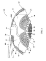
- Figure 1 is a plan view of one embodiment of an end turn phase insulator in accordance with the invention.
- Figure 2 is a perspective view depicting a portion of a stator that incorporates the end turn phase insulator shown in Figure 1 and depicts an intermediate stage of the stator's assembly.
- Figure 3 is a perspective view depicting the stator shown in Figure 2 after the windings of the stator have been laced.
- FIG. 1 An end turn phase insulator 10 in accordance with the invention is shown in Figure 1 .
- the end turn phase insulator 10 is formed out of a thin sheet of electrical insulating material, such as mylar.
- the end turn phase insulator 10 comprises two longitudinally spaced end turn insulating portions 12, two elongate connecting portions 14, and a lead wire restraining tab 16.
- the end turn insulating portions 12 and the two elongate connecting portions 14 are configured in manner similar to corresponding portions of prior art end turn phase insulators.
- the end turn insulating portions 12 of the end turn phase insulator 10 are generally rectangular in shape with rounded corners, although variations from this shape are contemplated as within the scope of embodiments of the invention.
- the elongate connecting portions 14 are parallel to each other and connect the end turn insulating portions 12 to each other.
- a rectangular opening 18 extends through the center of the end turn phase insulator 10 and has a perimeter bound by the end turn insulating portions 12 and the elongate connecting portions 14. As shown, the elongate connecting portions 14 are set-in from the widthwise edges of the end turn insulating portions 12.
- the lead wire restraining tab 16 extends outwardly from one of the end turn insulating portions 12.
- the lead wire restraining tab 16 is significantly narrower in width than are the end turn insulating portions 12.
- the widthwise centerline of lead wire restraining tab 16 coincides with the widthwise centerline of the end turn insulating portions 12, although the restraining tab may be offset from the centerline of the end turn insulating portions without departing from the scope of embodiments of the invention.
- the plan view of the back side of the end turn phase insulator 10 is identical to the plan view of its front side.
- the end turn phase insulator 10 is assembled to a stator in manner similar to the way conventional end turn phase insulators are assembled to stators.
- Figures 2 and 3 show an exemplary stator 20 comprising the end turn phase insulator 10 of Figure 1 .
- the stator 20 comprises a stator core 22, a plurality of windings 24, and lead wires 26.
- the stator core 22 is a typical core of the type that comprises a plurality of parallel slots 30 that are spaced circumferentially from each other about the center axis of the stator's bore 28. The slots extend radially outward into the stator core 22 from the bore 28.
- Coils or windings 24 are added to the stator core 22 by repeatedly winding coated electrically conductive wire 34 through one of the slots 30 in a first axial direction and then back through another of the slots in the opposite axial direction. This creates a plurality of winding end turns 36 on the each of the opposite axial ends of the stator 20.
- the end turn phase insulator 10, and several other end turn insulators 10' that lack the lead wire restraining tab 16, are positioned on the assembly. This is done by inserting the elongate connecting portions 14 of the end turn phase insulator 10 in a pair of the slots 30.
- the end turn phase insulators 10, 10' are arranged such that the their end turn insulating portions 12 slightly overlap circumferentially, as shown in Figure 2 .
- the leads wires 26 are left extending from one or more of the windings 24 on at least one of the axial ends of the stator 20 for the purpose of supplying electrical power to the windings.
- the lead wires 26 are each covered in an insulating sheath, as shown.
- the lead wire 26A shown extending from one of the inner windings 24 is wrapped around the lead wire restraining tab 16 of the end turn phase insulator 10 such that it extends from the winding generally in a first circumferential direction and thereafter turns about the lead wire restraining tab before continuing to extend generally in a second, opposite circumferential direction (see Figure 2 ).
- Another one of the lead wires 26B extends from one of the outer windings 24 in generally in the second circumferential direction, and simply passes behind the restraining tab 16 of the end turn phase insulator 10.
- lacing 40 is then secured to each end of the stator 20.
- the lacing 40 secures the windings 24 to each other so as to prevent the windings from rubbing against each other, which could wear the insulation coating on the wires.
- the lacing 40 is also used to secure lead wire restraining tab 16 of the end turn phase insulator 10 against the adjacent outer winding 24, with the lead wires 26 sandwiched therebetween. This secures the lead wires 26 in the position shown in Figure 3 relative to the remainder of the stator 20. In this position, the lead wires 26 are neither radially interior of the windings 24 nor radially exterior thereto.
- the lead wires 26 will not interfere with other dynamoelectric device components during assembly, such as when the stator 20 is slid into a housing shell, which may be a snug fit. Moreover, because the lead restraining tab 16 extends out from between the inner and outer windings 24, the lead wires 26 are prevented from migrating into the bore 28 of the stator 20. This ensures that the lead wires 26 will not contact the rotor or other moving parts in the bore 28 of the stator 20.
- the invention achieves the several advantages over prior art methods and prior art lead wire restraining devices. It should also be appreciated that multiple end turn phase insulators in accordance with the invention could be used to secure lead wires as they extend around the circumference of a stator. Still further, it should be appreciated that the invention provides for a means of securing the lead wires of a stator simply by modifying one or more of the end turn phase insulators and therefore does not add any appreciable cost to the fabrication of a dynamoelectric device nor does it add any significant assembly steps thereto.
Landscapes
- Engineering & Computer Science (AREA)
- Power Engineering (AREA)
- Manufacturing & Machinery (AREA)
- Insulation, Fastening Of Motor, Generator Windings (AREA)
- Manufacture Of Motors, Generators (AREA)
Applications Claiming Priority (1)
| Application Number | Priority Date | Filing Date | Title |
|---|---|---|---|
| US12/176,651 US8125115B2 (en) | 2008-07-21 | 2008-07-21 | End turn phase insulator with a lead wire restraining tab and method of restraining lead wires on dynamoelectric devices |
Publications (2)
| Publication Number | Publication Date |
|---|---|
| EP2148411A2 true EP2148411A2 (de) | 2010-01-27 |
| EP2148411A3 EP2148411A3 (de) | 2012-10-17 |
Family
ID=41259916
Family Applications (1)
| Application Number | Title | Priority Date | Filing Date |
|---|---|---|---|
| EP09009272A Withdrawn EP2148411A3 (de) | 2008-07-21 | 2009-07-16 | Endwindungs-Phasenisoliervorrichtung mit Führungsdraht-Rückhaltung und Verfahren zur Rückhaltung von Führungsdrähten an dynamoelektrischen Vorrichtungen |
Country Status (4)
| Country | Link |
|---|---|
| US (1) | US8125115B2 (de) |
| EP (1) | EP2148411A3 (de) |
| KR (1) | KR101082278B1 (de) |
| CN (2) | CN101635477A (de) |
Families Citing this family (7)
| Publication number | Priority date | Publication date | Assignee | Title |
|---|---|---|---|---|
| US8907541B2 (en) | 2012-09-25 | 2014-12-09 | Remy Technologies, L.L.C. | Slot liner for electro-dynamic machine |
| US9124158B2 (en) * | 2012-12-21 | 2015-09-01 | Hamilton Sundstrand Corporation | Phase separator insulator for electric machine stator |
| US9369020B2 (en) | 2012-12-21 | 2016-06-14 | Hamilton Sundstrand Corporation | Phase separators for electrical machines |
| US20140306571A1 (en) * | 2013-04-11 | 2014-10-16 | Hamilton Sundstrand Corporation | Pole separator insert for electric machine stator |
| JP6613986B2 (ja) * | 2016-03-25 | 2019-12-04 | 株式会社豊田自動織機 | 電動式流体機械 |
| US10715001B2 (en) * | 2017-06-28 | 2020-07-14 | Hitachi Automotive Systems, Ltd. | Dynamo-Electric Machine |
| US11581775B2 (en) * | 2019-05-14 | 2023-02-14 | Hanon Systems | Device for driving a compressor with an insulation arrangement |
Citations (2)
| Publication number | Priority date | Publication date | Assignee | Title |
|---|---|---|---|---|
| JPS5641739B2 (de) | 1973-06-28 | 1981-09-30 | ||
| GB2088648A (en) | 1980-11-19 | 1982-06-09 | Aspera Spa | Insulating element for electric motor windings |
Family Cites Families (16)
| Publication number | Priority date | Publication date | Assignee | Title |
|---|---|---|---|---|
| US3439205A (en) * | 1966-03-28 | 1969-04-15 | Gen Electric | Multiphase alternating current dynamoelectric machine stator winding and method of disposing the winding in slots of the stator |
| US3575623A (en) | 1970-02-02 | 1971-04-20 | Gen Motors Corp | Winding end turn insulator for a dynamoelectric machine |
| US4328438A (en) | 1973-04-02 | 1982-05-04 | General Electric Company | Holder for overload protector |
| US4250419A (en) | 1973-04-02 | 1981-02-10 | General Electric Company | Holder for overload protector |
| JPS5641739A (en) * | 1979-09-10 | 1981-04-18 | Toshiba Corp | Insulating apparatus of winding connection for electric rotary machine |
| JPS56103940A (en) * | 1980-01-18 | 1981-08-19 | Hitachi Ltd | Insulator for rotary electric machine |
| US4588916A (en) | 1985-01-28 | 1986-05-13 | General Motors Corporation | End turn insulation for a dynamoelectric machine |
| JP2941164B2 (ja) * | 1994-04-28 | 1999-08-25 | 本田技研工業株式会社 | 多相ステータ |
| US6170974B1 (en) | 1997-03-18 | 2001-01-09 | Marathon Electric Manufacturing Corporation | Dynamoelectric machine with distribution of the winding coils for minimizing voltage stresses and method of locating coil locations therefore |
| US6043584A (en) * | 1998-04-22 | 2000-03-28 | Reliance Electric Industrial Company | End turn phase insulator and method of using same |
| US7096566B2 (en) | 2001-01-09 | 2006-08-29 | Black & Decker Inc. | Method for making an encapsulated coil structure |
| JP3895588B2 (ja) | 2001-11-16 | 2007-03-22 | 東芝キヤリア株式会社 | 密閉形圧縮機 |
| JP2004007902A (ja) | 2002-05-31 | 2004-01-08 | Tamagawa Seiki Co Ltd | 回転機の絶縁キャップ構造 |
| CN101017997B (zh) * | 2002-07-12 | 2010-10-13 | 布莱克-德克尔公司 | 一种用于制作电枢的方法 |
| JP4461820B2 (ja) * | 2004-01-30 | 2010-05-12 | トヨタ自動車株式会社 | 相間絶縁紙およびそれを備えた電動機 |
| KR100883599B1 (ko) * | 2007-02-26 | 2009-02-13 | 엘지전자 주식회사 | 모터 |
-
2008
- 2008-07-21 US US12/176,651 patent/US8125115B2/en active Active
-
2009
- 2009-07-16 EP EP09009272A patent/EP2148411A3/de not_active Withdrawn
- 2009-07-21 CN CN200910151465A patent/CN101635477A/zh active Pending
- 2009-07-21 KR KR1020090066155A patent/KR101082278B1/ko active Active
- 2009-07-21 CN CN201310096420.XA patent/CN103227525B/zh active Active
Patent Citations (2)
| Publication number | Priority date | Publication date | Assignee | Title |
|---|---|---|---|---|
| JPS5641739B2 (de) | 1973-06-28 | 1981-09-30 | ||
| GB2088648A (en) | 1980-11-19 | 1982-06-09 | Aspera Spa | Insulating element for electric motor windings |
Also Published As
| Publication number | Publication date |
|---|---|
| CN103227525A (zh) | 2013-07-31 |
| EP2148411A3 (de) | 2012-10-17 |
| CN101635477A (zh) | 2010-01-27 |
| KR20100010025A (ko) | 2010-01-29 |
| US8125115B2 (en) | 2012-02-28 |
| CN103227525B (zh) | 2015-07-08 |
| US20100013349A1 (en) | 2010-01-21 |
| KR101082278B1 (ko) | 2011-11-09 |
Similar Documents
| Publication | Publication Date | Title |
|---|---|---|
| JP5938903B2 (ja) | 電動機 | |
| CN103683615B (zh) | 发夹连接装置和包括其的发夹绕组电机 | |
| US8125115B2 (en) | End turn phase insulator with a lead wire restraining tab and method of restraining lead wires on dynamoelectric devices | |
| JP4636192B2 (ja) | バスリング、及びその取付構造 | |
| US20120038230A1 (en) | Rotating electric machine and production method for rotating electric machine | |
| JP2004320993A (ja) | コアスロット挿入部材を有する固定子組立体 | |
| US20060261691A1 (en) | Rotating electric machine rotor pole crossover | |
| JP6124493B1 (ja) | 内燃機関用回転電機およびそのステータ | |
| US10236735B2 (en) | Electric conductor for coil and rotating electric machine | |
| JP6138360B2 (ja) | 回転電機およびその製造方法 | |
| WO2017110987A1 (ja) | ステータおよび回転電機 | |
| JP2005168289A (ja) | ステータアセンブリ | |
| JP2006187164A (ja) | 回転電機 | |
| US6879083B2 (en) | Generator rotor coil end-turn retention system and method | |
| JP6080964B2 (ja) | 回転電機の固定子 | |
| US11979077B2 (en) | Motor stator and method for manufacturing motor stator | |
| US20150372551A1 (en) | Structure of stator | |
| CN101651372B (zh) | 电机及其卷轴和星状部件 | |
| JP7276499B2 (ja) | ステータおよびステータの製造方法 | |
| US12100993B1 (en) | Outer rotor brushless motor | |
| EP4498577A1 (de) | Rotierende elektrische maschine mit gewickeltem feld | |
| JP6855993B2 (ja) | 回転電機のステータ | |
| JPH11275820A (ja) | 電機子のコンミテータ | |
| JP2023127353A5 (de) | ||
| CN113437844A (zh) | 制造线圈的方法、相应的线圈及制造电机的方法 |
Legal Events
| Date | Code | Title | Description |
|---|---|---|---|
| PUAI | Public reference made under article 153(3) epc to a published international application that has entered the european phase |
Free format text: ORIGINAL CODE: 0009012 |
|
| AK | Designated contracting states |
Kind code of ref document: A2 Designated state(s): AT BE BG CH CY CZ DE DK EE ES FI FR GB GR HR HU IE IS IT LI LT LU LV MC MK MT NL NO PL PT RO SE SI SK SM TR |
|
| AX | Request for extension of the european patent |
Extension state: AL BA RS |
|
| PUAL | Search report despatched |
Free format text: ORIGINAL CODE: 0009013 |
|
| AK | Designated contracting states |
Kind code of ref document: A3 Designated state(s): AT BE BG CH CY CZ DE DK EE ES FI FR GB GR HR HU IE IS IT LI LT LU LV MC MK MT NL NO PL PT RO SE SI SK SM TR |
|
| AX | Request for extension of the european patent |
Extension state: AL BA RS |
|
| RIC1 | Information provided on ipc code assigned before grant |
Ipc: H02K 3/38 20060101AFI20120910BHEP |
|
| 17P | Request for examination filed |
Effective date: 20130417 |
|
| STAA | Information on the status of an ep patent application or granted ep patent |
Free format text: STATUS: THE APPLICATION IS DEEMED TO BE WITHDRAWN |
|
| 18D | Application deemed to be withdrawn |
Effective date: 20140201 |