EP2148522A2 - Agencement d'évaluation des valeurs de mesure d'un convertisseur de valeurs de mesure - Google Patents
Agencement d'évaluation des valeurs de mesure d'un convertisseur de valeurs de mesure Download PDFInfo
- Publication number
- EP2148522A2 EP2148522A2 EP09009310A EP09009310A EP2148522A2 EP 2148522 A2 EP2148522 A2 EP 2148522A2 EP 09009310 A EP09009310 A EP 09009310A EP 09009310 A EP09009310 A EP 09009310A EP 2148522 A2 EP2148522 A2 EP 2148522A2
- Authority
- EP
- European Patent Office
- Prior art keywords
- arrangement according
- transducer
- arrangement
- measured value
- data transmission
- Prior art date
- Legal status (The legal status is an assumption and is not a legal conclusion. Google has not performed a legal analysis and makes no representation as to the accuracy of the status listed.)
- Granted
Links
Images

Classifications
-
- H—ELECTRICITY
- H04—ELECTRIC COMMUNICATION TECHNIQUE
- H04Q—SELECTING
- H04Q9/00—Arrangements in telecontrol or telemetry systems for selectively calling a substation from a main station, in which substation desired apparatus is selected for applying a control signal thereto or for obtaining measured values therefrom
-
- H—ELECTRICITY
- H04—ELECTRIC COMMUNICATION TECHNIQUE
- H04Q—SELECTING
- H04Q2209/00—Arrangements in telecontrol or telemetry systems
- H04Q2209/10—Arrangements in telecontrol or telemetry systems using a centralized architecture
-
- H—ELECTRICITY
- H04—ELECTRIC COMMUNICATION TECHNIQUE
- H04Q—SELECTING
- H04Q2209/00—Arrangements in telecontrol or telemetry systems
- H04Q2209/80—Arrangements in the sub-station, i.e. sensing device
- H04Q2209/82—Arrangements in the sub-station, i.e. sensing device where the sensing device takes the initiative of sending data
Definitions
- the invention relates to an arrangement for evaluating the measured values of a transducer according to the independent claims and to a method for operating such an arrangement according to the independent claims.
- incremental encoders encoders
- encoders convert the input quantity, namely the angle of rotation of, for example, a rotor, into a number of electrical pulses.
- the conversion can be realized for example by means of a turntable with radial permeable slots by opto-electronic scanning. The number of these slots determines the resolution (pulses per revolution).
- Such incremental encoders serve, for example, for determining a rotation angle within a rotation range of 0 to 360 degrees. If you want to detect rotations exceeding 360 degrees, so-called multi-turn encoders (absolute encoders) are known. These include, in addition to the coding disc for the detection of the angular position further Codierusionn to detect even beyond 360 degrees outgoing revolutions.
- resolvers For detecting rotational movements, so-called resolvers are also known.
- the absolute position of the motor shaft is determined by means of a resolver. It consists of a rotor coil and two staggered by 90 degrees stator windings and works on the principle of rotary transformer.
- the resolver in the stator and on the rotor each have an auxiliary winding to ensure a brushless power supply.
- different voltages are induced in the stator windings.
- the voltages at the two stator windings are transformed by the supply voltage and have sinusoidal envelopes.
- the two envelopes are 90 degrees electrically offset from each other and are evaluated in the inverter to zero crossing and amplitude. This determines the absolute rotor position, speed and direction of rotation.
- the aforementioned so-called encoder systems are based on a wide variety of principles and require a wide variety of controls or provide different signal forms. Each type of encoder therefore requires an interface specific to it.
- the publication DE 34 456 17 A1 shows, for example, a method and an arrangement for the serial transmission of the digital measured values of a transducer by means of an interface relevant to the encoder shown here.
- the parallel pending measured values are stored in a parallel-serial shift register and transmitted serially in time with a clock pulse train, which is generated by a processing unit receiving the measurements. This synchronous and serial transmission allows easy processing of the transmitted data and a high baud rate of data transmission.
- drive control devices To control electrical machines, in particular electric servomotors, so-called drive control devices or drive amplifiers are required. These devices supply a three-phase motor with, for example, a three-phase current and simultaneously control the position and the speed using the aforementioned transducer signals.
- the measurement transducers required are arranged on the rotating or moving part of the motor. If such a transducer is used by the device, the overall arrangement can be found in the so-called closed-loop mode. Thus, there is a closed loop and the device continuously processes the signals generated by the transducer in the context of driving the electric servo motor.
- the object of the invention is therefore to realize an arrangement for evaluating the measured values of a transducer, which can be easily integrated into an automation component and which can process a multiplicity of different transducer signals.
- the invention solves this problem by providing a previously mentioned arrangement with an evaluation means and with a connection means for connecting the evaluation means to the transducer, the connection means in turn comprising means which are at least partially configurable such that a connection of the evaluation means per se the measured value data transmission differing transducer is feasible.
- This has the advantage that only a single mechanical interface for connecting the transducer with the arrangement must be provided, which leads to a hardware-saving. The variety of variants and the possible connector combinations are thus reduced to a minimum.
- connection means is configurable with respect to the measured value data transmission by using suitable means, in addition to the already mentioned mechanical universal connection possibility of a transducer also allows the electrical universal connection possibility of a transducer to the arrangement.
- the solution according to the invention has the advantage that a computer program (eg firmware of a drive amplifier) for operating an automation component, which generally comprises the arrangement according to the invention, can be easily expanded by slight modifications, such that the configuration of the arrangement according to the invention also uses the User interface or an HMI (Human Machine Interface) can be done.
- a computer program eg firmware of a drive amplifier
- HMI Human Machine Interface
- a switching possibility between at least one asynchronous and a synchronous measured value data transmission is provided.
- a first data transmission means is preferably provided, which can be switched over between transmission mode and reception mode.
- the flexibility of the arrangement is further increased by providing a second data transmission means for realizing the synchronous measured value data transmission, which is realized in such a way that it can generate a clock, wherein the transmission and reception of measured value data takes place by means of the first data transmission means.
- This embodiment of the arrangement according to the invention makes it possible for the previously mentioned means for asynchronous data transmission to be used for synchronous data transmission by assuming the part of transmitting and receiving measured value data.
- the second data transmission means provides the synchronization clock required for the synchronous data transmission.
- the aforementioned flexibility is further increased by the fact that the data transmission means used are also able to transmit and / or receive data at the same time. It is also achieved with the aforementioned measures that the number of connection pins for the mechanical connection of the transducer to the arrangement can be reduced to a minimum since one and the same Data transmission means for a variety of measured data transmission methods can be used.
- a drive matrix is preferably provided.
- the control matrix could, for example, be stored in the form of a table in a memory.
- the memory could, for example, be a non-volatile memory encompassed by the arrangement according to the invention or a memory encompassed by a drive controller or a drive amplifier, which also simultaneously includes parameters for parameterizing the drive controller or the drive amplifier.
- the above-mentioned table could be organized, for example, from a plurality of rows and columns, wherein, for example, by means of each row a separate measured data transmission method to be supported is defined, and by means of each column the configuration and / or activation required for these data transmission methods is necessary for the realization of the measured data transmission method Means of the arrangement is defined.
- configuration parameters are provided for the configuration.
- These configuration parameters may be implemented in the form of binary codes, for example in the form of 8, 16, 32 or 64-bit words.
- the configuration parameters could, for example, be stored in a memory of the arrangement. By means of the individual bits of these words it is possible.
- the drive means is realized by means of a programmable logic device (FPGA).
- FPGA programmable logic device
- the hardware costs are drastically reduced and the necessary functions can be implemented easily and inexpensively.
- the different communication protocol libraries for carrying out the realization of a communication with the transducer can be stored. Of course, it would also be possible to keep these libraries in a separate memory.
- the arrangement also includes a control voltage generation.
- a resolver can be connected to the arrangement.
- the arrangement can generate an alternating excitation signal which can be transmitted to the resolver and which in turn can be received in the form of two signals separated from one another and phase-shifted and surrounded by an envelope.
- measured values are transmitted according to the following principles: Endat standard, Hyperface standard, SSI standard, rectangular signals (two lanes with reference pulse), sine signals (two lanes with reference pulse), resolver, Panasonic standard.
- Endat standard Hyperface standard
- SSI standard rectangular signals (two lanes with reference pulse), sine signals (two lanes with reference pulse), resolver, Panasonic standard.
- the communication protocols or measured value data transmission principles required for these standards are kept in the arrangement.
- the implementation of the standards is realized by means of a logic which can be encompassed by the programmable logic module and can be executed by means of this logic module.
- the arrangement is implemented in such a way that the supply voltage of the transducer can be measured by means of a single electrical line (sense line), which falls below a configurable threshold value of this supply voltage can be raised again substantially taking into account the measured value up to the threshold. It is assumed that the voltage drop on the supply line to the voltage drop of the ground line (GND) largely corresponds.
- the supply voltage applied to the measured value converter is guided to the arrangement according to the invention, this comprising a voltage regulator, which is adjusted taking into account the substantially doubled measured value (control function), that the desired supply voltage is present at the encoder system taking into account the determined supply voltage deviation from the desired standard value.
- the connecting means preferably comprises a mechanical connecting means for the releasable mechanical connection of the transducer to the evaluation means and a measuring means for detecting the characteristic properties of the measured value of the transducer as well as a digitizing means for digitizing the measured values of the transducer as well as a voltage supply means for generating in particular at least two voltage levels ,
- analog signals can be digitized or measured, reference pulse evaluations can be carried out and a wide variety of supply voltages for measured value converters can be output.
- the inventive interaction of the aforementioned means thus makes it possible to support the aforementioned encoder systems (Endat, SSI, Hyperface, rectangular encoder, sine encoder, Panasonicgeber, resolver, etc.).
- the arrangement according to the invention is preferably comprised of a device for operating an electrical machine, wherein the device comprises a parameter memory, so that the arrangement according to the invention can be parameterized by means of at least one parameter stored in the parameter memory of the device.
- the arrangement according to the invention can thus be parameterized simultaneously and automatically during commissioning as well.
- the object is likewise achieved by means of a method for operating the arrangement, wherein this arrangement automatically establishes a communication connection with the measured value converter, as long as an automatic and continuous selection of communication protocols takes place until a communication connection has been established.
- the arrangement first attempts to record the communication with the encoder system by selecting the various protocols stored in the arrangement and already mentioned above (Endat, Hyperface, Panasonic, etc.).
- This has the advantage that, depending on the result of this connection attempt, further steps can be initiated which are completely automated and independently executable by the arrangement according to the invention.
- an electronic nameplate which is generally encompassed by this measured value system is read out fully automatically by means of the arrangement according to the invention.
- the arrangement according to the invention after reading thus at least the type and the resolution of the encoder system are known.
- the arrangement can thus automatically adapt to this encoder, without manual intervention, for example by maintenance personnel required.
- This solution according to the invention thus helps to save costs and time during repair.
- the arrangement may provide an indication, for example, to the repair personnel, for example by means of an HMI (Human Machine Interface).
- HMI Human Machine Interface
- the repair personnel or an operator of the system must locate the resolution and the characteristic data of the transducer itself (for example, by means of the mechanical nameplate of a sensor) and specify manually via a parameterization interface.
- These parameters can then be stored in the parameter memory of the drive controller, which could include, for example, the arrangement according to the invention, or in a memory of the arrangement according to the invention.
- Parameter memories are generally not volatile memories, so that even after switching off, the parameters entered are always available again without a new input.
- FIG. 1 the arrangement according to the invention is shown roughly schematically with their components.
- the arrangement 10 according to the invention (dashed line) comprises a mechanical connecting means 11 for the releasable mechanical connection of the transducer 12 with the arrangement according to the invention.
- the evaluation device 13 which is used to evaluate the measurement data supplied by the transducer 12, comprises the arrangement 10 according to the invention.
- the evaluation means 13 also prepares the data supplied by the measured value converter 12 such that they can be processed further directly, for example, by a drive control device or a drive amplifier.
- the connection of the evaluation means 13 to the transducer 12 is successful by means of the connecting means 18.
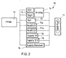
- the connecting means 18 comprises, in addition to a mechanical interface 11, further means 14, 15, 16, 17 a, 17 b for the electrical connection of the evaluation means 13 to the transducer 12 has only the function of electrically connecting the signal transducers 12 outgoing signal lines with the evaluation means 13, whereas the means 14, 15, 16, 17a and 17b connected in parallel between evaluation means 13 and mechanical interface 11, the electrical and thus the signal-side connection of the evaluation means 13 at realize the transducer 12.
- the means 14 serves to detect the characteristic Characteristics of the measured values of the transducer 12. It is used, for example, to measure the signal supplied by the transducer. These can be both analog and digital signals. So that signals can be further processed in digital form, a digitizer 15 is also included.
- the digitizing means 15 receives by means of the mechanical interface 11 analog signals and converts them into a digital form such that they can be further processed by the evaluation means 13 in digital form.
- a voltage supply means 16 which serves for the generation of in particular a plurality of voltage levels. These voltage levels may be, for example, reference voltages required for the operation of the transducer.
- the aforementioned power supply means could also be used to provide a supply voltage to the transducer.
- connection means 18 Also included in the connection means 18 are data transmission means 17a, 17b.
- These transmission means 17a, 17b can be, for example, driver components for communication (for example a plurality of RS485 components).
- All aforementioned means 14, 15, 16, 17a and 17b each occupy one or more connection pins on the mechanical interface 11 and are connected in parallel between the evaluation means 13 and the mechanical interface 11. This means that a simultaneous parallel operation of all means 14 15 16 17a, 17b can be realized. Accordingly, the arrangement can accordingly simultaneously digitize a received analog measurement signal and evaluate a reference signal, for example.
- FIG. 2 shows the arrangement according to the invention somewhat more detailed than the block diagram of FIG. 1 , It is indicated that the evaluation means 13 has been realized in the form of an FPGA (Field Programmable Gata Array).
- All of these aforementioned components / means are arranged in parallel between FPGA 13 and mechanical interface 11 and can be operated in parallel.
- the activation or deactivation and the configuration of these components / means takes place by parameterization by means of parameters stored in a memory (not shown) encompassed by the arrangement.
- the device according to the invention supports up to ten different encoder systems for measured values and is therefore highly flexible.
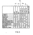
- FIG. 3 shows by way of example how a drive matrix according to the invention could be realized by means of a table.
- FIG. 3 shows the structure and contents of the table.
- the table consists of eight columns relevant for the control and eleven rows relevant for the control.
- Each column represents one of the freely configurable electrical means 14,15,16,17a, b, which are covered by the connecting means 18.
- Each line comprises a possible mode of operation of the arrangement according to the invention.
- it is noted in the table which of the means known from the columns 14, 15, 16, 17a, b of the arrangement according to the invention is necessary for realizing the operating mode defined by the lines.
- two bidirectional RS485 drivers 17a, b are implemented.
- asynchronous communications such as Hiperface and Panasonic
- only one of the two drivers 17a, b is needed.
- the drive direction can be switched over for send and receive operation.
- synchronous communications such as Endat and SSI
- a driver is sent out to send the clock.
- the second driver is used to send and receive the data.
- the direction is switchable accordingly.
- both drivers 17a, b are placed on input to receive the incremental signals. So it is a multiple use of the driver 17 a, b and the connected pins realized on the plug.
- the Panasonic system has an asynchronous interface (UART) with 2.5Mbaud. Communication is realized via an RS485 block (send / receive switching). The levels comply with the RS485 standard. The supply is 5V. The position is read out cyclically by means of the arrangement according to the invention from the encoder system. The evaluation means of the arrangement is communication master.
- the required parameterization of the arrangement according to the invention from the table can be read out for all measured value transducers to be supported, so that the arrangement according to the invention can be parameterized by means of the FGA or any other superordinate logic.
- the columns associated with each transducer principle could easily be represented by an 8-bit word.
- the 8-bit word is represented by the lines assigned to the encoder system. If a bit is set to 1, this may correspond, for example, to an activated means 14, 15, 16, 17 a, b. If, on the other hand, a bit is cleared (set to zero), this could correspond to a deactivation of the means 14, 15, 16, 17a, b. For the eleven measured value converters to be supported, this would require eleven parameters of 8 bits each (11 x 8 bit words).
Landscapes
- Engineering & Computer Science (AREA)
- Computer Networks & Wireless Communication (AREA)
- Arrangements For Transmission Of Measured Signals (AREA)
- Testing Or Calibration Of Command Recording Devices (AREA)
- Control Of Electric Motors In General (AREA)
Applications Claiming Priority (1)
| Application Number | Priority Date | Filing Date | Title |
|---|---|---|---|
| DE102008034318.8A DE102008034318B4 (de) | 2008-07-23 | 2008-07-23 | Anordnung zur Auswertung der Messwerte eines Messwertwandlers |
Publications (3)
| Publication Number | Publication Date |
|---|---|
| EP2148522A2 true EP2148522A2 (fr) | 2010-01-27 |
| EP2148522A3 EP2148522A3 (fr) | 2017-09-13 |
| EP2148522B1 EP2148522B1 (fr) | 2020-09-23 |
Family
ID=41226129
Family Applications (1)
| Application Number | Title | Priority Date | Filing Date |
|---|---|---|---|
| EP09009310.5A Active EP2148522B1 (fr) | 2008-07-23 | 2009-07-17 | Agencement d'évaluation des valeurs de mesure d'un convertisseur de valeurs de mesure |
Country Status (3)
| Country | Link |
|---|---|
| US (1) | US8280691B2 (fr) |
| EP (1) | EP2148522B1 (fr) |
| DE (1) | DE102008034318B4 (fr) |
Cited By (1)
| Publication number | Priority date | Publication date | Assignee | Title |
|---|---|---|---|---|
| CN104142893A (zh) * | 2013-05-10 | 2014-11-12 | 约翰内斯﹒海德汉博士有限公司 | 位置测量装置 |
Families Citing this family (2)
| Publication number | Priority date | Publication date | Assignee | Title |
|---|---|---|---|---|
| IT1402222B1 (it) * | 2010-10-12 | 2013-08-28 | Selex Communications Spa | Metodo per trasmettere valori numerici da una unita' di rilevazione ad una unita' di controllo. |
| CN115683175B (zh) * | 2022-08-24 | 2025-10-28 | 珠海格力电器股份有限公司 | 一种旋转变压器的软件解码电路 |
Citations (1)
| Publication number | Priority date | Publication date | Assignee | Title |
|---|---|---|---|---|
| DE3445617A1 (de) | 1984-07-13 | 1985-07-04 | Max Stegmann GmbH, Uhren- und Elektroapparatefabrik, 7710 Donaueschingen | Verfahren und anordnung zur seriellen uebertragung der digitalen messwerte eines messwertwandlers |
Family Cites Families (17)
| Publication number | Priority date | Publication date | Assignee | Title |
|---|---|---|---|---|
| DE3561846D1 (en) * | 1984-07-13 | 1988-04-14 | Stegmann Uhren Elektro | Arrangement for the serial transmission of measured values of at least one transducer |
| US5488307A (en) * | 1993-12-22 | 1996-01-30 | Namco Controls Corporation | Sensor interface method and apparatus |
| DE59605246D1 (de) * | 1996-02-16 | 2000-06-21 | Heidenhain Gmbh Dr Johannes | Vorrichtung und Verfahren zur Umschaltung zwischen verschiedenen Betriebsmodi eines Messwertaufnehmers |
| US6115654A (en) * | 1997-12-23 | 2000-09-05 | Simmonds Precision Products, Inc. | Universal sensor interface system and method |
| DE19847701C2 (de) * | 1998-10-16 | 2001-11-22 | Pepperl & Fuchs | Verfahren zur Anpassung von busfähigen Geräten an das von einer sendenden Station verwendete Datenübertragungsprotokoll |
| US6571132B1 (en) * | 1999-09-28 | 2003-05-27 | Rosemount Inc. | Component type adaptation in a transducer assembly |
| WO2001044760A1 (fr) * | 1999-12-16 | 2001-06-21 | Siemens Aktiengesellschaft | Circuit et procede de saisie de valeurs mesurees |
| DE10113223A1 (de) * | 2001-03-19 | 2002-10-02 | Siemens Ag | Steuerungssystem für Sprudelbäder |
| DE10130215B4 (de) * | 2001-06-22 | 2007-08-30 | Hottinger Baldwin Messtechnik Gmbh | Meßgrößenaufnehmer mit angeschlossenem Datenspeicher |
| US6792396B2 (en) * | 2002-03-28 | 2004-09-14 | Ge Medical Systems Information Technologies, Inc. | Interface device and method for a monitoring network |
| US20050021712A1 (en) * | 2003-01-24 | 2005-01-27 | Constantin Chassapis | Multi-user, multi-device remote access system |
| DE10306231A1 (de) * | 2003-02-14 | 2004-08-26 | Dr. Johannes Heidenhain Gmbh | Elektronische Zwischenbaugruppe |
| DE10351356A1 (de) * | 2003-11-04 | 2005-06-23 | Siemens Ag | Verfahren zur Identifikation von analogen Messsignalgebern und zugehörige Anordnung |
| DE102004011698B4 (de) * | 2004-03-10 | 2007-12-13 | Siemens Ag | Verfahren zum Erkennen eines Sensortyps |
| DE502006008081D1 (de) * | 2006-06-30 | 2010-11-25 | Sick Ag | Anschlussmodul für Sensoren |
| DE102006030616A1 (de) * | 2006-07-03 | 2008-01-17 | Valeo Schalter Und Sensoren Gmbh | Schnittstellenvorrichtung |
| US7768258B2 (en) * | 2006-09-06 | 2010-08-03 | Metrix Instrument Co., L.P. | Proximity probe transmitter |
-
2008
- 2008-07-23 DE DE102008034318.8A patent/DE102008034318B4/de not_active Expired - Fee Related
-
2009
- 2009-07-17 EP EP09009310.5A patent/EP2148522B1/fr active Active
- 2009-07-22 US US12/507,572 patent/US8280691B2/en active Active
Patent Citations (1)
| Publication number | Priority date | Publication date | Assignee | Title |
|---|---|---|---|---|
| DE3445617A1 (de) | 1984-07-13 | 1985-07-04 | Max Stegmann GmbH, Uhren- und Elektroapparatefabrik, 7710 Donaueschingen | Verfahren und anordnung zur seriellen uebertragung der digitalen messwerte eines messwertwandlers |
Cited By (4)
| Publication number | Priority date | Publication date | Assignee | Title |
|---|---|---|---|---|
| CN104142893A (zh) * | 2013-05-10 | 2014-11-12 | 约翰内斯﹒海德汉博士有限公司 | 位置测量装置 |
| EP2801794A3 (fr) * | 2013-05-10 | 2015-10-28 | Dr. Johannes Heidenhain GmbH | Dispositif de mesure de position |
| CN104142893B (zh) * | 2013-05-10 | 2019-08-23 | 约翰内斯﹒海德汉博士有限公司 | 位置测量装置 |
| US11796313B2 (en) | 2013-05-10 | 2023-10-24 | Dr. Johannes Heidenhain Gmbh | Position-measuring device |
Also Published As
| Publication number | Publication date |
|---|---|
| DE102008034318A1 (de) | 2010-01-28 |
| US8280691B2 (en) | 2012-10-02 |
| EP2148522B1 (fr) | 2020-09-23 |
| EP2148522A3 (fr) | 2017-09-13 |
| DE102008034318B4 (de) | 2019-08-29 |
| US20100023304A1 (en) | 2010-01-28 |
Similar Documents
| Publication | Publication Date | Title |
|---|---|---|
| EP2113742B2 (fr) | Dispositif de mesure doté d'un balayage à deux canaux | |
| EP2335028B1 (fr) | Capteur de rotation multitour | |
| DE102010056524B4 (de) | Tragbares Werkzeug und Verfahren zum Durchführen von Arbeitsvorgängen mit diesem Werkzeug | |
| EP1327119B2 (fr) | Dispositif de mesure de position et procede pour faire fonctionner ce dispositif | |
| EP2216635A1 (fr) | Dispositif de calibrage pour un dispositif de mesure de force et dispositif de mesure de force | |
| DE112008002887T5 (de) | Mehrachsentreiber-Steuerverfahren, Mehrachsentreiber und damit versehenes Mehrachsenantriebs-Steuersystem | |
| DE102017216666A1 (de) | Positionsmesseinrichtung und Verfahren zum Betreiben einer Positionsmesseinrichtung | |
| EP0833130B1 (fr) | Système et procédé de mesure de position | |
| EP1546659B1 (fr) | Systeme de mesure et procede pour controler son fonctionnement | |
| DE102008034318B4 (de) | Anordnung zur Auswertung der Messwerte eines Messwertwandlers | |
| EP0198248B1 (fr) | Dispositif de commande pour un moteur triphasé d'entraînement alimenté par un convertisseur de fréquence | |
| DE69626096T2 (de) | Numerisches steuergerat | |
| DE3782231T2 (de) | Anordnung zum nachweis des rotationsstandes des motorrotors. | |
| EP3964903B1 (fr) | Dispositif et procédé de traitement des valeurs mesurées dépendant de la rotation | |
| DE102012103245A1 (de) | Vereinfachte Inbetriebnahme von Antrieben mit individuellen Motordaten | |
| EP1462771A2 (fr) | Procédé et appareil pour déterminer la position absolue d'un axe d'un détecteur de position | |
| DE4129577C2 (de) | Meßsystem zur Drehwinkelmessung | |
| DE112010000429B4 (de) | Informationsmanagementsystem für eine Antriebsvorrichtung und Verfahren zur Herstellungder Antriebsvorrichtung | |
| DE102007031218B4 (de) | Vorrichtung, Etikettiermaschine und Verfahren zum Betreiben einer Vorrichtung | |
| EP3382348B1 (fr) | Dispositif de mesure de position et procédé de fonctionnement d'un dispositif de mesure de position | |
| WO2003021839A2 (fr) | Transmission de donnees de mesure | |
| EP1614990B1 (fr) | Capteur de position et méthode pour mésurer la position | |
| EP3001271B1 (fr) | Procédé et dispositif destinés à la quantité de mouvement d'un entraînement | |
| EP2469239A1 (fr) | Dispositif de mesure d'angle multi-tours | |
| EP1618440B1 (fr) | Table tournante à roulettes et procédé correspondant pour son opération |
Legal Events
| Date | Code | Title | Description |
|---|---|---|---|
| PUAI | Public reference made under article 153(3) epc to a published international application that has entered the european phase |
Free format text: ORIGINAL CODE: 0009012 |
|
| AK | Designated contracting states |
Kind code of ref document: A2 Designated state(s): AT BE BG CH CY CZ DE DK EE ES FI FR GB GR HR HU IE IS IT LI LT LU LV MC MK MT NL NO PL PT RO SE SI SK SM TR |
|
| AX | Request for extension of the european patent |
Extension state: AL BA RS |
|
| PUAL | Search report despatched |
Free format text: ORIGINAL CODE: 0009013 |
|
| AK | Designated contracting states |
Kind code of ref document: A3 Designated state(s): AT BE BG CH CY CZ DE DK EE ES FI FR GB GR HR HU IE IS IT LI LT LU LV MC MK MT NL NO PL PT RO SE SI SK SM TR |
|
| AX | Request for extension of the european patent |
Extension state: AL BA RS |
|
| RIC1 | Information provided on ipc code assigned before grant |
Ipc: H04Q 9/00 20060101AFI20170808BHEP |
|
| STAA | Information on the status of an ep patent application or granted ep patent |
Free format text: STATUS: REQUEST FOR EXAMINATION WAS MADE |
|
| 17P | Request for examination filed |
Effective date: 20180313 |
|
| RBV | Designated contracting states (corrected) |
Designated state(s): AT BE BG CH CY CZ DE DK EE ES FI FR GB GR HR HU IE IS IT LI LT LU LV MC MK MT NL NO PL PT RO SE SI SK SM TR |
|
| STAA | Information on the status of an ep patent application or granted ep patent |
Free format text: STATUS: EXAMINATION IS IN PROGRESS |
|
| 17Q | First examination report despatched |
Effective date: 20190326 |
|
| RAP1 | Party data changed (applicant data changed or rights of an application transferred) |
Owner name: ROBERT BOSCH GMBH |
|
| GRAP | Despatch of communication of intention to grant a patent |
Free format text: ORIGINAL CODE: EPIDOSNIGR1 |
|
| STAA | Information on the status of an ep patent application or granted ep patent |
Free format text: STATUS: GRANT OF PATENT IS INTENDED |
|
| INTG | Intention to grant announced |
Effective date: 20200625 |
|
| GRAS | Grant fee paid |
Free format text: ORIGINAL CODE: EPIDOSNIGR3 |
|
| GRAA | (expected) grant |
Free format text: ORIGINAL CODE: 0009210 |
|
| STAA | Information on the status of an ep patent application or granted ep patent |
Free format text: STATUS: THE PATENT HAS BEEN GRANTED |
|
| AK | Designated contracting states |
Kind code of ref document: B1 Designated state(s): AT BE BG CH CY CZ DE DK EE ES FI FR GB GR HR HU IE IS IT LI LT LU LV MC MK MT NL NO PL PT RO SE SI SK SM TR |
|
| REG | Reference to a national code |
Ref country code: GB Ref legal event code: FG4D Free format text: NOT ENGLISH |
|
| REG | Reference to a national code |
Ref country code: CH Ref legal event code: EP |
|
| REG | Reference to a national code |
Ref country code: DE Ref legal event code: R096 Ref document number: 502009016276 Country of ref document: DE |
|
| REG | Reference to a national code |
Ref country code: IE Ref legal event code: FG4D Free format text: LANGUAGE OF EP DOCUMENT: GERMAN |
|
| REG | Reference to a national code |
Ref country code: AT Ref legal event code: REF Ref document number: 1317631 Country of ref document: AT Kind code of ref document: T Effective date: 20201015 |
|
| PG25 | Lapsed in a contracting state [announced via postgrant information from national office to epo] |
Ref country code: GR Free format text: LAPSE BECAUSE OF FAILURE TO SUBMIT A TRANSLATION OF THE DESCRIPTION OR TO PAY THE FEE WITHIN THE PRESCRIBED TIME-LIMIT Effective date: 20201224 Ref country code: NO Free format text: LAPSE BECAUSE OF FAILURE TO SUBMIT A TRANSLATION OF THE DESCRIPTION OR TO PAY THE FEE WITHIN THE PRESCRIBED TIME-LIMIT Effective date: 20201223 Ref country code: HR Free format text: LAPSE BECAUSE OF FAILURE TO SUBMIT A TRANSLATION OF THE DESCRIPTION OR TO PAY THE FEE WITHIN THE PRESCRIBED TIME-LIMIT Effective date: 20200923 Ref country code: BG Free format text: LAPSE BECAUSE OF FAILURE TO SUBMIT A TRANSLATION OF THE DESCRIPTION OR TO PAY THE FEE WITHIN THE PRESCRIBED TIME-LIMIT Effective date: 20201223 Ref country code: SE Free format text: LAPSE BECAUSE OF FAILURE TO SUBMIT A TRANSLATION OF THE DESCRIPTION OR TO PAY THE FEE WITHIN THE PRESCRIBED TIME-LIMIT Effective date: 20200923 Ref country code: FI Free format text: LAPSE BECAUSE OF FAILURE TO SUBMIT A TRANSLATION OF THE DESCRIPTION OR TO PAY THE FEE WITHIN THE PRESCRIBED TIME-LIMIT Effective date: 20200923 |
|
| PG25 | Lapsed in a contracting state [announced via postgrant information from national office to epo] |
Ref country code: LV Free format text: LAPSE BECAUSE OF FAILURE TO SUBMIT A TRANSLATION OF THE DESCRIPTION OR TO PAY THE FEE WITHIN THE PRESCRIBED TIME-LIMIT Effective date: 20200923 |
|
| REG | Reference to a national code |
Ref country code: NL Ref legal event code: MP Effective date: 20200923 |
|
| REG | Reference to a national code |
Ref country code: LT Ref legal event code: MG4D |
|
| PG25 | Lapsed in a contracting state [announced via postgrant information from national office to epo] |
Ref country code: EE Free format text: LAPSE BECAUSE OF FAILURE TO SUBMIT A TRANSLATION OF THE DESCRIPTION OR TO PAY THE FEE WITHIN THE PRESCRIBED TIME-LIMIT Effective date: 20200923 Ref country code: CZ Free format text: LAPSE BECAUSE OF FAILURE TO SUBMIT A TRANSLATION OF THE DESCRIPTION OR TO PAY THE FEE WITHIN THE PRESCRIBED TIME-LIMIT Effective date: 20200923 Ref country code: SM Free format text: LAPSE BECAUSE OF FAILURE TO SUBMIT A TRANSLATION OF THE DESCRIPTION OR TO PAY THE FEE WITHIN THE PRESCRIBED TIME-LIMIT Effective date: 20200923 Ref country code: RO Free format text: LAPSE BECAUSE OF FAILURE TO SUBMIT A TRANSLATION OF THE DESCRIPTION OR TO PAY THE FEE WITHIN THE PRESCRIBED TIME-LIMIT Effective date: 20200923 Ref country code: NL Free format text: LAPSE BECAUSE OF FAILURE TO SUBMIT A TRANSLATION OF THE DESCRIPTION OR TO PAY THE FEE WITHIN THE PRESCRIBED TIME-LIMIT Effective date: 20200923 Ref country code: PT Free format text: LAPSE BECAUSE OF FAILURE TO SUBMIT A TRANSLATION OF THE DESCRIPTION OR TO PAY THE FEE WITHIN THE PRESCRIBED TIME-LIMIT Effective date: 20210125 Ref country code: LT Free format text: LAPSE BECAUSE OF FAILURE TO SUBMIT A TRANSLATION OF THE DESCRIPTION OR TO PAY THE FEE WITHIN THE PRESCRIBED TIME-LIMIT Effective date: 20200923 |
|
| PG25 | Lapsed in a contracting state [announced via postgrant information from national office to epo] |
Ref country code: IS Free format text: LAPSE BECAUSE OF FAILURE TO SUBMIT A TRANSLATION OF THE DESCRIPTION OR TO PAY THE FEE WITHIN THE PRESCRIBED TIME-LIMIT Effective date: 20210123 Ref country code: ES Free format text: LAPSE BECAUSE OF FAILURE TO SUBMIT A TRANSLATION OF THE DESCRIPTION OR TO PAY THE FEE WITHIN THE PRESCRIBED TIME-LIMIT Effective date: 20200923 Ref country code: PL Free format text: LAPSE BECAUSE OF FAILURE TO SUBMIT A TRANSLATION OF THE DESCRIPTION OR TO PAY THE FEE WITHIN THE PRESCRIBED TIME-LIMIT Effective date: 20200923 |
|
| REG | Reference to a national code |
Ref country code: DE Ref legal event code: R097 Ref document number: 502009016276 Country of ref document: DE |
|
| PG25 | Lapsed in a contracting state [announced via postgrant information from national office to epo] |
Ref country code: SK Free format text: LAPSE BECAUSE OF FAILURE TO SUBMIT A TRANSLATION OF THE DESCRIPTION OR TO PAY THE FEE WITHIN THE PRESCRIBED TIME-LIMIT Effective date: 20200923 |
|
| PLBE | No opposition filed within time limit |
Free format text: ORIGINAL CODE: 0009261 |
|
| STAA | Information on the status of an ep patent application or granted ep patent |
Free format text: STATUS: NO OPPOSITION FILED WITHIN TIME LIMIT |
|
| PG25 | Lapsed in a contracting state [announced via postgrant information from national office to epo] |
Ref country code: DK Free format text: LAPSE BECAUSE OF FAILURE TO SUBMIT A TRANSLATION OF THE DESCRIPTION OR TO PAY THE FEE WITHIN THE PRESCRIBED TIME-LIMIT Effective date: 20200923 Ref country code: SI Free format text: LAPSE BECAUSE OF FAILURE TO SUBMIT A TRANSLATION OF THE DESCRIPTION OR TO PAY THE FEE WITHIN THE PRESCRIBED TIME-LIMIT Effective date: 20200923 |
|
| 26N | No opposition filed |
Effective date: 20210624 |
|
| PG25 | Lapsed in a contracting state [announced via postgrant information from national office to epo] |
Ref country code: IT Free format text: LAPSE BECAUSE OF FAILURE TO SUBMIT A TRANSLATION OF THE DESCRIPTION OR TO PAY THE FEE WITHIN THE PRESCRIBED TIME-LIMIT Effective date: 20200923 |
|
| REG | Reference to a national code |
Ref country code: CH Ref legal event code: PL |
|
| PG25 | Lapsed in a contracting state [announced via postgrant information from national office to epo] |
Ref country code: MC Free format text: LAPSE BECAUSE OF FAILURE TO SUBMIT A TRANSLATION OF THE DESCRIPTION OR TO PAY THE FEE WITHIN THE PRESCRIBED TIME-LIMIT Effective date: 20200923 |
|
| REG | Reference to a national code |
Ref country code: BE Ref legal event code: MM Effective date: 20210731 |
|
| PG25 | Lapsed in a contracting state [announced via postgrant information from national office to epo] |
Ref country code: LI Free format text: LAPSE BECAUSE OF NON-PAYMENT OF DUE FEES Effective date: 20210731 Ref country code: CH Free format text: LAPSE BECAUSE OF NON-PAYMENT OF DUE FEES Effective date: 20210731 |
|
| PG25 | Lapsed in a contracting state [announced via postgrant information from national office to epo] |
Ref country code: LU Free format text: LAPSE BECAUSE OF NON-PAYMENT OF DUE FEES Effective date: 20210717 |
|
| PG25 | Lapsed in a contracting state [announced via postgrant information from national office to epo] |
Ref country code: IE Free format text: LAPSE BECAUSE OF NON-PAYMENT OF DUE FEES Effective date: 20210717 Ref country code: BE Free format text: LAPSE BECAUSE OF NON-PAYMENT OF DUE FEES Effective date: 20210731 |
|
| REG | Reference to a national code |
Ref country code: AT Ref legal event code: MM01 Ref document number: 1317631 Country of ref document: AT Kind code of ref document: T Effective date: 20210717 |
|
| PG25 | Lapsed in a contracting state [announced via postgrant information from national office to epo] |
Ref country code: AT Free format text: LAPSE BECAUSE OF NON-PAYMENT OF DUE FEES Effective date: 20210717 |
|
| PG25 | Lapsed in a contracting state [announced via postgrant information from national office to epo] |
Ref country code: HU Free format text: LAPSE BECAUSE OF FAILURE TO SUBMIT A TRANSLATION OF THE DESCRIPTION OR TO PAY THE FEE WITHIN THE PRESCRIBED TIME-LIMIT; INVALID AB INITIO Effective date: 20090717 Ref country code: CY Free format text: LAPSE BECAUSE OF FAILURE TO SUBMIT A TRANSLATION OF THE DESCRIPTION OR TO PAY THE FEE WITHIN THE PRESCRIBED TIME-LIMIT Effective date: 20200923 |
|
| PG25 | Lapsed in a contracting state [announced via postgrant information from national office to epo] |
Ref country code: MK Free format text: LAPSE BECAUSE OF FAILURE TO SUBMIT A TRANSLATION OF THE DESCRIPTION OR TO PAY THE FEE WITHIN THE PRESCRIBED TIME-LIMIT Effective date: 20200923 |
|
| PG25 | Lapsed in a contracting state [announced via postgrant information from national office to epo] |
Ref country code: TR Free format text: LAPSE BECAUSE OF FAILURE TO SUBMIT A TRANSLATION OF THE DESCRIPTION OR TO PAY THE FEE WITHIN THE PRESCRIBED TIME-LIMIT Effective date: 20200923 |
|
| PG25 | Lapsed in a contracting state [announced via postgrant information from national office to epo] |
Ref country code: MT Free format text: LAPSE BECAUSE OF FAILURE TO SUBMIT A TRANSLATION OF THE DESCRIPTION OR TO PAY THE FEE WITHIN THE PRESCRIBED TIME-LIMIT Effective date: 20200923 |
|
| PGFP | Annual fee paid to national office [announced via postgrant information from national office to epo] |
Ref country code: GB Payment date: 20240723 Year of fee payment: 16 |
|
| PGFP | Annual fee paid to national office [announced via postgrant information from national office to epo] |
Ref country code: DE Payment date: 20250924 Year of fee payment: 17 |
|
| PGFP | Annual fee paid to national office [announced via postgrant information from national office to epo] |
Ref country code: FR Payment date: 20250723 Year of fee payment: 17 |
|
| GBPC | Gb: european patent ceased through non-payment of renewal fee |
Effective date: 20250717 |
|
| PG25 | Lapsed in a contracting state [announced via postgrant information from national office to epo] |
Ref country code: GB Free format text: LAPSE BECAUSE OF NON-PAYMENT OF DUE FEES Effective date: 20250717 |