EP2148948B1 - Dispositif de tirage et d'étirage de fils multifilaments - Google Patents
Dispositif de tirage et d'étirage de fils multifilaments Download PDFInfo
- Publication number
- EP2148948B1 EP2148948B1 EP08750139A EP08750139A EP2148948B1 EP 2148948 B1 EP2148948 B1 EP 2148948B1 EP 08750139 A EP08750139 A EP 08750139A EP 08750139 A EP08750139 A EP 08750139A EP 2148948 B1 EP2148948 B1 EP 2148948B1
- Authority
- EP
- European Patent Office
- Prior art keywords
- godets
- godet
- guide
- heating
- heating means
- Prior art date
- Legal status (The legal status is an assumption and is not a legal conclusion. Google has not performed a legal analysis and makes no representation as to the accuracy of the status listed.)
- Not-in-force
Links
Images


Classifications
-
- D—TEXTILES; PAPER
- D02—YARNS; MECHANICAL FINISHING OF YARNS OR ROPES; WARPING OR BEAMING
- D02J—FINISHING OR DRESSING OF FILAMENTS, YARNS, THREADS, CORDS, ROPES OR THE LIKE
- D02J13/00—Heating or cooling the yarn, thread, cord, rope, or the like, not specific to any one of the processes provided for in this subclass
- D02J13/005—Heating or cooling the yarn, thread, cord, rope, or the like, not specific to any one of the processes provided for in this subclass by contact with at least one rotating roll
-
- D—TEXTILES; PAPER
- D01—NATURAL OR MAN-MADE THREADS OR FIBRES; SPINNING
- D01D—MECHANICAL METHODS OR APPARATUS IN THE MANUFACTURE OF ARTIFICIAL FILAMENTS, THREADS, FIBRES, BRISTLES OR RIBBONS
- D01D5/00—Formation of filaments, threads, or the like
- D01D5/12—Stretch-spinning methods
- D01D5/16—Stretch-spinning methods using rollers, or like mechanical devices, e.g. snubbing pins
-
- D—TEXTILES; PAPER
- D02—YARNS; MECHANICAL FINISHING OF YARNS OR ROPES; WARPING OR BEAMING
- D02J—FINISHING OR DRESSING OF FILAMENTS, YARNS, THREADS, CORDS, ROPES OR THE LIKE
- D02J1/00—Modifying the structure or properties resulting from a particular structure; Modifying, retaining, or restoring the physical form or cross-sectional shape, e.g. by use of dies or squeeze rollers
- D02J1/22—Stretching or tensioning, shrinking or relaxing, e.g. by use of overfeed and underfeed apparatus, or preventing stretch
- D02J1/224—Selection or control of the temperature during stretching
-
- D—TEXTILES; PAPER
- D02—YARNS; MECHANICAL FINISHING OF YARNS OR ROPES; WARPING OR BEAMING
- D02J—FINISHING OR DRESSING OF FILAMENTS, YARNS, THREADS, CORDS, ROPES OR THE LIKE
- D02J13/00—Heating or cooling the yarn, thread, cord, rope, or the like, not specific to any one of the processes provided for in this subclass
Definitions
- the invention relates to a device for stripping and stretching multifilament threads in a melt spinning process according to the preamble of claim 1.
- the drawing operation in the multifilament threads is assisted by a temperature control of the threads.
- systems are generally known in which the heating of the yarns takes place by means of separate heating means or directly by heated guide shells of the godets.
- a heating means is arranged in the yarn path between two godets.
- the heating means is designed as a heated plate, is guided at the surface at a small distance from the thread.
- the thread is tempered by heat exchange in the form of heat convection and heat conduction.
- the hot plate is heated to a temperature in the range of 250 ° C to 500 ° C.
- Another object of the invention is to provide a generic device for stripping and stretching multifilament threads, in which a plurality of threads is heated as evenly as possible without contact.
- the heating means are formed by a plurality of juxtaposed elongated heat radiation body, which extend substantially parallel to the guide shells of the godets and which are arranged in the bounded by the taut pieces of thread clearance between the guide shells of godets.
- the invention is characterized in that a high radiation density of heat rays for heating the filaments can be generated.
- the entire gap between the guide shells of the godets can be advantageously used to place several heat radiation body side by side in a confined space.
- the high integration of heat between the godets leads to a very compact design.
- the development of the invention in which the heat radiation body are formed by infrared radiation body, is characterized by the fact that the energy transport between the heating means and the multifilament yarns takes place exclusively by an electromagnetic wave radiation. This energy transport is independent of the distance and the environment of the multifilament yarn to the heating medium out.
- the infrared radiation bodies are arranged side by side, wherein the infrared radiation body extending parallel to the guide shells of the godets and in the bounded by the taut pieces of thread clearance between the guilds of godets are arranged.
- the entire gap between the guide shells of the godets can be used advantageously to produce a high radiation density of infrared rays with several infrared radiation bodies and thus to heat the yarn sheet.
- the infrared radiation body passing between the guide shells of the threads heating section having a length of at least 500 mm having.
- the number and choice of the infrared radiation body can also realize greater lengths in the range of> 800 mm.
- in which the infrared radiation bodies can be operated within the heating zone with the same or different jet power
- temperature profiles within the heating zone can advantageously be realized.
- the infrared radiation bodies are preferably formed by heating tubes which are connected to one another to form a heating module and generate heat radiation on two sides, wherein the heating module is arranged in a center plane spanned by the axes of the godets. This allows for multiple wrapping of the guide coats strained between the leaders Heat the thread pieces both on a top side and on a bottom side through the heating tubes.
- the heating tubes are preferably equipped with a Carbonschreibleiter to generate the infrared radiation in the wavelength range of 2 microns to 4 microns.
- the carbon heater can be heated to a temperature of above 1000 ° C in a few seconds.
- the guide casing of the free-running godet in comparison to the guide casing of the driven godet have a smaller or equal diameter.
- the guide shells of both godets can be operated by the electric motors at the same circumferential speeds or with a speed difference generated between the guide shells.
- a godet carrier is provided for holding both godets, which also carries the arranged between the godets heating medium.
- the godet carrier is preferably formed by two spaced-apart longitudinal members, on which the guide shells of both godets are rotatably supported towards both end faces and which are combined with the heating means to form a godet module.
- godet modules represent an assembly that can be used flexibly in a melt spinning process.
- such godet modules can preferably be integrated with horizontally aligned arrangement of the godets and the heating means in an upper platform of a winding machine.
- compact arrangements in a melt spinning process can be realized, which allows the operability of the winding machine and the godet module from an operating level out.
- the two godets are associated with several other godets, which have between them another heating means.
- the heating means is also formed by a plurality of juxtaposed infrared radiation body, which extend substantially parallel to the guide shells of the godets and which are arranged in the bounded by the taut pieces of thread clearance between the guide shells of the godets. In this way, in particular, tempering can also be carried out for so-called relaxation or shrinkage treatment of the threads.
- godets and heating means are preferably combined as separate godet modules and arranged one above the other in a drawing field.
- the godets and the heating means are preferably arranged in a heating chamber.
- the threads are then fed or felt through thread inlets and thread outlets of the heating chamber to the godets.
- the device according to the invention is both suitable for producing so-called preoriented POY yarns or fully drawn FDY yarns.
- the invention will be explained in more detail below with reference to the attached figures with reference to some embodiments of the device according to the invention.
- Fig. 1 and Fig. 2 a first embodiment of the device according to the invention is shown in several views.
- the device is in a cross-sectional view and in Fig. 2 shown in a plan view.
- Fig. 1 the device is in a cross-sectional view
- Fig. 2 shown in a plan view.
- the embodiment has two galette duo with the godets 1.1 and 1.2 and the underlying godets 1.3 and 1.4.
- the godet 1.1 has a guide shell 2.1, the projecting rotatable about a godet axis 11.1 is mounted on a godet carrier 4.1.
- the godet axis 11.1 is rotatably coupled to the guide casing 2.1 and is driven by a godet 14.1.
- the second godet 1.2 is arranged on the godet carrier 4.1.
- the godet 1.2 has a guide casing 2.2, which is rotatably coupled to the godet axis 11.2.
- the godet axis 11.2 is freely rotatably mounted with a projecting end in the godet carrier 4.1.
- the guide casing 2.2 of the godet 1.2 is also provided at a distance arranged guide casing 2.1 of the godet 1.1 with a slight inclination (see. Fig. 1 ) to guide a yarn sheet 3 supplied to the guide casing 2.1 of a plurality of synthetic multifilament yarns in several wraps around the guide shells 2.1 and 2.2.
- a heating means 5.1 is arranged in the space between the guide shells 2.1 and 2.2.
- the heating means 5.1 is formed by a plurality of infrared radiation bodies 6.1, 6.2, 6.3, 6.4 and 6.5.
- the infrared radiation body 6.1 to 6.5 are held in a median plane between the guide shells 2.1 and 2.2, which is spanned by the godet axes 11.1 and 11.2.
- the infrared radiation bodies 6.1 to 6.5 are of identical construction, so that the structure of the infrared radiation bodies is explained using the example of the infrared radiation body 6.1.
- the infrared radiation body 6.1 to 6.5 each have a heating tube 8, in which a carbon heater 9 is arranged.
- the heating tube 8, which is formed as a double tube, has a free end in the region of the projecting end faces of the guide shells 2.1 and 2.2.
- With the opposite end of the heating tube 8 is held on a connection carrier 28 which is fixed to the godet carrier 4.1.
- the connection carrier 28 holds all heating tubes 8 of the infrared radiation body 6.1 to 6.5 and forms a Heating module 7, which is held as a unit replaceable on the godet carrier 4.1.
- the infrared radiation body 6.1 to 6.5 are combined to form a heating section.
- the heating tubes 8 of the infrared radiation bodies 6.1 to 6.5 emit their infrared rays to an upper side 32 and to a lower side 30.
- the guide shells 2.1 and 2.2 of the godets 1.1 and 1.2 extending parallel to the infrared radiation bodies 6.1 to 6.5 at the ends of the heating section are made larger in diameter than the diameter of the heating tubes 8, so that the yarn sheet 3 guided on the guide sheaths 2.1 and 2.2 are guided in each case with the stretched between the guide sheaths 2.1 and 2.2 pieces of thread above or below the infrared radiation body 6.1 to 6.5.
- the yarn pieces of the yarn sheet 3 are thus exposed on the top 32 and on the bottom 30 of the infrared radiation.
- the electromagnetic wave structure generated by the CarbonCloudleiter 9 in the heating tubes 8 are particularly adapted to the polymer material of the thread, so that as many rays are absorbed in the material of the filaments to obtain a heating of the threads.
- the infrared radiation generated by the heating tubes 8 preferably has a spectrum of wavelengths in the range of 2 to 4 ⁇ m.
- the first galette duo with the godets 1.1 and 1.2 is followed by a second galette duo with the godets 1.3 and 1.4.
- the godets 1.3 and 1.4 are identical to the godets 1.1 and 1.2 formed, wherein the guide sheaths 2.3 and 2.4 are projectingly supported rotatably on a second godet carrier 4.2.
- the godet 1.3 is driven by a second godet drive (not shown), wherein the peripheral speed of the guide casing 2.3 with respect to the peripheral speed of the guide casing 2.1 of the godet 1.1 is selected to be larger to obtain a draw of the yarn sheet 3 between the godets 1.1 and 1.3.
- the held on the godet carrier 4.2 second godet 1.4 is freely rotatably mounted with its guide sheath 2.4.
- the guide sheath 2.4 of the godet 1.4 a slight inclination relative to the guide sheath 2.3 in order to lead to the godet duo a multiple wrap the yarn sheet 3 can.
- the guide sheaths 2.3 and 2.4 are arranged vertically below the guide sheaths 2.1 and 2.2, wherein the godets 4.1 and 4.2 are arranged offset from one another, so that the running of the guide sheath 2.2 at a projecting end of the guide sheath 2.2 yarn sheet 3 directly on a bearing end of the guide sheath 2.3 applies.
- a second heating means 5.2 is arranged in the space between the guide sheaths 2.3 and 2.4.
- the heating means 5.2 is identical in construction to the heating means 5.1, so that no further explanation takes place at this point.
- the infra red radiation body 6.1 to 6.5 of the second heating means 5.2 form a second heating section between the godets 1.3 and 1.4.
- the infrared radiation body 6.1 to 6.5 are also attached to this as a heating module 7 via a connection carrier 28 to the godet carrier 4.2.
- the second heating means 5.2 is located in a median plane between the guide sheaths 2.3 and 2.4, so that the thread pieces of the yarn sheet 3 at a top 30 and a bottom 29 are guided with uniform spacing and without contact to the infrared radiation bodies 6.1 to 6.3.
- the yarn sheet 3 is stretched between the godets 1.1 and 1.3.
- the threads of the yarn sheet 3 are first heated by the first heating means 5.1 to a stretching temperature.
- the second heating means 5.2 between the godets 1.3 and 1.4, an aftertreatment, for example for shrinkage release.
- Fig. 1 and 2 illustrated device particularly suitable for producing a fully drawn yarn in a melt spinning process.
- the structural arrangement of the godets 1.1 to 1.4 and arranged between the godets heating means 5.1 and 5.2 is exemplary.
- the leadership coats of a godet can be designed in different sizes or in the same size.
- the number of infrared radiation bodies, which are arranged parallel to the guide shells can be freely selected.
- This heating tubes can be used, which generate only one side of an infrared radiation.
- only the thread pieces on the top or only the thread pieces on the underside between the godets can be tempered.
- the length of the heating section is selectable. Depending on the number of infrared radiators, the lengths in the range of 500 mm to 1,000 mm or above are possible.
- the heating means 5.1 and the godets 1.1 and 1.2 are preferably arranged in a heating chamber, not shown here. This allows the environment to be shielded so that the climatic conditions usually prevailing in a hall have no influence on the heating of the thread.
- FIG. 3 and 4 is a further embodiment of the device according to the invention shown in several views.
- Fig. 3 schematically shows a side view and in Fig. 4 the device is shown in a plan view. Unless an explicit reference is made to one of the figures, the following description applies to both figures.
- Fig. 3 and 4 is essentially identical to the embodiment according to Fig. 1 and 2 , so that only the differences will be explained below and otherwise reference is made to the preceding description.
- each of the godets 1.1 and 1.2 has a rotatable guide casing 2.1 and 2.2.
- the guide casing 2.1 of the godet 1.1 is rotatably connected to a godet axis 11.1, which is mounted to a front side via a rear bearing 13.1 in a side member 10.1 and with a front bearing 12.1 in a second opposite side member 10.2.
- the godet axle 11.1 is coupled to the rear bearing 13.1 with an electric motor 14.1 for driving the guide casing 2.1.
- the guide casing 2.2 of the galette 1.2 is freely rotatably supported on the longitudinal members 10.1 and 10.2 by the bearings 12.2 and 13.2.
- the guide casing 2.2 is held with a slight slope in relation to the guide casing 2.1 of the godet 1.1, to lead a group of yarn in multiple wrapping can.
- the heating means 5.1 is arranged in the space formed by the guide sheaths 2.1 and 2.2 on the one hand and by the side members 10.1 and 10.2 on the other hand.
- the heating means 5.1 is identical to the previous embodiment, so that reference is made to the preceding description.
- the heating module 7 formed by the infrared radiation bodies 6.1 to 6.5 can be connected to each of the side members 10.1 and 10.2.
- a godet module 16 which can be arranged as a structural unit, preferably several in a melt spinning process on each other to deduct and stretch a plurality of mutlifilen threads.
- godet modules can be used for the after-treatment of an already drawn thread. It is essential that the group of threads is heated by infrared radiation without contact between the godets.
- Such godet modules can preferably be combined with winding machines in order to be as compact and easy to use To obtain units for the production of melt-spun threads.
- Fig. 5 an embodiment of a mounting situation of such godet modules shown.
- the winding machine 17 has a machine frame 15, which forms the upper plate 18 and which has the furnishings for a total of four winding units 21.1 to 21.4 to simultaneously wind a four-thread set of threads 3 to coil 26.
- each winding unit 21.1 to 21.4 a deflection roller 20, a traversing device 23, a extending over all winding points pressure roller 24 and two alternately guided in a winding area winding spindle 22.1 and 22.2 provided on which the coils 26 are wound simultaneously.
- a spool revolver 25 is provided, which leads by rotation, the winding spindles 22.1 and 22.2 alternately from the winding area in a changing area.
- a surgegalette 19 is provided, which is held at a front end of the winding machine 17.
- the yarn sheet 3 is guided over the 1971galette 19 and distributed to the individual guide rollers 20 of the winding units 21.1 to 21.2.
- the spinning device can be arranged with a spinning shaft directly above the godet modules 16.1 and 16.2, so that a low overall height of the spinning device is achieved.
- the godet modules 16.1 and 16.2 are attached to one of the side members 10.1 or 10.2 on the module carrier 31, so that the out of a spinning shaft threads of the yarn sheet 3 in a simple manner by a manually guided suction gun on the godets of the godet modules 16.1 and 16.2 can be applied ,
- the Godet modules 16.1 and 16. 2 are usually in a heating chamber (not shown here), which is held on the module carrier 31.
- the yarn sheet 3 can then be fed through thread openings in the heating chamber the godet modules 16.1 and 16.2.
- Fig. 5 illustrated embodiment is preferably used for the production of fully drawn threads. In principle, however, it is also possible to use the device according to the invention for the production of pre-oriented threads.
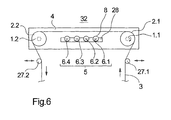
- Fig. 6 an embodiment of the device according to the invention shown, in which the yarn sheet is guided with a Operaumschlingung to the godets.
- the embodiment in Fig. 6 is shown schematically in a side view.
- a godet carrier 4 for example, the godet carrier of the embodiment according to Fig. 1 and Fig. 2 is similar, two godets 1.1 and 1.2 are spaced apart.
- the godet 1.1 has a guide casing 2.1 and the godet 1.2 the guide casing 2.2. Both guide shells 2.1 and 2.2 are driven by electric motors, not shown here.
- a heating means 5 is provided, which is formed in total by four infrared radiation body 6.1 to 6.4.
- the infrared radiation bodies 6.1 to 6.4 are aligned parallel to the guide sheaths 2.1 and 2.2 and held as heating tubes 8 on a connection carrier 28.
- the heating tubes 8 have a radiation outlet facing an upper side 32, so that the yarn section of the yarn sheet 3 stretched between the guide sheaths 2.1 and 2.2 is heated by the infrared radiation of the infrared radiation bodies 6.1 to 6.4.
- the deflection rollers 27.1 and 27.2 are preferably designed to be adjustable, so that the degree of wrap around the godets 1.1 and 1.2 can be selected.
- the in the Fig. 1 to 6 illustrated embodiments of the device according to the invention are characterized in particular by the fact that the guide shells of the godets are unheated.
- the heating of the threads takes place contactless exclusively by an energy transfer in the form of electromagnetic waves.
- a high radiation density is generated, which leads to intensive heating of the threads even with short heating sections and high thread speeds.
- the heating means also form by elongated heat radiation body, for example, have an electrically heated radiation surface to produce the heat radiation.
- heat radiation body are well known, so that no further explanation takes place at this point.
- the radiation surfaces which may be formed for example from a metal, have a high surface temperature of preferably greater than 200 ° C.
Landscapes
- Engineering & Computer Science (AREA)
- Textile Engineering (AREA)
- Mechanical Engineering (AREA)
- Yarns And Mechanical Finishing Of Yarns Or Ropes (AREA)
- Spinning Methods And Devices For Manufacturing Artificial Fibers (AREA)
Claims (15)
- Dispositif de tirage et d'étirage de fils multifilaires dans un processus de filage à l'état fondu avec au moins deux galettes (1.1, 1.2) agencées à distance l'une à l'autre, avec des enveloppes de guidage rotatives (2.1, 2.2) et avec un moyen de chauffage (5.1) agencé entre les galettes (1.1, 2.2), les fils étant guidés sur les enveloppes de guidage (2.1, 2.2) des galettes (1.1, 1.2) avec un enlacement ou une pluralité d'enlacements, les fils étant chauffés par le moyen de chauffage (51) sur leurs tronçons de fils supportés entre les galettes (1.1, 1.2), caractérisé en ce que le moyen de chauffage (5.1) est formé par une pluralité de corps oblongs agencés les uns à coté des autres à rayonnement thermique (6.1 - 6.5) qui s'étendent sensiblement de façon parallèle par rapport aux enveloppes de guidage (2.1, 2.2) des galettes (1.1, 1.2) et qui sont agencés dans l'espace libre limité par les tronçons de fil entre les enveloppes de guidage (2.1, 2.2) des galettes (1.1, 1.2).
- Dispositif selon la revendication 1, caractérisé en ce que les corps à rayonnement thermique sont formés comme des corps à rayonnement infrarouge (6.1 - 6.5).
- Dispositif selon la revendication 2, caractérisé en ce que les corps à rayonnement infrarouge (6.1-6.5) sont agencés entre les enveloppes de guidage (2.1, 2.2) pour former un trajet de chauffage parcouru par les fils, lequel trajet de chauffage a une longueur > 500 mm.
- Dispositif selon la revendication 3, caractérisé en ce qu'à l'intérieur du trajet de chauffage les corps à rayonnement infrarouge (6.1-6.5) sont opérables avec la même puissance rayonnée ou une puissance rayonnée différente.
- Dispositif selon l'une des revendications 2 à 4, caractérisé en ce que les corps à rayonnement infrarouge (6.1 - 6.5) sont formés par des tubes de chauffage (8) qui sont reliés les uns aux autres en un module de réchauffement (7) et qui génèrent de la radiation thermique sur deux cotés et en ce que le module de réchauffement (7) est agencé dans un plan médian qui est formé par les axes (11.1, 11.2) des galettes (1.1, 1.2).
- Dispositif selon la revendication 5, caractérisé en ce que pour générer le rayonnement infrarouge les tubes de chauffage (8) ont respectivement un conducteur chauffant en carbone (9).
- Dispositif selon l'une des revendications 1 à 6, caractérisé en ce que l'enveloppe de guidage (2.1) d'une des galettes (1.1) est entraînée par un moteur électrique (14.1), l'enveloppe de guidage (2.2) de la galette associée (1.2) étant montée en rotation libre par rapport à l'enveloppe de guidage (2.1) de la galette entraînée (1.1).
- Dispositif selon la revendication 7, caractérisé en ce que l'enveloppe de guidage (2.2) de la galette en rotation libre (1.2) a en comparaison avec l'enveloppe de guidage (2.1) de la galette entraînée (1.1) un diamètre plus petit ou le même.
- Dispositif selon l'une des revendications 1 à 8, caractérisé en ce que les enveloppes de guidage (2.1, 2.2) des deux galettes (1.1, 1.2) sont entraînées par des moteurs électriques séparés (14.1, 14.2).
- Dispositif selon l'une des revendications 1 à 9, caractérisé en ce qu'un support de galettes (4.1) pour retenir les deux galettes (1.1, 1.2) est prévu, qui supporte le moyen de chauffage (5.1) agencé entre les galettes (1.1, 1.2).
- Dispositif selon la revendication 10, caractérisé en ce que le support de galettes est formé par deux supports longitudinaux (10.1, 10.2) agencés à distance l'un par rapport à l'autre, sur lesquels les enveloppes de guidage (2.1, 2.2) des deux galettes (1.1, 1.2) sont montées de manière rotative sur les deux faces frontales et lesquels sont combinés avec le moyen de chauffage (5.1) en un module de galette (16).
- Dispositif selon la revendication 11, caractérisé en ce que les galettes (1.1, 1.2) et le moyen de chauffage (5.1) sont agencés en agencement orienté horizontalement par rapport au module de galettes (16.1) et en ce que le module de galettes (16.1, 16.2) est agencé sur une plateforme supérieure (18) d'une machine à embobiner (17).
- Dispositif selon l'une des revendications 1 à 12, caractérisé en ce qu'une pluralité d'autres galettes (1.3, 1.4) sont associées aux deux galettes (1.1, 1.2), au moins un autre moyen de chauffage (5.2) étant prévu entre les galettes (1.3, 1.4), lequel est formé par une pluralité de corps au rayonnement infrarouge (6.1 - 6.5) agencés de manière adjacente, qui s'étendent sensiblement de façon parallèle par rapport au enveloppes de guidage (2.3, 2.4) des galettes (1.3, 1.4) et qui sont agencés dans l'espace libre limité par les tronçons de fils entre les enveloppes de guidage (2.3, 2.4) des galettes (1.3, 1.4).
- Dispositif selon la revendication 13, caractérisé en ce que les galettes (1.1 -1.4) et les moyens de chauffage (5.1, 5.2) sont combinés respectivement en des modules de galettes séparés (16.1, 16.2) par une pluralité de supports de galettes (4.1, 4.2) et en ce que les modules de galettes (16.1, 16.2) sont agencés l'un au dessus de l'autre.
- Dispositif selon l'une des revendications précédentes, caractérisé en ce que les galettes (1.1, 1.2) et le moyen de chauffage (5.1, 5.2) sont agencés dans une chambre de chauffage.
Applications Claiming Priority (2)
| Application Number | Priority Date | Filing Date | Title |
|---|---|---|---|
| DE102007023723A DE102007023723A1 (de) | 2007-05-22 | 2007-05-22 | Vorrichtung zum Abziehen und Verstrecken multifiler Fäden |
| PCT/EP2008/055618 WO2008141940A1 (fr) | 2007-05-22 | 2008-05-07 | Dispositif d'extrusion et d'étirage de fils multifilaments |
Publications (2)
| Publication Number | Publication Date |
|---|---|
| EP2148948A1 EP2148948A1 (fr) | 2010-02-03 |
| EP2148948B1 true EP2148948B1 (fr) | 2011-07-06 |
Family
ID=39708427
Family Applications (1)
| Application Number | Title | Priority Date | Filing Date |
|---|---|---|---|
| EP08750139A Not-in-force EP2148948B1 (fr) | 2007-05-22 | 2008-05-07 | Dispositif de tirage et d'étirage de fils multifilaments |
Country Status (5)
| Country | Link |
|---|---|
| EP (1) | EP2148948B1 (fr) |
| CN (1) | CN101680137A (fr) |
| AT (1) | ATE515587T1 (fr) |
| DE (1) | DE102007023723A1 (fr) |
| WO (1) | WO2008141940A1 (fr) |
Families Citing this family (6)
| Publication number | Priority date | Publication date | Assignee | Title |
|---|---|---|---|---|
| CN103484958B (zh) * | 2013-09-22 | 2016-03-30 | 中国纺织科学研究院 | 牵伸丝用热箱和牵伸丝用加热系统 |
| CN103741234B (zh) * | 2013-12-29 | 2016-03-30 | 大连华阳化纤科技有限公司 | 一种牵伸器的加热箱 |
| CN107904681B (zh) * | 2016-05-27 | 2020-01-17 | 嘉兴昌新差别化纤维科技有限公司 | 带拉伸结构的纺丝装置 |
| CN109537167A (zh) * | 2018-12-10 | 2019-03-29 | 天鼎丰聚丙烯材料技术有限公司 | 断丝处理装置及纺粘无纺布生产装置 |
| CN113718390A (zh) * | 2021-08-31 | 2021-11-30 | 中国纺织科学研究院有限公司 | 一种红外辐射牵伸热箱 |
| CN114323942B (zh) * | 2021-12-24 | 2024-07-12 | 东台弘乐纺织品有限公司 | 一种亚麻制备用棉条牵引拉伸装置 |
Family Cites Families (5)
| Publication number | Priority date | Publication date | Assignee | Title |
|---|---|---|---|---|
| JPH0397914A (ja) | 1989-09-11 | 1991-04-23 | Unitika Ltd | ポリエステル繊維とその製造法 |
| DE19610763A1 (de) | 1996-03-19 | 1997-09-25 | Zinser Textilmaschinen Gmbh | Beheizte Galette zum Erwärmen synthetischer Fäden |
| IT1285328B1 (it) * | 1996-05-16 | 1998-06-03 | T M T Di Manenti & C Sas | Apparecchio per l'imbozzimatura di fili di ordito. |
| WO2006058667A1 (fr) * | 2004-12-01 | 2006-06-08 | Saurer Gmbh & Co. Kg | Procede et dispositif de guidage et de tourbillonnement d'un fil multfilament |
| EP2007935B1 (fr) * | 2006-04-05 | 2013-08-21 | Oerlikon Textile GmbH & Co. KG | Procede et dispositif d'extraction et d'etirage d'un fil multifilament |
-
2007
- 2007-05-22 DE DE102007023723A patent/DE102007023723A1/de not_active Withdrawn
-
2008
- 2008-05-07 AT AT08750139T patent/ATE515587T1/de active
- 2008-05-07 EP EP08750139A patent/EP2148948B1/fr not_active Not-in-force
- 2008-05-07 WO PCT/EP2008/055618 patent/WO2008141940A1/fr not_active Ceased
- 2008-05-07 CN CN200880016154A patent/CN101680137A/zh active Pending
Also Published As
| Publication number | Publication date |
|---|---|
| EP2148948A1 (fr) | 2010-02-03 |
| DE102007023723A1 (de) | 2008-11-27 |
| CN101680137A (zh) | 2010-03-24 |
| WO2008141940A1 (fr) | 2008-11-27 |
| ATE515587T1 (de) | 2011-07-15 |
Similar Documents
| Publication | Publication Date | Title |
|---|---|---|
| EP2007935B1 (fr) | Procede et dispositif d'extraction et d'etirage d'un fil multifilament | |
| EP2283173B1 (fr) | Procédé de tirage et d'étirage d'un fil multifilament lors du filage à l'état fondu, et dispositif destiné à la réalisation du procédé | |
| EP1527217B1 (fr) | Dispositif de filage et d'enroulement | |
| EP3036361B1 (fr) | Dispositif permettant de filer une pluralité de fils synthetiques | |
| EP2456912A1 (fr) | Procédé pour enlever et étirer un fil synthétique, et dispositif pour la mise en oeuvre de ce procédé | |
| EP2598678B1 (fr) | Dispositif pour le filage à chaud, l'étirage et le bobinage de plusieurs fils multifilaments | |
| EP2148948B1 (fr) | Dispositif de tirage et d'étirage de fils multifilaments | |
| DE102013220442A1 (de) | Verstreckungsvorrichtung für gesponnene Fäden | |
| WO2015185245A1 (fr) | Procédé et dispositif de traction et d'étirement d'une pluralité de fils venant d'être filés | |
| EP2358932B1 (fr) | Dispositif pour texturer et enrouler plusieurs fils | |
| WO2015049316A1 (fr) | Dispositif de tirage et bobinage d'une nappe de fils | |
| EP2527502B1 (fr) | Dispositif d'enlèvement et d'étirage d'un fil synthétique | |
| EP2534285B1 (fr) | Dispositif destiné à tirer et enrouler une pluralité de fils synthétiques | |
| EP1523592B1 (fr) | Machine de texturation par fausse torsion | |
| EP2049714A2 (fr) | Machine à texturer | |
| WO2019025263A1 (fr) | Dispositif de production de fils synthétiques | |
| WO2019030134A1 (fr) | Dispositif pour retirer et enrouler une nappe de fils | |
| WO2014173765A1 (fr) | Machine de texturation par fausse torsion | |
| DE102007024765A1 (de) | Vorrichtung zum Verstecken mehrerer Fäden | |
| WO2002052078A1 (fr) | Ensemble galette et dispositif pour etirer un fil | |
| DE102013005457A1 (de) | Vorrichtung zum Schmelzspinnen, Verstrecken und Aufwickeln mehrer synthetischer Fäden | |
| DE102008039378A1 (de) | Verfahren zum Abziehen und Verstrecken eines multifilen Fadens beim Schmelzspinnen sowie eine Vorrichtung zur Durchführung des Verfahrens | |
| EP4298273A1 (fr) | Installation de fabrication de fil | |
| WO2016096405A1 (fr) | Système pour texturer un fil synthétique | |
| DE102007040215A1 (de) | Vorrichtung zum Führen und Erwärmen synthetischer Fäden oder Fasern |
Legal Events
| Date | Code | Title | Description |
|---|---|---|---|
| PUAI | Public reference made under article 153(3) epc to a published international application that has entered the european phase |
Free format text: ORIGINAL CODE: 0009012 |
|
| 17P | Request for examination filed |
Effective date: 20091104 |
|
| AK | Designated contracting states |
Kind code of ref document: A1 Designated state(s): AT BE BG CH CY CZ DE DK EE ES FI FR GB GR HR HU IE IS IT LI LT LU LV MC MT NL NO PL PT RO SE SI SK TR |
|
| AX | Request for extension of the european patent |
Extension state: AL BA MK RS |
|
| 17Q | First examination report despatched |
Effective date: 20100504 |
|
| DAX | Request for extension of the european patent (deleted) | ||
| RTI1 | Title (correction) |
Free format text: DEVICE FOR TAKING UP AND STRETCHING MULTIFILAMENT THREADS |
|
| GRAP | Despatch of communication of intention to grant a patent |
Free format text: ORIGINAL CODE: EPIDOSNIGR1 |
|
| GRAS | Grant fee paid |
Free format text: ORIGINAL CODE: EPIDOSNIGR3 |
|
| GRAA | (expected) grant |
Free format text: ORIGINAL CODE: 0009210 |
|
| AK | Designated contracting states |
Kind code of ref document: B1 Designated state(s): AT BE BG CH CY CZ DE DK EE ES FI FR GB GR HR HU IE IS IT LI LT LU LV MC MT NL NO PL PT RO SE SI SK TR |
|
| REG | Reference to a national code |
Ref country code: GB Ref legal event code: FG4D Free format text: NOT ENGLISH |
|
| REG | Reference to a national code |
Ref country code: CH Ref legal event code: EP |
|
| REG | Reference to a national code |
Ref country code: IE Ref legal event code: FG4D Free format text: LANGUAGE OF EP DOCUMENT: GERMAN |
|
| REG | Reference to a national code |
Ref country code: DE Ref legal event code: R096 Ref document number: 502008004131 Country of ref document: DE Effective date: 20110825 |
|
| REG | Reference to a national code |
Ref country code: NL Ref legal event code: VDEP Effective date: 20110706 |
|
| PG25 | Lapsed in a contracting state [announced via postgrant information from national office to epo] |
Ref country code: SI Free format text: LAPSE BECAUSE OF FAILURE TO SUBMIT A TRANSLATION OF THE DESCRIPTION OR TO PAY THE FEE WITHIN THE PRESCRIBED TIME-LIMIT Effective date: 20110706 |
|
| PG25 | Lapsed in a contracting state [announced via postgrant information from national office to epo] |
Ref country code: FI Free format text: LAPSE BECAUSE OF FAILURE TO SUBMIT A TRANSLATION OF THE DESCRIPTION OR TO PAY THE FEE WITHIN THE PRESCRIBED TIME-LIMIT Effective date: 20110706 Ref country code: HR Free format text: LAPSE BECAUSE OF FAILURE TO SUBMIT A TRANSLATION OF THE DESCRIPTION OR TO PAY THE FEE WITHIN THE PRESCRIBED TIME-LIMIT Effective date: 20110706 Ref country code: PT Free format text: LAPSE BECAUSE OF FAILURE TO SUBMIT A TRANSLATION OF THE DESCRIPTION OR TO PAY THE FEE WITHIN THE PRESCRIBED TIME-LIMIT Effective date: 20111107 Ref country code: IS Free format text: LAPSE BECAUSE OF FAILURE TO SUBMIT A TRANSLATION OF THE DESCRIPTION OR TO PAY THE FEE WITHIN THE PRESCRIBED TIME-LIMIT Effective date: 20111106 Ref country code: NL Free format text: LAPSE BECAUSE OF FAILURE TO SUBMIT A TRANSLATION OF THE DESCRIPTION OR TO PAY THE FEE WITHIN THE PRESCRIBED TIME-LIMIT Effective date: 20110706 Ref country code: LT Free format text: LAPSE BECAUSE OF FAILURE TO SUBMIT A TRANSLATION OF THE DESCRIPTION OR TO PAY THE FEE WITHIN THE PRESCRIBED TIME-LIMIT Effective date: 20110706 Ref country code: NO Free format text: LAPSE BECAUSE OF FAILURE TO SUBMIT A TRANSLATION OF THE DESCRIPTION OR TO PAY THE FEE WITHIN THE PRESCRIBED TIME-LIMIT Effective date: 20111006 Ref country code: SE Free format text: LAPSE BECAUSE OF FAILURE TO SUBMIT A TRANSLATION OF THE DESCRIPTION OR TO PAY THE FEE WITHIN THE PRESCRIBED TIME-LIMIT Effective date: 20110706 |
|
| REG | Reference to a national code |
Ref country code: IE Ref legal event code: FD4D |
|
| PG25 | Lapsed in a contracting state [announced via postgrant information from national office to epo] |
Ref country code: GR Free format text: LAPSE BECAUSE OF FAILURE TO SUBMIT A TRANSLATION OF THE DESCRIPTION OR TO PAY THE FEE WITHIN THE PRESCRIBED TIME-LIMIT Effective date: 20111007 Ref country code: LV Free format text: LAPSE BECAUSE OF FAILURE TO SUBMIT A TRANSLATION OF THE DESCRIPTION OR TO PAY THE FEE WITHIN THE PRESCRIBED TIME-LIMIT Effective date: 20110706 Ref country code: CY Free format text: LAPSE BECAUSE OF FAILURE TO SUBMIT A TRANSLATION OF THE DESCRIPTION OR TO PAY THE FEE WITHIN THE PRESCRIBED TIME-LIMIT Effective date: 20110706 Ref country code: PL Free format text: LAPSE BECAUSE OF FAILURE TO SUBMIT A TRANSLATION OF THE DESCRIPTION OR TO PAY THE FEE WITHIN THE PRESCRIBED TIME-LIMIT Effective date: 20110706 |
|
| PG25 | Lapsed in a contracting state [announced via postgrant information from national office to epo] |
Ref country code: IE Free format text: LAPSE BECAUSE OF FAILURE TO SUBMIT A TRANSLATION OF THE DESCRIPTION OR TO PAY THE FEE WITHIN THE PRESCRIBED TIME-LIMIT Effective date: 20110706 Ref country code: SK Free format text: LAPSE BECAUSE OF FAILURE TO SUBMIT A TRANSLATION OF THE DESCRIPTION OR TO PAY THE FEE WITHIN THE PRESCRIBED TIME-LIMIT Effective date: 20110706 Ref country code: CZ Free format text: LAPSE BECAUSE OF FAILURE TO SUBMIT A TRANSLATION OF THE DESCRIPTION OR TO PAY THE FEE WITHIN THE PRESCRIBED TIME-LIMIT Effective date: 20110706 |
|
| PLBE | No opposition filed within time limit |
Free format text: ORIGINAL CODE: 0009261 |
|
| STAA | Information on the status of an ep patent application or granted ep patent |
Free format text: STATUS: NO OPPOSITION FILED WITHIN TIME LIMIT |
|
| PG25 | Lapsed in a contracting state [announced via postgrant information from national office to epo] |
Ref country code: EE Free format text: LAPSE BECAUSE OF FAILURE TO SUBMIT A TRANSLATION OF THE DESCRIPTION OR TO PAY THE FEE WITHIN THE PRESCRIBED TIME-LIMIT Effective date: 20110706 Ref country code: RO Free format text: LAPSE BECAUSE OF FAILURE TO SUBMIT A TRANSLATION OF THE DESCRIPTION OR TO PAY THE FEE WITHIN THE PRESCRIBED TIME-LIMIT Effective date: 20110706 |
|
| 26N | No opposition filed |
Effective date: 20120411 |
|
| PG25 | Lapsed in a contracting state [announced via postgrant information from national office to epo] |
Ref country code: DK Free format text: LAPSE BECAUSE OF FAILURE TO SUBMIT A TRANSLATION OF THE DESCRIPTION OR TO PAY THE FEE WITHIN THE PRESCRIBED TIME-LIMIT Effective date: 20110706 |
|
| PGFP | Annual fee paid to national office [announced via postgrant information from national office to epo] |
Ref country code: DE Payment date: 20120625 Year of fee payment: 5 Ref country code: CH Payment date: 20120530 Year of fee payment: 5 |
|
| REG | Reference to a national code |
Ref country code: DE Ref legal event code: R097 Ref document number: 502008004131 Country of ref document: DE Effective date: 20120411 |
|
| PGFP | Annual fee paid to national office [announced via postgrant information from national office to epo] |
Ref country code: IT Payment date: 20120521 Year of fee payment: 5 |
|
| BERE | Be: lapsed |
Owner name: OERLIKON TEXTILE G.M.B.H. & CO. KG Effective date: 20120531 |
|
| PG25 | Lapsed in a contracting state [announced via postgrant information from national office to epo] |
Ref country code: MC Free format text: LAPSE BECAUSE OF NON-PAYMENT OF DUE FEES Effective date: 20120531 |
|
| GBPC | Gb: european patent ceased through non-payment of renewal fee |
Effective date: 20120507 |
|
| PG25 | Lapsed in a contracting state [announced via postgrant information from national office to epo] |
Ref country code: BE Free format text: LAPSE BECAUSE OF NON-PAYMENT OF DUE FEES Effective date: 20120531 |
|
| REG | Reference to a national code |
Ref country code: FR Ref legal event code: ST Effective date: 20130131 |
|
| PG25 | Lapsed in a contracting state [announced via postgrant information from national office to epo] |
Ref country code: FR Free format text: LAPSE BECAUSE OF NON-PAYMENT OF DUE FEES Effective date: 20120531 Ref country code: GB Free format text: LAPSE BECAUSE OF NON-PAYMENT OF DUE FEES Effective date: 20120507 Ref country code: ES Free format text: LAPSE BECAUSE OF FAILURE TO SUBMIT A TRANSLATION OF THE DESCRIPTION OR TO PAY THE FEE WITHIN THE PRESCRIBED TIME-LIMIT Effective date: 20111017 |
|
| PG25 | Lapsed in a contracting state [announced via postgrant information from national office to epo] |
Ref country code: BG Free format text: LAPSE BECAUSE OF FAILURE TO SUBMIT A TRANSLATION OF THE DESCRIPTION OR TO PAY THE FEE WITHIN THE PRESCRIBED TIME-LIMIT Effective date: 20111006 |
|
| PG25 | Lapsed in a contracting state [announced via postgrant information from national office to epo] |
Ref country code: MT Free format text: LAPSE BECAUSE OF FAILURE TO SUBMIT A TRANSLATION OF THE DESCRIPTION OR TO PAY THE FEE WITHIN THE PRESCRIBED TIME-LIMIT Effective date: 20110706 |
|
| REG | Reference to a national code |
Ref country code: CH Ref legal event code: PL |
|
| PG25 | Lapsed in a contracting state [announced via postgrant information from national office to epo] |
Ref country code: DE Free format text: LAPSE BECAUSE OF NON-PAYMENT OF DUE FEES Effective date: 20131203 Ref country code: CH Free format text: LAPSE BECAUSE OF NON-PAYMENT OF DUE FEES Effective date: 20130531 Ref country code: LI Free format text: LAPSE BECAUSE OF NON-PAYMENT OF DUE FEES Effective date: 20130531 |
|
| PG25 | Lapsed in a contracting state [announced via postgrant information from national office to epo] |
Ref country code: IT Free format text: LAPSE BECAUSE OF NON-PAYMENT OF DUE FEES Effective date: 20130507 |
|
| REG | Reference to a national code |
Ref country code: DE Ref legal event code: R119 Ref document number: 502008004131 Country of ref document: DE Effective date: 20131203 |
|
| PG25 | Lapsed in a contracting state [announced via postgrant information from national office to epo] |
Ref country code: TR Free format text: LAPSE BECAUSE OF FAILURE TO SUBMIT A TRANSLATION OF THE DESCRIPTION OR TO PAY THE FEE WITHIN THE PRESCRIBED TIME-LIMIT Effective date: 20110706 |
|
| PG25 | Lapsed in a contracting state [announced via postgrant information from national office to epo] |
Ref country code: LU Free format text: LAPSE BECAUSE OF NON-PAYMENT OF DUE FEES Effective date: 20120507 |
|
| REG | Reference to a national code |
Ref country code: AT Ref legal event code: MM01 Ref document number: 515587 Country of ref document: AT Kind code of ref document: T Effective date: 20130507 |
|
| PG25 | Lapsed in a contracting state [announced via postgrant information from national office to epo] |
Ref country code: HU Free format text: LAPSE BECAUSE OF FAILURE TO SUBMIT A TRANSLATION OF THE DESCRIPTION OR TO PAY THE FEE WITHIN THE PRESCRIBED TIME-LIMIT Effective date: 20080507 |
|
| PG25 | Lapsed in a contracting state [announced via postgrant information from national office to epo] |
Ref country code: AT Free format text: LAPSE BECAUSE OF NON-PAYMENT OF DUE FEES Effective date: 20130507 |