EP2149042B1 - Bewertungsverfahren zur bewertung eines überwachungselements für die verwendung in einem farbstoff-penetrationsverfahren - Google Patents
Bewertungsverfahren zur bewertung eines überwachungselements für die verwendung in einem farbstoff-penetrationsverfahren Download PDFInfo
- Publication number
- EP2149042B1 EP2149042B1 EP08755815.1A EP08755815A EP2149042B1 EP 2149042 B1 EP2149042 B1 EP 2149042B1 EP 08755815 A EP08755815 A EP 08755815A EP 2149042 B1 EP2149042 B1 EP 2149042B1
- Authority
- EP
- European Patent Office
- Prior art keywords
- image
- monitoring element
- procedure
- condition
- rating
- Prior art date
- Legal status (The legal status is an assumption and is not a legal conclusion. Google has not performed a legal analysis and makes no representation as to the accuracy of the status listed.)
- Active
Links
Images

Classifications
-
- G—PHYSICS
- G01—MEASURING; TESTING
- G01N—INVESTIGATING OR ANALYSING MATERIALS BY DETERMINING THEIR CHEMICAL OR PHYSICAL PROPERTIES
- G01N21/00—Investigating or analysing materials by the use of optical means, i.e. using sub-millimetre waves, infrared, visible or ultraviolet light
- G01N21/84—Systems specially adapted for particular applications
- G01N21/88—Investigating the presence of flaws or contamination
- G01N21/91—Investigating the presence of flaws or contamination using penetration of dyes, e.g. fluorescent ink
-
- G—PHYSICS
- G01—MEASURING; TESTING
- G01N—INVESTIGATING OR ANALYSING MATERIALS BY DETERMINING THEIR CHEMICAL OR PHYSICAL PROPERTIES
- G01N21/00—Investigating or analysing materials by the use of optical means, i.e. using sub-millimetre waves, infrared, visible or ultraviolet light
- G01N21/84—Systems specially adapted for particular applications
- G01N21/88—Investigating the presence of flaws or contamination
- G01N21/93—Detection standards; Calibrating baseline adjustment, drift correction
Definitions
- the present invention relates to a method, for evaluating, hereafter rating, a calibration element, hereafter monitoring element, for use in a colour penetration method, hereafter dye penetrant procedure.
- the document US 2007/0097360 A1 relates to a method of diagnosing or determining parameters for an installation for detecting open defects in the surfaces of parts by sweating, the method comprising passing at least one standard testpiece through the installation, the testpiece having a surface possessing at least one pattern representative of the type of defect that is to be detected, applying to the surface of the testpiece a penetrating composition including an indicator substance, washing, drying, applying to the surface of the testpiece a composition including a developer, and illuminating the surface of the testpiece to illuminate any remaining indicator substance so as to form a developed image of the or each pattern and deduce therefrom an indication about the quality of the operation of the installation.
- the standard testpiece Prior to passing through the installation, the standard testpiece is subjected to preparatory treatment comprising immersion in a bath containing an emulsifier, a first rinse under pressure, drying, applying a developer at the location(s) of the pattern(s), and a second rinse under pressure.
- a migrating penetrant which fluoresces when irradiated with uv is deposited on the surface of the workpiece to be tested.
- the penetrant deposition is in the form of spraying the workpiece with a penetrant, also dipping it into a bath of penetrant.
- the penetrant After the penetrant has been deposited, it is allowed for a given dwell time to migrate into defects in the material, said defects being open toward the surface, this process being caused by adhesion and capillary effects. After said predetermined dwell time, the workpiece is washed in a manner precisely defined by such boundary conditions as duration, water pressure and water temperature to avert excessively washing the penetrant.
- the stage of "bleeding" begins.
- the penetrant that had been situated in the defects open at the surface will migrate back to and on the workpiece's surface.
- This procedure is frequently optimized/enhanced by depositing a developer at said worpkpiece's surface.
- said developer may be a fine-grain powder or a solution which when dried leaves behind powdery residues.
- the penetrant diffuses into the developer.
- the surface flaws and defects are detected using an uv lamp.
- a monitoring element - which is fitted itself with artificial defects such as star-shaped defects or other, similarly deposited surface damages to be detected - is subjected at regular intervals to the same process as are the workpieces to be tested.
- This monitoring element then is sanctioned by a technician or checking operator who simultaneously also may be charged with carrying out workpiece quality control using uv light. If the artificial defects are clearly visible, this fact is manually logged by the checking operator into a book. If said defects are not sufficiently visible, the process parameters of dye penetrant treatment must be adjusted accordingly. This fact also is manually logged by the checking operator.
- This objective of the present invention is attained by a method rating a monitoring element of a dye penetrant procedure defined in claim 1.
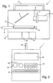
- an apparatus 1 that is configured for carrying out the inventive method rates a test element 2 to which a dye penetrant procedure may be applied or already was and which is fitted with at least one artificial defect open toward the surface of the monitoring element 2 in the form of an indentation, said apparatus 1 comprising an image recorder in the form of a CCD camera 3 fitted with an objective lens 4.
- the CCD camera 3 and lens 4 together generate an image of at least parts of the monitoring element 2, said parts at least comprising one artificial defect.
- the monitoring element 2 may comprise five star-shaped indentations with different line widths, all said five stellate defects being detected by the CCD camera 3 which is fitted with a USB interface.
- an insertion slide 5 which may be pulled out of the apparatus 1 as if it were a drawer to allow receiving the monitoring element 2 and then is reinserted.
- a recess 6 in said slide 5 receives the monitoring element 2 and assures it remains firmly in position on the slide 5.
- the dimensions of the recess are such that the monitoring element 2 can be placed in it and be simultaneously held firmly in position.
- an illuminator 7 which may consist of circularly arrayed uv LEDs. Obviously other light sources may be used alternatively, for instance circularly arrayed mercury or xenon vapor lamps.
- a circular array is not mandatory either, however this configuration of the illuminator 7 around the zone of the lens 4 of the CCD camera 3 eliminates stop interferences (backlighting, scattered light etc.) when generating the images.
- the apparatus 1 is fitted with an image analyzer rating the image generated by the CCD camera 3.
- the image analyzer includes an image comparator 8 comparing the image generated by the image recorder 3 with a reference image.
- the image analyzer may comprise line sequence means rating the image generated by image recorder using a line sequence algorithm for detecting or filtering out lines, i.e., edges or series of adjacent pixels, that have a predetermined contrast to the background. Further components of the image analyzer based for instance on a classifying algorithm or other image rating procedures also are conceivable and applicable.
- the CCD camera which may be black and white or color
- other cameras are applicable also, for instance an interlaced camera, progressive scan camera, CMOS camera (which is able to process high contrasts), or a digital camera.
- the camera and also the image analyzer may be fitted with an IEEE or a RS232 or a serial or parallel interface, or a network or a wireless interface.
- the CCD camera 3 may be integrated for instance using a grabber element (grabber card) or a fire-wire interface.
- said apparatus moreover is fitted with a deflecting mirror 9 deflecting the image of the horizontal monitoring element into the objective 4 (also horizontal) of the CCD camera 3.
- This configuration offers compact positioning of the control element 2 and the CCD camera 3.
- the image comparator 8 includes a reference image memory 10 allowing storing at least one reference image serving as the reference image for the image comparator 8. Moreover the apparatus 1 includes a logging unit 11 to log the images generated by the image recorder 3 and the ratings from the image analyzer, as a result of which a log of the operation of the apparatus 1 may be retrieved any time.
- the apparatus 1 was designed to automatically rate the monitoring element 2 and also is portable (carrying grip 12), allowing carrying said apparatus from one test station where a dye penetrant procedure is applied to the next test station where such a method shall be applied.
- a rating method of the present invention to rate a monitoring element 2 for a dye penetrant procedure may take place as follows (also see the flow chart of Fig. 3 ).
- the dye penetrant procedure is carried out in a first stage (a) at the monitoring element 2.
- the monitoring element 2 together with workpieces to be tested is subjected to the dye penetrant procedure.
- the CCD camera 3 Following this dye penetrant procedure and a selection of the type of monitoring element by means key board 13 configured at the front side of the apparatus 1, and upon insertion of the monitoring element 2 in the receiving slide 5 - and after a manual release using the keyboard 13 - then, in a stage (b), the CCD camera 3 generates an image, hereinafter also referred to as "second image", of at least part of the monitoring element 2 displaying at least a portion of an artificial defect.
- the entire zone comprising the five star-shaped indentations are recorded by the CCD camera 3.
- the second image generated by the CCD camera 3 is rated by an image analyzer of which the output indicates the condition of the monitoring element.
- the stage (c) includes comparing, by means of the image comparator 8, a second image generated by the CCD camera 3 with a corresponding reference image, hereinafter also referred to as "second" reference image.
- the second reference image is an image of the same portion of a monitoring element of the same model, of which the condition must be rated, and which offers an optimal defect detection.
- the comparison is with an image of which the artificial defects are optimally displayed by the previously applied dye penetrant procedure. This shall be the case in the preferred mode of implementation when the five stars configured at the monitoring element are optimally visible under uv light.
- a light 14 (which is green in the preferred embodiment mode) lights up at the front side ( Fig. 2 ) indicating the procedure is OK. If however the output is unsatisfactory, a red light 15 lights up (NG) indicating that the dye penetrant procedure parameters must be changed/altered.
- an image is generated not only following the dye penetrant procedure applied to the monitoring element 2, but also prior to it (stage [0]).
- stage [0] The same portion of the monitoring element 2 is involved that shall be illuminated subsequently to the application of the dye penetrant procedure.
- the cleansed monitoring element 2 is again inserted by the insertion slide into the apparatus 1 and, following manual release, using the keyboard 13, shall be photographed by the CCD camera 3.
- first image of the control element 2
- said first image is rated (step [0']) by the image analyzer, in the form of the image comparator 8, to ascertain in this manner the degree of cleanliness of this monitoring element 2.
- This procedure assures the absence of any previous penetrant residues at the monitoring element 2 before it shall be subjected to the dye penetrant procedure. If said degree of cleanliness is within a predetermined range of quality, then this condition is displayed by the green lamp 14, namely the dye penetrant procedure may be now be applied, whereas in the other case the red light indicates that the monitoring element 2 must be cleansed. Once cleansed, said monitoring element must again be subjected to the stages (0) and (0').
- the stage of image analysis prior to the dye penetrant procedure also includes comparing the first image generated by the image recorder, respectively the CCD camera 3, with a first reference image, using the image comparator 8.
- the comparison takes place with that reference image which is fitted with optimally configured five stars.
- the decision criterion is the magnitude of the difference between the two images, whereas the decision on the condition of the monitoring element 2 after it was subjected to the dye penetrant procedure is determined by the largest possible congruence.
- the reference image is that of a clean monitoring element 2.
- the reference image(s) is/are recorded/stored in the image comparator.
- this log is a memory that can be linked to a computer network. Also this memory can be connected to a portable or fixed printer allowing log printout and if need be electronic forwarding.
Landscapes
- Physics & Mathematics (AREA)
- Health & Medical Sciences (AREA)
- Life Sciences & Earth Sciences (AREA)
- Chemical & Material Sciences (AREA)
- Analytical Chemistry (AREA)
- Biochemistry (AREA)
- General Health & Medical Sciences (AREA)
- General Physics & Mathematics (AREA)
- Immunology (AREA)
- Pathology (AREA)
- Investigating Materials By The Use Of Optical Means Adapted For Particular Applications (AREA)
Claims (3)
- Bewertungsverfahren zur Bewertung eines Überwachungselements (2) für die Verwendung in einem Farbstoff-Penetrationsverfahren, wobei das Überwachungselement mit mindestens einem künstlichen Defekt in Form mindestens einer Einkerbung versehen ist, wobei das Verfahren die folgenden Schritte umfasst:(i) vor Anwendung eines Farbstoff-Penetrationsverfahrens auf das Überwachungselement (2): Erzeugen eines ersten Bildes mindestens von Teilen des Überwachungselements (2), die mindestens Abschnitte des Minimums von einem künstlichen Defekt enthalten, mithilfe eines Bildaufzeichnungsgeräts (3); Bewerten des ersten vom Bildaufzeichnungsgerät (3) erzeugten Bildes mithilfe eines Bildanalysators, wobei der Bewertungsschritt den Schritt des Vergleichens des vom Bildaufzeichnungsgerät (3) erzeugten Bildes mit einem ersten Referenzbild mithilfe eines Bildkomparators (8) beinhaltet, wobei dieser Vergleichsschritt ferner Überprüfen eines Sauberkeitsgrades des Überwachungselements (2) beinhaltet, indem die Größe der Differenz zwischen dem ersten vom Bildaufzeichnungsgerät erzeugten Bild und dem ersten Referenzbild verglichen wird, um zu analysieren, ob der Sauberkeitsgrad des Überwachungselements (2) innerhalb eines vorbestimmten Qualitätsbereichs liegt, wobei das erste Referenzbild ein Referenzbild eines sauberen Überwachungselements (2) ist;(ii) wenn der Sauberkeitsgrad des Überwachungselements (2) innerhalb eines vorbestimmten Qualitätsbereichs liegt: Anzeigen dieses Zustands auf einer Anzeigeeinheit (14, 15, 16), was darauf hinweist, zu Schritt (iii) überzugehen;
wenn der Sauberkeitsgrad des Überwachungselements (2) nicht innerhalb eines vorbestimmten Qualitätsbereichs liegt: Anzeigen dieses Zustands auf einer Anzeigeeinheit (14, 15, 16), was darauf hinweist, dass das Überwachungselement (2) vor dem Übergehen zu Schritt (iii) gereinigt werden muss;(iii) Anwenden eines Farbstoff-Penetrationsverfahrens auf das Überwachungselement (2) und nach Anwenden des Farbstoff-Penetrationsverfahrens auf das Überwachungselement (2): Erzeugen eines zweiten Bildes mindestens von Teilen des Überwachungselements (2), die mindestens Abschnitte des Minimums von einem künstlichen Defekt enthalten, mithilfe eines Bildaufzeichnungsgeräts (3); Bewerten des zweiten vom Bildaufzeichnungsgerät (3) erzeugten Bildes mithilfe des Bildanalysators, wobei der Bewertungsschritt den Schritt des Vergleichens des vom Bildaufzeichnungsgerät (3) erzeugten zweiten Bildes mit mindestens einem zweiten Referenzbild mithilfe eines Bildkomparators (8) beinhaltet, wobei dieser Vergleichsschritt ferner Überprüfen des Zustands des Überwachungselements (2) beinhaltet, indem das zweite vom Bildaufzeichnungsgerät erzeugte Bild und das mindestens eine zweite Referenzbild verglichen werden, um zu analysieren, ob der Zustand des Überwachungselements (2) angemessen ist, um mit der Anwendung des Farbstoff-Penetrationsverfahrens auf Werkstücke mit denselben Parametern fortzufahren, wobei mindestens ein zweites Referenzbild ein Referenzbild ist, das den mindestens einen künstlichen Defekt durch ein zuvor angewandtes Farbstoff-Penetrationsverfahrens optimal zeigt; wobei beim Überprüfen des Zustands des Überwachungselements (2) die Entscheidung durch die größtmögliche Kongruenz bestimmt wird,(iv) wenn der Zustand des Überwachungselements (2) angemessen ist, um mit der Anwendung des Farbstoff-Penetrationsverfahrens auf Werkstücke mit denselben Parametern fortzufahren: Anzeigen dieses Zustands auf der Anzeigeeinheit (14, 15, 16);
wenn der Zustand des Überwachungselements (2) nicht angemessen ist, um mit der Anwendung des Farbstoff-Penetrationsverfahrens auf Werkstücke mit denselben Parametern fortzufahren: Anzeigen dieses Zustands auf der Anzeigeeinheit (14, 15, 16), was darauf hinweist, dass die Parameter des Farbstoff-Penetrationsverfahrens geändert werden müssen. - Verfahren nach Anspruch 1, wobei mindestens ein Referenzbild im Bildkomparator (8) aufgezeichnet oder gespeichert wird.
- Verfahren nach Anspruch 1 oder 2, wobei mindestens das im Bildaufzeichnungsgerät (3) erzeugte Bild und/oder die vom Bildanalysator erlangte Bewertung in ein Protokoll (11) eingetragen werden.
Applications Claiming Priority (2)
| Application Number | Priority Date | Filing Date | Title |
|---|---|---|---|
| DE102007024059.9A DE102007024059B4 (de) | 2007-05-22 | 2007-05-22 | Vorrichtung und Verfahren zur Beurteilung eines Kontrollkörpers bei einem Farb-Eindring-Verfahren |
| PCT/US2008/064036 WO2008147747A1 (en) | 2007-05-22 | 2008-05-19 | Device and method for evaluation of a calibration element used in a colour penetration method |
Publications (2)
| Publication Number | Publication Date |
|---|---|
| EP2149042A1 EP2149042A1 (de) | 2010-02-03 |
| EP2149042B1 true EP2149042B1 (de) | 2017-10-04 |
Family
ID=39708349
Family Applications (1)
| Application Number | Title | Priority Date | Filing Date |
|---|---|---|---|
| EP08755815.1A Active EP2149042B1 (de) | 2007-05-22 | 2008-05-19 | Bewertungsverfahren zur bewertung eines überwachungselements für die verwendung in einem farbstoff-penetrationsverfahren |
Country Status (4)
| Country | Link |
|---|---|
| US (1) | US8335370B2 (de) |
| EP (1) | EP2149042B1 (de) |
| DE (1) | DE102007024059B4 (de) |
| WO (1) | WO2008147747A1 (de) |
Families Citing this family (3)
| Publication number | Priority date | Publication date | Assignee | Title |
|---|---|---|---|---|
| GB2514180A (en) * | 2013-05-17 | 2014-11-19 | Nanomex Ltd | An optical inspection system |
| DE102014216857A1 (de) * | 2014-08-25 | 2016-02-25 | Illinois Tool Works Inc. | Tragbare Materialprüfvorrichtung mit Dokumentationsfunktion |
| FR3153890A1 (fr) * | 2023-10-05 | 2025-04-11 | Safran Aircraft Engines | Installation pour vérifier la conformité d’un contrôle d’une pièce par ressuage |
Citations (2)
| Publication number | Priority date | Publication date | Assignee | Title |
|---|---|---|---|---|
| EP1096249A2 (de) * | 1999-10-26 | 2001-05-02 | Hitachi, Ltd. | Verfahren und Vorrichtung zur zerstörungsfreien Prüfung |
| US20020154811A1 (en) * | 2001-02-09 | 2002-10-24 | Hitachi, Ltd. | Method for non-destructive inspection, apparatus thereof and digital camera system |
Family Cites Families (13)
| Publication number | Priority date | Publication date | Assignee | Title |
|---|---|---|---|---|
| DE3030280C2 (de) * | 1980-08-09 | 1984-02-09 | MTU Motoren- und Turbinen-Union München GmbH, 8000 München | Testkörper zur Überprüfung der Anzeigeempfindlichkeit eines Eindringstoffprüfmittels |
| DE3144379C2 (de) * | 1981-11-07 | 1987-01-02 | Carl Schenck Ag, 6100 Darmstadt | Verfahren zur Durchführung von Rißuntersuchungen und Prüfkörper zur Durchführung des Verfahrens |
| US4621193A (en) * | 1984-11-21 | 1986-11-04 | Michael Van Hoye | Fluorescent penetrant crack detection |
| DE8608690U1 (de) * | 1986-03-29 | 1987-08-06 | Tiede GmbH + Co Rissprüfanlagen, 7087 Essingen | Vorrichtung zur Selbstkontrolle einer optoelektronischen Rissprüfvorrichtung |
| DE3602395C2 (de) * | 1986-01-28 | 1995-06-22 | Tiede Gmbh & Co Risspruefanlagen | Verfahren zur Selbstkontrolle einer optoelektronischen Rißerkennungsvorrichtung |
| GB8702130D0 (en) * | 1987-01-30 | 1987-03-04 | Sira Ltd | Surface inspection |
| DD270143A1 (de) * | 1988-03-16 | 1989-07-19 | Zwickau Ing Hochschule | Verfahren zur pruefung von penetrierfluessigkeiten fuer die zerstoerungsfreie werkstoffpruefung und testkoerper zur durchfuehrung des verfahrens |
| DE3907732A1 (de) * | 1989-03-10 | 1990-09-13 | Isotopenforschung Dr Sauerwein | Verfahren zum ueberwachen einer vorrichtung zum automatischen feststellen und auswerten von oberflaechenrissen |
| JP3417721B2 (ja) * | 1995-04-04 | 2003-06-16 | 三菱電機株式会社 | 走査プローブ顕微鏡の使用方法 |
| DE19645377C2 (de) * | 1996-11-04 | 1998-11-12 | Tiede Gmbh & Co Risspruefanlagen | Rißprüfanlage für Werkstücke nach dem Farbeindringverfahren und Verfahren zur automatischen Rißerkennung |
| DE19902525C2 (de) * | 1999-01-22 | 2001-03-22 | Tiede Gmbh & Co Kg Risspruefan | Verfahren zur automatischen Fehlererkennung bei der Rißprüfung nach dem Farbeindringverfahren |
| US6476385B1 (en) * | 1999-03-22 | 2002-11-05 | Peter M. Albert | Cleaning management kit and method of use |
| FR2892815B1 (fr) * | 2005-10-28 | 2008-02-01 | Turbomeca | Diagnostic ou parametrage d'une installation de detection par ressuage de defauts debouchants a la surface de pieces |
-
2007
- 2007-05-22 DE DE102007024059.9A patent/DE102007024059B4/de active Active
-
2008
- 2008-05-19 US US12/601,168 patent/US8335370B2/en active Active
- 2008-05-19 EP EP08755815.1A patent/EP2149042B1/de active Active
- 2008-05-19 WO PCT/US2008/064036 patent/WO2008147747A1/en not_active Ceased
Patent Citations (2)
| Publication number | Priority date | Publication date | Assignee | Title |
|---|---|---|---|---|
| EP1096249A2 (de) * | 1999-10-26 | 2001-05-02 | Hitachi, Ltd. | Verfahren und Vorrichtung zur zerstörungsfreien Prüfung |
| US20020154811A1 (en) * | 2001-02-09 | 2002-10-24 | Hitachi, Ltd. | Method for non-destructive inspection, apparatus thereof and digital camera system |
Also Published As
| Publication number | Publication date |
|---|---|
| US20100158350A1 (en) | 2010-06-24 |
| WO2008147747A1 (en) | 2008-12-04 |
| EP2149042A1 (de) | 2010-02-03 |
| DE102007024059B4 (de) | 2017-11-09 |
| DE102007024059A1 (de) | 2008-11-27 |
| US8335370B2 (en) | 2012-12-18 |
Similar Documents
| Publication | Publication Date | Title |
|---|---|---|
| JP3597439B2 (ja) | 塗装された鋼材の塗装劣化の診断方法 | |
| CA2718762C (en) | Characterization of flaws in composites identified by thermography | |
| EP3311144B1 (de) | Farbmessung von edelsteinen | |
| EP0960318B1 (de) | Verfahren zum messen und quantifizieren von oberflächenfehlern auf einer prüfoberfläche | |
| RU2735806C1 (ru) | Способ проверки печатного цилиндра и соответствующая установка | |
| KR20060121677A (ko) | 열 화상 형성 방법 및 장치 | |
| JP2023140336A (ja) | コーティング欠陥のためコーティング表面を検査する方法 | |
| US20130087059A1 (en) | System and method for detecting decorator wheel blanket defects | |
| CN114486902B (zh) | 质量检测系统和方法 | |
| JP2004517318A (ja) | 検査装置および方法 | |
| JP4618502B2 (ja) | 蛍光探傷装置および蛍光探傷方法 | |
| US8335370B2 (en) | Device and method for evaluation of a calibration element used in a colour penetration method | |
| TW201604536A (zh) | 應用重覆曝光之多曝光影像混和的檢測方法 | |
| US7746458B2 (en) | Diagnosing or determining parameters for an installation for detecting open defects in the surfaces of parts by sweating | |
| JP2013242246A (ja) | 生体試料の分析装置および生体試料の分析方法 | |
| EP0823629B1 (de) | Verfahren und Vorrichtung zur automatischen Erkennung und Klassifizierung von Mängeln in Paletten oder ähnlichen Objekten | |
| CN114289339A (zh) | 一种芯片自动化检测方法和装置 | |
| JP5727709B2 (ja) | 残留物測定方法及び残留物測定装置 | |
| JP4618501B2 (ja) | 蛍光探傷装置および蛍光探傷方法 | |
| KR101523512B1 (ko) | 자동 광학 검사 시스템, 장치 및 방법 | |
| CN114252448A (zh) | 用于执行手套检查的方法 | |
| JP4980389B2 (ja) | 構造体の欠陥検査方法および欠陥検査装置 | |
| JP2002243647A (ja) | 試料表面の欠損の検出及び分析方法 | |
| US20080088836A1 (en) | Apparatus for determining a physical quantity | |
| JP2000205846A (ja) | 塗装ムラ検査装置および方法 |
Legal Events
| Date | Code | Title | Description |
|---|---|---|---|
| PUAI | Public reference made under article 153(3) epc to a published international application that has entered the european phase |
Free format text: ORIGINAL CODE: 0009012 |
|
| 17P | Request for examination filed |
Effective date: 20091118 |
|
| AK | Designated contracting states |
Kind code of ref document: A1 Designated state(s): AT BE BG CH CY CZ DE DK EE ES FI FR GB GR HR HU IE IS IT LI LT LU LV MC MT NL NO PL PT RO SE SI SK TR |
|
| AX | Request for extension of the european patent |
Extension state: AL BA MK RS |
|
| DAX | Request for extension of the european patent (deleted) | ||
| RAP1 | Party data changed (applicant data changed or rights of an application transferred) |
Owner name: ILLINOIS TOOL WORKS INC. |
|
| 17Q | First examination report despatched |
Effective date: 20141027 |
|
| GRAP | Despatch of communication of intention to grant a patent |
Free format text: ORIGINAL CODE: EPIDOSNIGR1 |
|
| RIC1 | Information provided on ipc code assigned before grant |
Ipc: G01N 21/91 20060101AFI20170511BHEP Ipc: G01N 21/93 20060101ALI20170511BHEP |
|
| INTG | Intention to grant announced |
Effective date: 20170608 |
|
| GRAA | (expected) grant |
Free format text: ORIGINAL CODE: 0009210 |
|
| GRAS | Grant fee paid |
Free format text: ORIGINAL CODE: EPIDOSNIGR3 |
|
| AK | Designated contracting states |
Kind code of ref document: B1 Designated state(s): AT BE BG CH CY CZ DE DK EE ES FI FR GB GR HR HU IE IS IT LI LT LU LV MC MT NL NO PL PT RO SE SI SK TR |
|
| REG | Reference to a national code |
Ref country code: GB Ref legal event code: FG4D |
|
| REG | Reference to a national code |
Ref country code: CH Ref legal event code: EP |
|
| REG | Reference to a national code |
Ref country code: AT Ref legal event code: REF Ref document number: 934499 Country of ref document: AT Kind code of ref document: T Effective date: 20171015 |
|
| REG | Reference to a national code |
Ref country code: IE Ref legal event code: FG4D |
|
| REG | Reference to a national code |
Ref country code: DE Ref legal event code: R096 Ref document number: 602008052363 Country of ref document: DE |
|
| REG | Reference to a national code |
Ref country code: NL Ref legal event code: MP Effective date: 20171004 |
|
| REG | Reference to a national code |
Ref country code: LT Ref legal event code: MG4D |
|
| REG | Reference to a national code |
Ref country code: AT Ref legal event code: MK05 Ref document number: 934499 Country of ref document: AT Kind code of ref document: T Effective date: 20171004 |
|
| PG25 | Lapsed in a contracting state [announced via postgrant information from national office to epo] |
Ref country code: NL Free format text: LAPSE BECAUSE OF FAILURE TO SUBMIT A TRANSLATION OF THE DESCRIPTION OR TO PAY THE FEE WITHIN THE PRESCRIBED TIME-LIMIT Effective date: 20171004 |
|
| PG25 | Lapsed in a contracting state [announced via postgrant information from national office to epo] |
Ref country code: ES Free format text: LAPSE BECAUSE OF FAILURE TO SUBMIT A TRANSLATION OF THE DESCRIPTION OR TO PAY THE FEE WITHIN THE PRESCRIBED TIME-LIMIT Effective date: 20171004 Ref country code: NO Free format text: LAPSE BECAUSE OF FAILURE TO SUBMIT A TRANSLATION OF THE DESCRIPTION OR TO PAY THE FEE WITHIN THE PRESCRIBED TIME-LIMIT Effective date: 20180104 Ref country code: LT Free format text: LAPSE BECAUSE OF FAILURE TO SUBMIT A TRANSLATION OF THE DESCRIPTION OR TO PAY THE FEE WITHIN THE PRESCRIBED TIME-LIMIT Effective date: 20171004 Ref country code: FI Free format text: LAPSE BECAUSE OF FAILURE TO SUBMIT A TRANSLATION OF THE DESCRIPTION OR TO PAY THE FEE WITHIN THE PRESCRIBED TIME-LIMIT Effective date: 20171004 Ref country code: SE Free format text: LAPSE BECAUSE OF FAILURE TO SUBMIT A TRANSLATION OF THE DESCRIPTION OR TO PAY THE FEE WITHIN THE PRESCRIBED TIME-LIMIT Effective date: 20171004 |
|
| REG | Reference to a national code |
Ref country code: FR Ref legal event code: PLFP Year of fee payment: 11 |
|
| PG25 | Lapsed in a contracting state [announced via postgrant information from national office to epo] |
Ref country code: LV Free format text: LAPSE BECAUSE OF FAILURE TO SUBMIT A TRANSLATION OF THE DESCRIPTION OR TO PAY THE FEE WITHIN THE PRESCRIBED TIME-LIMIT Effective date: 20171004 Ref country code: BG Free format text: LAPSE BECAUSE OF FAILURE TO SUBMIT A TRANSLATION OF THE DESCRIPTION OR TO PAY THE FEE WITHIN THE PRESCRIBED TIME-LIMIT Effective date: 20180104 Ref country code: IS Free format text: LAPSE BECAUSE OF FAILURE TO SUBMIT A TRANSLATION OF THE DESCRIPTION OR TO PAY THE FEE WITHIN THE PRESCRIBED TIME-LIMIT Effective date: 20180204 Ref country code: AT Free format text: LAPSE BECAUSE OF FAILURE TO SUBMIT A TRANSLATION OF THE DESCRIPTION OR TO PAY THE FEE WITHIN THE PRESCRIBED TIME-LIMIT Effective date: 20171004 Ref country code: GR Free format text: LAPSE BECAUSE OF FAILURE TO SUBMIT A TRANSLATION OF THE DESCRIPTION OR TO PAY THE FEE WITHIN THE PRESCRIBED TIME-LIMIT Effective date: 20180105 Ref country code: HR Free format text: LAPSE BECAUSE OF FAILURE TO SUBMIT A TRANSLATION OF THE DESCRIPTION OR TO PAY THE FEE WITHIN THE PRESCRIBED TIME-LIMIT Effective date: 20171004 |
|
| REG | Reference to a national code |
Ref country code: DE Ref legal event code: R097 Ref document number: 602008052363 Country of ref document: DE |
|
| PG25 | Lapsed in a contracting state [announced via postgrant information from national office to epo] |
Ref country code: EE Free format text: LAPSE BECAUSE OF FAILURE TO SUBMIT A TRANSLATION OF THE DESCRIPTION OR TO PAY THE FEE WITHIN THE PRESCRIBED TIME-LIMIT Effective date: 20171004 Ref country code: SK Free format text: LAPSE BECAUSE OF FAILURE TO SUBMIT A TRANSLATION OF THE DESCRIPTION OR TO PAY THE FEE WITHIN THE PRESCRIBED TIME-LIMIT Effective date: 20171004 Ref country code: CZ Free format text: LAPSE BECAUSE OF FAILURE TO SUBMIT A TRANSLATION OF THE DESCRIPTION OR TO PAY THE FEE WITHIN THE PRESCRIBED TIME-LIMIT Effective date: 20171004 Ref country code: DK Free format text: LAPSE BECAUSE OF FAILURE TO SUBMIT A TRANSLATION OF THE DESCRIPTION OR TO PAY THE FEE WITHIN THE PRESCRIBED TIME-LIMIT Effective date: 20171004 |
|
| PLBE | No opposition filed within time limit |
Free format text: ORIGINAL CODE: 0009261 |
|
| STAA | Information on the status of an ep patent application or granted ep patent |
Free format text: STATUS: NO OPPOSITION FILED WITHIN TIME LIMIT |
|
| PG25 | Lapsed in a contracting state [announced via postgrant information from national office to epo] |
Ref country code: PL Free format text: LAPSE BECAUSE OF FAILURE TO SUBMIT A TRANSLATION OF THE DESCRIPTION OR TO PAY THE FEE WITHIN THE PRESCRIBED TIME-LIMIT Effective date: 20171004 Ref country code: RO Free format text: LAPSE BECAUSE OF FAILURE TO SUBMIT A TRANSLATION OF THE DESCRIPTION OR TO PAY THE FEE WITHIN THE PRESCRIBED TIME-LIMIT Effective date: 20171004 Ref country code: IT Free format text: LAPSE BECAUSE OF FAILURE TO SUBMIT A TRANSLATION OF THE DESCRIPTION OR TO PAY THE FEE WITHIN THE PRESCRIBED TIME-LIMIT Effective date: 20171004 |
|
| 26N | No opposition filed |
Effective date: 20180705 |
|
| PG25 | Lapsed in a contracting state [announced via postgrant information from national office to epo] |
Ref country code: SI Free format text: LAPSE BECAUSE OF FAILURE TO SUBMIT A TRANSLATION OF THE DESCRIPTION OR TO PAY THE FEE WITHIN THE PRESCRIBED TIME-LIMIT Effective date: 20171004 |
|
| REG | Reference to a national code |
Ref country code: CH Ref legal event code: PL |
|
| REG | Reference to a national code |
Ref country code: BE Ref legal event code: MM Effective date: 20180531 |
|
| PG25 | Lapsed in a contracting state [announced via postgrant information from national office to epo] |
Ref country code: MC Free format text: LAPSE BECAUSE OF FAILURE TO SUBMIT A TRANSLATION OF THE DESCRIPTION OR TO PAY THE FEE WITHIN THE PRESCRIBED TIME-LIMIT Effective date: 20171004 |
|
| REG | Reference to a national code |
Ref country code: IE Ref legal event code: MM4A |
|
| PG25 | Lapsed in a contracting state [announced via postgrant information from national office to epo] |
Ref country code: LI Free format text: LAPSE BECAUSE OF NON-PAYMENT OF DUE FEES Effective date: 20180531 Ref country code: CH Free format text: LAPSE BECAUSE OF NON-PAYMENT OF DUE FEES Effective date: 20180531 |
|
| PG25 | Lapsed in a contracting state [announced via postgrant information from national office to epo] |
Ref country code: LU Free format text: LAPSE BECAUSE OF NON-PAYMENT OF DUE FEES Effective date: 20180519 |
|
| PG25 | Lapsed in a contracting state [announced via postgrant information from national office to epo] |
Ref country code: IE Free format text: LAPSE BECAUSE OF NON-PAYMENT OF DUE FEES Effective date: 20180519 |
|
| PG25 | Lapsed in a contracting state [announced via postgrant information from national office to epo] |
Ref country code: BE Free format text: LAPSE BECAUSE OF NON-PAYMENT OF DUE FEES Effective date: 20180531 |
|
| PG25 | Lapsed in a contracting state [announced via postgrant information from national office to epo] |
Ref country code: MT Free format text: LAPSE BECAUSE OF NON-PAYMENT OF DUE FEES Effective date: 20180519 |
|
| PG25 | Lapsed in a contracting state [announced via postgrant information from national office to epo] |
Ref country code: TR Free format text: LAPSE BECAUSE OF FAILURE TO SUBMIT A TRANSLATION OF THE DESCRIPTION OR TO PAY THE FEE WITHIN THE PRESCRIBED TIME-LIMIT Effective date: 20171004 |
|
| PG25 | Lapsed in a contracting state [announced via postgrant information from national office to epo] |
Ref country code: HU Free format text: LAPSE BECAUSE OF FAILURE TO SUBMIT A TRANSLATION OF THE DESCRIPTION OR TO PAY THE FEE WITHIN THE PRESCRIBED TIME-LIMIT; INVALID AB INITIO Effective date: 20080519 Ref country code: PT Free format text: LAPSE BECAUSE OF FAILURE TO SUBMIT A TRANSLATION OF THE DESCRIPTION OR TO PAY THE FEE WITHIN THE PRESCRIBED TIME-LIMIT Effective date: 20171004 |
|
| PG25 | Lapsed in a contracting state [announced via postgrant information from national office to epo] |
Ref country code: CY Free format text: LAPSE BECAUSE OF FAILURE TO SUBMIT A TRANSLATION OF THE DESCRIPTION OR TO PAY THE FEE WITHIN THE PRESCRIBED TIME-LIMIT Effective date: 20171004 |
|
| P01 | Opt-out of the competence of the unified patent court (upc) registered |
Effective date: 20230606 |
|
| PGFP | Annual fee paid to national office [announced via postgrant information from national office to epo] |
Ref country code: DE Payment date: 20250529 Year of fee payment: 18 |
|
| PGFP | Annual fee paid to national office [announced via postgrant information from national office to epo] |
Ref country code: GB Payment date: 20250527 Year of fee payment: 18 |
|
| PGFP | Annual fee paid to national office [announced via postgrant information from national office to epo] |
Ref country code: FR Payment date: 20250526 Year of fee payment: 18 |