EP2149164B1 - Moteur électromécanique, notamment moteur pas à pas piézoélectrique - Google Patents
Moteur électromécanique, notamment moteur pas à pas piézoélectrique Download PDFInfo
- Publication number
- EP2149164B1 EP2149164B1 EP08736489A EP08736489A EP2149164B1 EP 2149164 B1 EP2149164 B1 EP 2149164B1 EP 08736489 A EP08736489 A EP 08736489A EP 08736489 A EP08736489 A EP 08736489A EP 2149164 B1 EP2149164 B1 EP 2149164B1
- Authority
- EP
- European Patent Office
- Prior art keywords
- drive ring
- drive
- shaft
- tension
- diagonal bar
- Prior art date
- Legal status (The legal status is an assumption and is not a legal conclusion. Google has not performed a legal analysis and makes no representation as to the accuracy of the status listed.)
- Not-in-force
Links
Images



Classifications
-
- H—ELECTRICITY
- H02—GENERATION; CONVERSION OR DISTRIBUTION OF ELECTRIC POWER
- H02N—ELECTRIC MACHINES NOT OTHERWISE PROVIDED FOR
- H02N2/00—Electric machines in general using piezoelectric effect, electrostriction or magnetostriction
- H02N2/10—Electric machines in general using piezoelectric effect, electrostriction or magnetostriction producing rotary motion, e.g. rotary motors
- H02N2/105—Cycloid or wobble motors; Harmonic traction motors
Definitions
- the ring suspension according to the invention combines one (the drive ring partially framing) parallel suspension for one of the two directions of action with a diagonal suspension for the other, the first vertical direction of action and allows due to the specific, articulated connection of their elements or parts relative to each other, the desired kinematics.
- the structure of the connection of the drive ring to the diagonal bar in combination with the structure of the connection of the diagonal bar to a housing or mechanically rigidly connected parts of the drive ring is relative to the housing in the xy plane almost free of force displaced in any direction, but torsionally rigid stored.
- the overall structure is referred to here as tangential kinematics.
- the stringent planar structure of the ring suspension or xy kinematics according to the invention is considered, which can dispense with parallel to the drive ring to be arranged elements, such as spacers.
- the stepper drive according to the invention is further distinguished by a very small number of simple components, so that it is particularly suitable for mass production. Furthermore, due to differential thermal expansion of plastic and Actuator occurring thermal detuning of the drive safely intercepted constructive. By positive engagement, z. B. by means of a formed between the drive ring and shaft teeth, a very high positioning accuracy of the drive according to the invention is achieved in the purely controlled operation, without having to take sensors and a control loop to complete.
- a favorable geometric arrangement with respect to the diagonal bar can be achieved in that the diagonal bar consists of an approximately parallel to the other direction of action arranged center piece and end portions which are angled toward the center piece, wherein the end portions are angled with the same direction of rotation, so that the ends of the diagonal bar are approximately diametrically opposite each other.
- the approximately rectilinear deflection of the bending transducers takes place transversely with respect to their greatest longitudinal extent.
- the direction of the deflection which corresponds to the effective direction of the bending transducer, is thus approximately orthogonal to the longitudinal axis of the bending transducer.
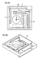
- the essentially consisting of the (can be integrated in the frame part 8) fixing element 12 together with the drive ring 1, the diagonal bar 4, the train-pressure bars 3a, 3b, 6a, 6b, 11a, 11b and, optionally, the integrated bending transducers 19a, 19b, formed Unit is referred to below as the 'drive module'.
- the drive module can be produced using injection molding technology made of polyethylene, injection-molded plastic, POM or other suitable materials.
- the frame part 8 can be an integral part of a housing (shown below in FIG. 8) or connected sufficiently rigidly thereto.
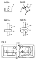
- the connection of the mechanically rigid tension-compression bars 6a, 6b to the frame part 8, the end piece 7 or to the diagonal bar 4 also takes place via solid joints. 5
- the power transmission from the drive ring 1 takes place on the shaft 39 by friction.
- load torque of such a constructed actuator to slip whereby the accuracy of the actuator is reduced.
- the slip is preferably reduced by the introduction of a positive connection between the rolling surfaces of drive ring 1 and shaft 39, in particular by a toothing is applied to the inner surface 24 of the drive ring 1 and on the outer surface 35 of the shaft 39.
- Drive ring 1 and shaft 39 preferably have a tooth difference of at least one. This means that the toothing of the inner surface 24 of the drive ring 1 comprises at least one tooth more than the outer surface 35 of the shaft 39. If drive ring 1 and shaft 39 are operated within the actuator in such a way that the toothing does not disengage, the actuator ideally operates without slip.
- the actuator provides high efficiency, high reduction, high transmittable torque based on the gearing of drive ring 1 and shaft 39, slip freedom in torque transfer, any interpolation of the rotation angle within a tooth of shaft 39 (microstep operation) ), low drive torque fluctuations (ripple) and a low tooth flank load for drive ring 1 and shaft 39, so that the wear is also reduced.
Landscapes
- General Electrical Machinery Utilizing Piezoelectricity, Electrostriction Or Magnetostriction (AREA)
Claims (16)
- Moteur électromécanique, notamment commande miniature pas à pas piézoélectrique, comportant:- deux organes électromécaniques de commande (19a, 19b) ayant des directions de travail orientées approximativement perpendiculairement l'une par rapport à l'autre,- un arbre (39) monté en rotation dans une bague de commande (1) de manière telle que la bague de commande (1) peut être sollicitée, par un déplacement des organes électromécaniques de commande (19a, 19b) dans leur direction respective de travail, pour exécuter un glissement transmis directement à l'arbre (39), si bien que l'arbre (39) pivote dans la bague de commande (1) et, de cette façon, tourne,caractérisé par le fait que- la bague de commande (1) est liée, au moyen de deux tiges de traction et compression (3a, 3b) parallèles entre elles et parallèles à l'une des deux directions de travail, lesquelles tiges comportant chacune à leurs deux extrémités une articulation (5), aux extrémités d'une tige diagonale (4), si bien que la bague de commande (1) est mobile par rapport à la tige diagonale (4) sous forme d'un cisaillement dans l'autre des deux directions de travail, et- les extrémités diamétralement opposées de la tige diagonale (4), qui est au moins partiellement en biais par rapport aux deux directions de travail, sont liées chacune à un organe de fixation (12) au moyen d'une tige de traction et compression (6a, 6b) parallèle à l'autre direction de travail et comportant à chacune de ses deux extrémités une articulation (5), l'organe de fixation (12) de l'une des tiges (6a, 6b) et le point de liaison de l'autre tige (6a, 6b) sur la tige diagonale (4) - et inversement - se faisant face approximativement le long d'une parallèle à l'une des directions de travail, si bien que la tige diagonale (4) se déplace par rapport aux organes de fixation (12) dans ladite des deux directions de travail.
- Moteur électromécanique selon la revendication 1, dans lequel les articulations (5) des tiges de traction et compression (3a, 3b, 6a, 6b) sont conçues en tant qu'articulation en corps solide.
- Moteur électromécanique selon la revendication 2, dans lequel les articulations (5) en corps solide sont formées par un amincissement de la section transversale des tiges de traction et compression (3a, 3b, 6a, 6b) sur une courte longueur.
- Moteur électromécanique selon l'une des revendications 1 à 3, dans lequel les tiges de traction et compression (3a, 3b) disposées parallèlement à l'une des directions de travail sont placées le long de deux côtés (14) ou moitiés de la bague de commande (1) se faisant face et sont liées chacune à un renforcement (13, 15) de la bague de commande (1) ménagé sur un côté opposé à la tige diagonale (4) ou sur une moitié de la bague de commande (1) opposée à la tige diagonale (4).
- Moteur électromécanique selon la revendication 4, dans lequel la longueur de la tige de traction et compression (6a) placée entre la bague de commande (1) et la tige diagonale (4) et parallèle à l'autre direction de travail est plus petite que la distance entre les deux tiges de traction et compression (3a, 3b) placées parallèlement à l'une des deux directions de travail.
- Moteur électromécanique selon l'une des revendications 1 à 5, dans lequel la tige diagonale (4) se compose d'une partie centrale disposée approximativement en parallèle à l'autre direction de travail et de parties terminales coudées par rapport à la partie centrale, les parties terminales étant coudées dans le même sens de rotation, si bien que les extrémités de la tige diagonale (4) se font approximativement réciproquement face d'une façon diamétrale.
- Moteur électromécanique selon l'une des revendications 1 à 6, dans lequel l'organe de fixation (12), qui lie la tige de traction et compression (6b) disposée parallèlement à l'autre direction de travail et se trouvant le long du coté de la tige diagonale (4) opposé à la bague de commande (1), est fixé à une partie d'un cadre (8) approximativement rectangulaire et mécaniquement rigide.
- Moteur électromécanique selon la revendication 7, dans lequel la partie de cadre (8) est conçue comme partie du boîtier de la commande pas à pas.
- Moteur électromécanique selon l'une des revendications 1 à 8, dans lequel l'organe de fixation, qui lie la tige de traction et compression (6a) disposée parallèlement à l'autre direction de travail et se trouvant le long du coté de la tige diagonale (4) tourné vers la bague de commande (1), est intégré dans un élément du fond (18) et/ou dans un couvercle (20) d'un boîtier de la commande pas à pas, où l'extrémité de la tige de traction et compression (6a) prévue pour la liaison à l'organe de fixation est dotée d'une pièce terminale (7) liée à l'organe de fixation.
- Moteur électromécanique selon l'une des revendications 1 à 9, dont les deux organes électromécaniques de commande (19a, 19b) sont des convertisseurs de flexion, de préférence des convertisseurs piézoélectriques de flexion.
- Moteur électromécanique selon la revendication 4 et 10, dans lequel, sur chacun des renforcements (13, 15) de la bague de commande (1), est liée une tige de traction et compression (11a, 11b) disposée parallèlement à l'une et, respectivement, à l'autre direction de travail et se trouvant le long d'un côté (14) ou d'une moitié de la bague de commande (1), où ladite tige de traction et compression comporte à ses deux extrémités une articulation en corps solide (5) et où, à chaque extrémité opposée au renforcement (13, 15), est couplée l'extrémité mobile d'un convertisseur de flexion (19a, 19b) placé perpendiculairement à la tige de traction et compression (11a, 11b) respective, le long d'un côté (14) ou d'une moitié de la bague de commande (1).
- Moteur électromécanique selon la revendication 10 ou 11, dans lequel au moins la partie de cadre (8), la bague de commande (1), les tiges de traction et compression (3a, 3b, 6a, 6b, 11a, 11b) et la tige diagonale (4) constituent un module de commande fabriqué en une seule pièce en moulage par injection de matière plastique, les convertisseurs de flexion (19a, 19b) étant moulés en même temps par injection dans le module de commande.
- Moteur électromécanique selon l'une des revendications 1 à 12, dans lequel il est prévu un boîtier approximativement parallélépipédique comportant un élément de fond (18) et un couvercle (20), où il est prévu, dans l'élément de fond (18), un bloc central (28) de support avec une surface d'appui (27) et un premier alésage (26) servant de palier et, dans le couvercle (20), un deuxième alésage (29) servant de palier à l'arbre (39) et où les organes de fixation (12) sont placés sur le boîtier et y sont fixés ou intégrés de manière telle que la au moins une surface cylindrique (35) de roulement de l'arbre (39) peut tourner dans une surface (24) de roulement correspondante d'un alésage annulaire (2) de la bague de commande (1).
- Moteur électromécanique selon la revendication 13, dans lequel l'arbre (39) est conçu avec une partie centrale en forme de disque dont la première surface annulaire de tranche s'applique sur le bloc support (28) et dont la surface de révolution forme la surface cylindrique de roulement (35) de l'arbre (39).
- Moteur électromécanique selon la revendication 14, dans lequel, pour protéger la fixation dans la direction z de l'axe de l'arbre (39), il est prévu un ressort en anse de panier (21) doté d'un trou (30) pour laisser passer l'arbre (39), ledit ressort en anse de panier s'appuyant, d'une part, sur la deuxième surface annulaire de tranche de la partie centrale en forme de disque de l'arbre (39) et, d'autre part, lorsque le couvercle est en place, sur une surface du couvercle de manière telle que la rotation de l'arbre (39) n'est pas gênée d'une façon sensible.
- Moteur électromécanique selon l'une des revendications 1 à 15, dans lequel, pour la transmission des forces par embrayage, un engrenage, et notamment un engrenage cycloïdal, est ménagé sur la surface intérieure (24) de l'alésage annulaire (2) de la bague de commande (1) et sur la surface de roulement (35) correspondante de l'arbre (39).
Applications Claiming Priority (2)
| Application Number | Priority Date | Filing Date | Title |
|---|---|---|---|
| DE102007023217A DE102007023217B4 (de) | 2007-05-18 | 2007-05-18 | Elektromechanischer Motor, insbesondere piezoelektrischer Mikroschrittantrieb |
| PCT/EP2008/054909 WO2008141886A1 (fr) | 2007-05-18 | 2008-04-23 | Moteur électromécanique, notamment moteur pas à pas piézoélectrique |
Publications (2)
| Publication Number | Publication Date |
|---|---|
| EP2149164A1 EP2149164A1 (fr) | 2010-02-03 |
| EP2149164B1 true EP2149164B1 (fr) | 2011-03-30 |
Family
ID=39591342
Family Applications (1)
| Application Number | Title | Priority Date | Filing Date |
|---|---|---|---|
| EP08736489A Not-in-force EP2149164B1 (fr) | 2007-05-18 | 2008-04-23 | Moteur électromécanique, notamment moteur pas à pas piézoélectrique |
Country Status (7)
| Country | Link |
|---|---|
| US (1) | US8004149B2 (fr) |
| EP (1) | EP2149164B1 (fr) |
| JP (1) | JP5130356B2 (fr) |
| CN (1) | CN101681987B (fr) |
| AT (1) | ATE504089T1 (fr) |
| DE (2) | DE102007023217B4 (fr) |
| WO (1) | WO2008141886A1 (fr) |
Families Citing this family (8)
| Publication number | Priority date | Publication date | Assignee | Title |
|---|---|---|---|---|
| DE102007023200B4 (de) * | 2007-05-18 | 2011-07-28 | Continental Automotive GmbH, 30165 | Elektromechanischer Motor, insbesondere piezoelektrischer Mikroschrittantrieb |
| DE102007023199B4 (de) * | 2007-05-18 | 2011-07-28 | Continental Automotive GmbH, 30165 | Elektromechanischer Motor, inbesondere piezoelektrischer Mikroschrittantrieb |
| DE102007023201A1 (de) * | 2007-05-18 | 2008-11-20 | Continental Automotive Gmbh | Elektromechanischer Motor, insbesondere piezoelektrischer Mikroschrittantrieb |
| WO2010051797A2 (fr) * | 2008-11-10 | 2010-05-14 | Richter, Berta | Entraînement universel électrique de piézomoteur |
| JP4985747B2 (ja) * | 2009-11-12 | 2012-07-25 | カシオ計算機株式会社 | 駆動装置 |
| JP5835212B2 (ja) * | 2010-03-31 | 2015-12-24 | 株式会社ニコン | モータ装置、モータ装置の製造方法及びロボット装置 |
| US8358048B2 (en) * | 2010-11-17 | 2013-01-22 | J. G. Smits | High speed optical scanning mirror system using piezoelectric benders |
| EP4391349B1 (fr) * | 2022-12-23 | 2025-10-01 | The Swatch Group Research and Development Ltd | Moteur piézoélectrique rotatif résistant aux chocs, notamment pour l'horlogerie |
Family Cites Families (10)
| Publication number | Priority date | Publication date | Assignee | Title |
|---|---|---|---|---|
| JPS62152381A (ja) * | 1985-12-25 | 1987-07-07 | Canon Inc | 回転動力装置 |
| JPS62293978A (ja) * | 1986-06-11 | 1987-12-21 | Canon Inc | 回転アクチエ−タ |
| DE3721682A1 (de) * | 1986-10-13 | 1988-04-21 | Pav Praezisions Apparatebau Ag | Bewegungselement fuer feinmess- oder justiergeraete |
| US4928030A (en) * | 1988-09-30 | 1990-05-22 | Rockwell International Corporation | Piezoelectric actuator |
| US5079471A (en) * | 1990-06-04 | 1992-01-07 | Martin Marietta Corporation | High torque harmonic traction motor |
| US5705878A (en) * | 1995-11-29 | 1998-01-06 | Lewis; Aaron | Flat scanning stage for scanned probe microscopy |
| DE10010392B4 (de) * | 1999-03-08 | 2005-03-17 | Technische Universität Ilmenau Abteilung Forschungsförderung und Technologietransfer | Piezoelekronisches X-Y-Mikropositioniersystem |
| DE19952946A1 (de) | 1999-11-03 | 2001-05-17 | Siemens Ag | Elektromechanischer Motor |
| US6876129B2 (en) * | 2001-09-26 | 2005-04-05 | Mitsuba Corporation | Rotary actuator and method of controlling an actuator |
| DE10322836A1 (de) * | 2003-05-19 | 2004-12-23 | Siemens Ag | Inkrementeller Antrieb |
-
2007
- 2007-05-18 DE DE102007023217A patent/DE102007023217B4/de not_active Expired - Fee Related
-
2008
- 2008-04-23 AT AT08736489T patent/ATE504089T1/de active
- 2008-04-23 JP JP2010508770A patent/JP5130356B2/ja not_active Expired - Fee Related
- 2008-04-23 EP EP08736489A patent/EP2149164B1/fr not_active Not-in-force
- 2008-04-23 US US12/600,787 patent/US8004149B2/en not_active Expired - Fee Related
- 2008-04-23 CN CN2008800165204A patent/CN101681987B/zh not_active Expired - Fee Related
- 2008-04-23 WO PCT/EP2008/054909 patent/WO2008141886A1/fr not_active Ceased
- 2008-04-23 DE DE502008003013T patent/DE502008003013D1/de active Active
Also Published As
| Publication number | Publication date |
|---|---|
| DE102007023217A1 (de) | 2008-11-20 |
| US20100295418A1 (en) | 2010-11-25 |
| WO2008141886A1 (fr) | 2008-11-27 |
| ATE504089T1 (de) | 2011-04-15 |
| JP5130356B2 (ja) | 2013-01-30 |
| DE502008003013D1 (de) | 2011-05-12 |
| JP2010527576A (ja) | 2010-08-12 |
| EP2149164A1 (fr) | 2010-02-03 |
| US8004149B2 (en) | 2011-08-23 |
| CN101681987A (zh) | 2010-03-24 |
| CN101681987B (zh) | 2013-10-16 |
| DE102007023217B4 (de) | 2011-07-21 |
Similar Documents
| Publication | Publication Date | Title |
|---|---|---|
| EP2158621B1 (fr) | Moteur électromécanique, notamment moteur pas à pas piézoélectrique | |
| EP2160774B1 (fr) | Moteur électromécanique, notamment moteur pas à pas piézoélectrique | |
| EP2149164B1 (fr) | Moteur électromécanique, notamment moteur pas à pas piézoélectrique | |
| EP1098429B1 (fr) | Moteur électromécanique | |
| EP2759052B1 (fr) | Actionneur rotatif | |
| EP2064754A1 (fr) | Entrainement electromagnetique de reglage | |
| EP2158622B1 (fr) | Moteur électromécanique, notamment moteur pas à pas piézoélectrique | |
| DE10237881B4 (de) | Mikromanipulator | |
| DE10010392A1 (de) | Piezoelekronisches X-Y-Mikropositioniersystem | |
| EP2277210B1 (fr) | Mécanisme d'entraînement en rotation | |
| DE112009005360T5 (de) | Bestimmung einer normalkraft für einen elektromechanischen motor | |
| WO2007144275A1 (fr) | Dispositif d'entraînement d'actionneur de corps fixe ou procédé pour entraîner un dispositif d'entraînement d'actionneur de corps fixe | |
| EP2027613B1 (fr) | Dispositif d'entraînement d'actionneur de corps à l'etat solide ou procédé pour entraîner un dispositif d'entraînement d'actionneur de corps à l'etat solide | |
| EP1403104A2 (fr) | Barre stabilisatrice réglable pour suspension | |
| EP2130237B1 (fr) | Système de positionnement pour table micro-ajustée | |
| EP2568189B1 (fr) | Accouplement d'arbre | |
| DE102007053475B4 (de) | Positioniersystem | |
| EP2143153B1 (fr) | Entraînement à actionneurs à l'état solide, notamment entraînement piézoélectrique, et procédé pour obtenir des données de détection d'un entraînement à actionneurs à l'état solide, notamment d'un entraînement piézoélectrique | |
| DE29704679U1 (de) | Piezoelektrischer Bewegungswandler | |
| DE102006027406A1 (de) | Festkörperaktor-Antriebsvorrichtung |
Legal Events
| Date | Code | Title | Description |
|---|---|---|---|
| PUAI | Public reference made under article 153(3) epc to a published international application that has entered the european phase |
Free format text: ORIGINAL CODE: 0009012 |
|
| 17P | Request for examination filed |
Effective date: 20091218 |
|
| AK | Designated contracting states |
Kind code of ref document: A1 Designated state(s): AT BE BG CH CY CZ DE DK EE ES FI FR GB GR HR HU IE IS IT LI LT LU LV MC MT NL NO PL PT RO SE SI SK TR |
|
| AX | Request for extension of the european patent |
Extension state: AL BA MK RS |
|
| DAX | Request for extension of the european patent (deleted) | ||
| GRAP | Despatch of communication of intention to grant a patent |
Free format text: ORIGINAL CODE: EPIDOSNIGR1 |
|
| RIC1 | Information provided on ipc code assigned before grant |
Ipc: H01L 41/09 20060101AFI20100823BHEP |
|
| GRAS | Grant fee paid |
Free format text: ORIGINAL CODE: EPIDOSNIGR3 |
|
| GRAA | (expected) grant |
Free format text: ORIGINAL CODE: 0009210 |
|
| AK | Designated contracting states |
Kind code of ref document: B1 Designated state(s): AT BE BG CH CY CZ DE DK EE ES FI FR GB GR HR HU IE IS IT LI LT LU LV MC MT NL NO PL PT RO SE SI SK TR |
|
| REG | Reference to a national code |
Ref country code: GB Ref legal event code: FG4D Free format text: NOT ENGLISH |
|
| REG | Reference to a national code |
Ref country code: CH Ref legal event code: EP |
|
| REG | Reference to a national code |
Ref country code: IE Ref legal event code: FG4D |
|
| REF | Corresponds to: |
Ref document number: 502008003013 Country of ref document: DE Date of ref document: 20110512 Kind code of ref document: P |
|
| REG | Reference to a national code |
Ref country code: DE Ref legal event code: R096 Ref document number: 502008003013 Country of ref document: DE Effective date: 20110512 |
|
| REG | Reference to a national code |
Ref country code: NL Ref legal event code: VDEP Effective date: 20110330 |
|
| PG25 | Lapsed in a contracting state [announced via postgrant information from national office to epo] |
Ref country code: LT Free format text: LAPSE BECAUSE OF FAILURE TO SUBMIT A TRANSLATION OF THE DESCRIPTION OR TO PAY THE FEE WITHIN THE PRESCRIBED TIME-LIMIT Effective date: 20110330 Ref country code: SE Free format text: LAPSE BECAUSE OF FAILURE TO SUBMIT A TRANSLATION OF THE DESCRIPTION OR TO PAY THE FEE WITHIN THE PRESCRIBED TIME-LIMIT Effective date: 20110330 Ref country code: LV Free format text: LAPSE BECAUSE OF FAILURE TO SUBMIT A TRANSLATION OF THE DESCRIPTION OR TO PAY THE FEE WITHIN THE PRESCRIBED TIME-LIMIT Effective date: 20110330 Ref country code: HR Free format text: LAPSE BECAUSE OF FAILURE TO SUBMIT A TRANSLATION OF THE DESCRIPTION OR TO PAY THE FEE WITHIN THE PRESCRIBED TIME-LIMIT Effective date: 20110330 Ref country code: GR Free format text: LAPSE BECAUSE OF FAILURE TO SUBMIT A TRANSLATION OF THE DESCRIPTION OR TO PAY THE FEE WITHIN THE PRESCRIBED TIME-LIMIT Effective date: 20110701 |
|
| LTIE | Lt: invalidation of european patent or patent extension |
Effective date: 20110330 |
|
| PG25 | Lapsed in a contracting state [announced via postgrant information from national office to epo] |
Ref country code: CY Free format text: LAPSE BECAUSE OF FAILURE TO SUBMIT A TRANSLATION OF THE DESCRIPTION OR TO PAY THE FEE WITHIN THE PRESCRIBED TIME-LIMIT Effective date: 20110330 Ref country code: SI Free format text: LAPSE BECAUSE OF FAILURE TO SUBMIT A TRANSLATION OF THE DESCRIPTION OR TO PAY THE FEE WITHIN THE PRESCRIBED TIME-LIMIT Effective date: 20110330 Ref country code: NO Free format text: LAPSE BECAUSE OF FAILURE TO SUBMIT A TRANSLATION OF THE DESCRIPTION OR TO PAY THE FEE WITHIN THE PRESCRIBED TIME-LIMIT Effective date: 20110630 Ref country code: FI Free format text: LAPSE BECAUSE OF FAILURE TO SUBMIT A TRANSLATION OF THE DESCRIPTION OR TO PAY THE FEE WITHIN THE PRESCRIBED TIME-LIMIT Effective date: 20110330 |
|
| REG | Reference to a national code |
Ref country code: IE Ref legal event code: FD4D |
|
| BERE | Be: lapsed |
Owner name: CONTINENTAL AUTOMOTIVE G.M.B.H. Effective date: 20110430 |
|
| PG25 | Lapsed in a contracting state [announced via postgrant information from national office to epo] |
Ref country code: EE Free format text: LAPSE BECAUSE OF FAILURE TO SUBMIT A TRANSLATION OF THE DESCRIPTION OR TO PAY THE FEE WITHIN THE PRESCRIBED TIME-LIMIT Effective date: 20110330 Ref country code: PT Free format text: LAPSE BECAUSE OF FAILURE TO SUBMIT A TRANSLATION OF THE DESCRIPTION OR TO PAY THE FEE WITHIN THE PRESCRIBED TIME-LIMIT Effective date: 20110801 |
|
| PG25 | Lapsed in a contracting state [announced via postgrant information from national office to epo] |
Ref country code: CZ Free format text: LAPSE BECAUSE OF FAILURE TO SUBMIT A TRANSLATION OF THE DESCRIPTION OR TO PAY THE FEE WITHIN THE PRESCRIBED TIME-LIMIT Effective date: 20110330 Ref country code: RO Free format text: LAPSE BECAUSE OF FAILURE TO SUBMIT A TRANSLATION OF THE DESCRIPTION OR TO PAY THE FEE WITHIN THE PRESCRIBED TIME-LIMIT Effective date: 20110330 Ref country code: MC Free format text: LAPSE BECAUSE OF NON-PAYMENT OF DUE FEES Effective date: 20110430 Ref country code: SK Free format text: LAPSE BECAUSE OF FAILURE TO SUBMIT A TRANSLATION OF THE DESCRIPTION OR TO PAY THE FEE WITHIN THE PRESCRIBED TIME-LIMIT Effective date: 20110330 Ref country code: IS Free format text: LAPSE BECAUSE OF FAILURE TO SUBMIT A TRANSLATION OF THE DESCRIPTION OR TO PAY THE FEE WITHIN THE PRESCRIBED TIME-LIMIT Effective date: 20110730 Ref country code: ES Free format text: LAPSE BECAUSE OF FAILURE TO SUBMIT A TRANSLATION OF THE DESCRIPTION OR TO PAY THE FEE WITHIN THE PRESCRIBED TIME-LIMIT Effective date: 20110711 |
|
| PG25 | Lapsed in a contracting state [announced via postgrant information from national office to epo] |
Ref country code: NL Free format text: LAPSE BECAUSE OF FAILURE TO SUBMIT A TRANSLATION OF THE DESCRIPTION OR TO PAY THE FEE WITHIN THE PRESCRIBED TIME-LIMIT Effective date: 20110330 Ref country code: MT Free format text: LAPSE BECAUSE OF FAILURE TO SUBMIT A TRANSLATION OF THE DESCRIPTION OR TO PAY THE FEE WITHIN THE PRESCRIBED TIME-LIMIT Effective date: 20110330 |
|
| PG25 | Lapsed in a contracting state [announced via postgrant information from national office to epo] |
Ref country code: DE Free format text: LAPSE BECAUSE OF NON-PAYMENT OF DUE FEES Effective date: 20111101 Ref country code: BE Free format text: LAPSE BECAUSE OF NON-PAYMENT OF DUE FEES Effective date: 20110430 Ref country code: IE Free format text: LAPSE BECAUSE OF FAILURE TO SUBMIT A TRANSLATION OF THE DESCRIPTION OR TO PAY THE FEE WITHIN THE PRESCRIBED TIME-LIMIT Effective date: 20110330 |
|
| PLBE | No opposition filed within time limit |
Free format text: ORIGINAL CODE: 0009261 |
|
| STAA | Information on the status of an ep patent application or granted ep patent |
Free format text: STATUS: NO OPPOSITION FILED WITHIN TIME LIMIT |
|
| PG25 | Lapsed in a contracting state [announced via postgrant information from national office to epo] |
Ref country code: PL Free format text: LAPSE BECAUSE OF FAILURE TO SUBMIT A TRANSLATION OF THE DESCRIPTION OR TO PAY THE FEE WITHIN THE PRESCRIBED TIME-LIMIT Effective date: 20110330 Ref country code: DK Free format text: LAPSE BECAUSE OF FAILURE TO SUBMIT A TRANSLATION OF THE DESCRIPTION OR TO PAY THE FEE WITHIN THE PRESCRIBED TIME-LIMIT Effective date: 20110330 |
|
| 26N | No opposition filed |
Effective date: 20120102 |
|
| REG | Reference to a national code |
Ref country code: DE Ref legal event code: R119 Ref document number: 502008003013 Country of ref document: DE Effective date: 20111101 |
|
| PG25 | Lapsed in a contracting state [announced via postgrant information from national office to epo] |
Ref country code: IT Free format text: LAPSE BECAUSE OF FAILURE TO SUBMIT A TRANSLATION OF THE DESCRIPTION OR TO PAY THE FEE WITHIN THE PRESCRIBED TIME-LIMIT Effective date: 20110330 |
|
| REG | Reference to a national code |
Ref country code: CH Ref legal event code: PL |
|
| GBPC | Gb: european patent ceased through non-payment of renewal fee |
Effective date: 20120423 |
|
| PG25 | Lapsed in a contracting state [announced via postgrant information from national office to epo] |
Ref country code: CH Free format text: LAPSE BECAUSE OF NON-PAYMENT OF DUE FEES Effective date: 20120430 Ref country code: GB Free format text: LAPSE BECAUSE OF NON-PAYMENT OF DUE FEES Effective date: 20120423 Ref country code: LI Free format text: LAPSE BECAUSE OF NON-PAYMENT OF DUE FEES Effective date: 20120430 |
|
| PG25 | Lapsed in a contracting state [announced via postgrant information from national office to epo] |
Ref country code: LU Free format text: LAPSE BECAUSE OF NON-PAYMENT OF DUE FEES Effective date: 20110423 |
|
| PG25 | Lapsed in a contracting state [announced via postgrant information from national office to epo] |
Ref country code: BG Free format text: LAPSE BECAUSE OF FAILURE TO SUBMIT A TRANSLATION OF THE DESCRIPTION OR TO PAY THE FEE WITHIN THE PRESCRIBED TIME-LIMIT Effective date: 20110630 |
|
| PG25 | Lapsed in a contracting state [announced via postgrant information from national office to epo] |
Ref country code: TR Free format text: LAPSE BECAUSE OF FAILURE TO SUBMIT A TRANSLATION OF THE DESCRIPTION OR TO PAY THE FEE WITHIN THE PRESCRIBED TIME-LIMIT Effective date: 20110330 |
|
| PG25 | Lapsed in a contracting state [announced via postgrant information from national office to epo] |
Ref country code: HU Free format text: LAPSE BECAUSE OF FAILURE TO SUBMIT A TRANSLATION OF THE DESCRIPTION OR TO PAY THE FEE WITHIN THE PRESCRIBED TIME-LIMIT Effective date: 20110330 |
|
| REG | Reference to a national code |
Ref country code: AT Ref legal event code: MM01 Ref document number: 504089 Country of ref document: AT Kind code of ref document: T Effective date: 20130423 |
|
| PG25 | Lapsed in a contracting state [announced via postgrant information from national office to epo] |
Ref country code: AT Free format text: LAPSE BECAUSE OF NON-PAYMENT OF DUE FEES Effective date: 20130423 |
|
| REG | Reference to a national code |
Ref country code: FR Ref legal event code: PLFP Year of fee payment: 9 |
|
| REG | Reference to a national code |
Ref country code: FR Ref legal event code: PLFP Year of fee payment: 10 |
|
| REG | Reference to a national code |
Ref country code: FR Ref legal event code: PLFP Year of fee payment: 11 |
|
| PGFP | Annual fee paid to national office [announced via postgrant information from national office to epo] |
Ref country code: FR Payment date: 20190424 Year of fee payment: 12 |
|
| PG25 | Lapsed in a contracting state [announced via postgrant information from national office to epo] |
Ref country code: FR Free format text: LAPSE BECAUSE OF NON-PAYMENT OF DUE FEES Effective date: 20200430 |