EP2149244B1 - Verfahren und system zum herstellen eines anrufs über ein ip-multimedia-kommunikationssystem und leitungsvermitteltes kommunikationssystem - Google Patents
Verfahren und system zum herstellen eines anrufs über ein ip-multimedia-kommunikationssystem und leitungsvermitteltes kommunikationssystem Download PDFInfo
- Publication number
- EP2149244B1 EP2149244B1 EP07747293A EP07747293A EP2149244B1 EP 2149244 B1 EP2149244 B1 EP 2149244B1 EP 07747293 A EP07747293 A EP 07747293A EP 07747293 A EP07747293 A EP 07747293A EP 2149244 B1 EP2149244 B1 EP 2149244B1
- Authority
- EP
- European Patent Office
- Prior art keywords
- user terminal
- address
- signaling
- network
- ims
- Prior art date
- Legal status (The legal status is an assumption and is not a legal conclusion. Google has not performed a legal analysis and makes no representation as to the accuracy of the status listed.)
- Not-in-force
Links
- 238000000034 method Methods 0.000 title claims abstract description 53
- 238000004891 communication Methods 0.000 title description 27
- 230000011664 signaling Effects 0.000 claims abstract description 176
- 230000000977 initiatory effect Effects 0.000 claims description 43
- 238000010295 mobile communication Methods 0.000 description 8
- 230000005540 biological transmission Effects 0.000 description 3
- 230000000694 effects Effects 0.000 description 3
- 238000010586 diagram Methods 0.000 description 2
- 238000005516 engineering process Methods 0.000 description 2
- 230000007246 mechanism Effects 0.000 description 2
- 102000018059 CS domains Human genes 0.000 description 1
- 108050007176 CS domains Proteins 0.000 description 1
- 241001481828 Glyptocephalus cynoglossus Species 0.000 description 1
- 238000006243 chemical reaction Methods 0.000 description 1
- 230000009977 dual effect Effects 0.000 description 1
Images



Classifications
-
- H—ELECTRICITY
- H04—ELECTRIC COMMUNICATION TECHNIQUE
- H04L—TRANSMISSION OF DIGITAL INFORMATION, e.g. TELEGRAPHIC COMMUNICATION
- H04L65/00—Network arrangements, protocols or services for supporting real-time applications in data packet communication
- H04L65/10—Architectures or entities
- H04L65/102—Gateways
- H04L65/1033—Signalling gateways
- H04L65/104—Signalling gateways in the network
-
- H—ELECTRICITY
- H04—ELECTRIC COMMUNICATION TECHNIQUE
- H04W—WIRELESS COMMUNICATION NETWORKS
- H04W76/00—Connection management
- H04W76/10—Connection setup
- H04W76/15—Setup of multiple wireless link connections
-
- H—ELECTRICITY
- H04—ELECTRIC COMMUNICATION TECHNIQUE
- H04L—TRANSMISSION OF DIGITAL INFORMATION, e.g. TELEGRAPHIC COMMUNICATION
- H04L65/00—Network arrangements, protocols or services for supporting real-time applications in data packet communication
- H04L65/10—Architectures or entities
- H04L65/1016—IP multimedia subsystem [IMS]
-
- H—ELECTRICITY
- H04—ELECTRIC COMMUNICATION TECHNIQUE
- H04L—TRANSMISSION OF DIGITAL INFORMATION, e.g. TELEGRAPHIC COMMUNICATION
- H04L65/00—Network arrangements, protocols or services for supporting real-time applications in data packet communication
- H04L65/1066—Session management
- H04L65/1069—Session establishment or de-establishment
-
- H—ELECTRICITY
- H04—ELECTRIC COMMUNICATION TECHNIQUE
- H04W—WIRELESS COMMUNICATION NETWORKS
- H04W80/00—Wireless network protocols or protocol adaptations to wireless operation
- H04W80/08—Upper layer protocols
- H04W80/10—Upper layer protocols adapted for application session management, e.g. SIP [Session Initiation Protocol]
Definitions
- the present invention relates to communications systems and, more particularly, to data transfer between user terminals involving an IP Multi media communications System (IMS) and a Circuit Switched (CS) communications system, such as mobile CS communications system.
- IMS IP Multi media communications System
- CS Circuit Switched
- IMS IP Multi media System
- CS Circuit Switched
- IMS IP Multi media System
- the call establishment may, for example, be enriched with multi media alerting information or caller information.
- IMS may be used for establishing speech calls (voice session), but also for non-call related activities, such as establishing a chat session or for transferring a file or the like.
- the Universal Mobile Telephony System may be suitable for IMS based voice sessions.
- High Speed Downlink Packet Access (HSDPA) and High Speed Uplink Packet Access (HSUPA), jointly referred to as High Speed Packet Access (HSPA)
- HSPA High Speed Packet Access
- the current mobile communications networks like the Global System for Mobile communications (GSM) and UMTS Radio Access Networks (RAN) networks do, however, have sufficient capacity for offering CS based speech connection to a large number of users.
- GSM Global System for Mobile communications
- RAN Radio Access Networks
- WLAN Wireless Local Area Network
- WiMAX Worldwide interoperability for Microwave Access
- Combinational Services Mechanisms to combine IMS and CS, to offer enriched call experience, are known as Combinational Services. Details of Combinational Services are specified in, amongst others, the Technical Specification of the 3rd Generation Partnership Project (3GPP), 3GPP TS 23.279. Combinational Services are also known as "combination of CS and IMS services" (CSI).
- 3GPP Technical Specification of the 3rd Generation Partnership Project
- 3GPP TS 23.279 3rd Generation Partnership Project
- Combinational Services are also known as "combination of CS and IMS services" (CSI).
- IMS MMO IMS Multi Media Office
- 3GPP has drafted various network CSI scenarios, known as Alpha, Beta and Gamma.
- the Alpha solution entails that a CS call is combined with a PS-based media session.
- the CS call is used for the speech connection between the calling and called party.
- the PS session is used for multimedia transfer.
- the user terminals of the calling and called party correlate the speech connection and the media session and combine these into an enriched call.
- the Alpha solution is standardised in 3GPP as Combinational Services.
- Quintessential to the Alpha solution is that the voice call between the calling and called party is CS end-to-end.
- the calling party uses the Mobile Subscriber (MS) Integrated Services Digital Network (ISDN) Number (MSISDN) of the called party to set up the call.
- MS Mobile Subscriber
- ISDN Integrated Services Digital Network
- MSISDN Mobile Subscriber Network Number
- the IMS signalling between the calling and the called party runs independently of the CS call signalling between the calling and the called party.
- the Beta solution entails that a user has a Session Initiation Protocol (SIP) capable terminal.
- SIP Session Initiation Protocol
- the SIP User Agent uses SIP signalling for call establishment.
- a control node in the IMS network establishes a CS call towards the calling party; the CS call is also connected to a MediaGateWay (MGW), for connection to the called party for this call.
- MGW MediaGateWay
- Beta solution Inherent complexity of the Beta solution is that the establishment of the voice call is done under control of the IMS server (i.e. SIP Application Servers) (i.e. the "Beta server"). This makes the architecture more complex.
- the SIP-AS has to control two SIP Sessions for a multimedia voice call establishment:
- the Beta server then also establishes an additional SIP session towards the called party.
- This SIP session will also be converted to ISUP and DTAP, so it can be offered to the called party.
- the voice connection towards the called party will run from the MGW. Hence, voice between calling and called party is established through a centralised MGW.
- the Beta server has to take additional steps to establish the speech path between the calling and the called party. This implies, amongst others, that the Beta server needs to have the MSISDNs of the calling and called party.
- the establishment of the CS call to the mobile calling and called party entails also ISUP routing through a Gateway Mobile Switching Centre (GMSC) and the Mobile Switching Centre (MSC), Home Location Register (HLR) interrogation etc.
- GMSC Gateway Mobile Switching Centre
- MSC Mobile Switching Centre
- HLR Home Location Register
- a possible terminating call Intelligent Network (IN) service for the calling or called party needs to be suppressed for this call. This makes Beta a complex solution.
- the Gamma solution entails that a GSM terminal is connected to the GSM network as per current methodology.
- standard CS signalling is used, i.e. the terminal uses DTAP signaling towards the serving MSC.
- the MSC will convert the DTAP signalling to the SIP signalling.
- the MSC has built-in Media Gateway Control Function (MGCF), enabling the MSC to route the call immediately to the IMS network.
- MGCF Media Gateway Control Function
- the MSC emulates an IMS User Agent, on behalf of the GSM user. When the user establishes a call, this call will be offered to the IMS network as originating IMS call.
- Quintessential to the gamma solution is that the call establishment from the terminal is CS.
- the calling party uses the MSISDN of the called party to establish the call.
- a voice connection, for example, between calling and called party is established through CS signaling form the terminals.
- SIP signaling may be present in the Gamma solution this is, however, not related to the establishment of the voice call.
- SIP signaling may be used for the transfer of multimedia components between the calling and called party.
- GB-A-2 410 855 discloses a communications system for establishing a communication between two terminals, involving a Packed Switched, PS, as well as circuit Switched, CS, connection.
- D1 teaches to modify the IMS network by introducing a SIP router and a SIP Application Server for intercepting and altering messages to be exchanged between the user terminals.
- US 2005/195762 A1 discloses a solution for establishing a communication in a mobile communication system, wherein the data stream is carried by at least two types of domain (e.g. PS and CS domains).
- the IMS network is modified by introducing a Media GateWay, MGW, or other server capable of and used for setting up a CS communication.
- US 2007/053343 A1 discloses a method of setting up a call between two nodes of a communications system, wherein the call extends between at least one CS network and a PS network.
- the IMS network is provided with a Serving Call State Control function Node (S-CSCF), which intercepts and modifies messages between the two nodes of a communications system, "knowing" that at least one of them uses a CS network.
- S-CSCF Serving Call State Control function Node
- the present invention provides a method of data transfer between a first user terminal, arranged for supporting connections in a first Circuit Switched, CS, network and for simultaneously supporting internet protocol Multi media System, IMS, signaling and CS signaling, and a second user terminal, arranged for supporting sessions and IMS signaling in an IMS, wherein the first CS network comprises a first internet Protocol, IP, access converter arranged for supporting data transfer in the first CS network and in an IP network, such as disclosed by GB-A-2 410 855 , wherein the invention is characterized in that the method comprises the steps of:
- IMS IP Multi media communications System
- CS Circuit Switched
- the present invention provides a method of establishing a call between a calling user terminal arranged for supporting sessions and signaling in an IMS, and a called user terminal arranged for supporting connections in a CS network and arranged for simultaneously supporting IMS signaling and CS signaling, the method being characterized by the steps of:
- the usage of the CS connection for carrying the data to be transferred is completely under the control of and transparent to the user terminal which makes use of the CS connection, i.e. the called user terminal.
- the IMS network also called the IMS core network, may invoke IMS service(s) as per normal, without having to take care of establishing the CS connection.
- IMS signalling is used for initiating and establishing the call between the calling and the called party. Because call initiation and call establishment follows IMS principles, call enrichments are included and need not separately provided for. Initiation and establishment of the connection in the CS network is performed in accordance with existing CS methodology.
- the present invention provides a method of establishing a call between a calling user terminal arranged for supporting connections in a Circuit Switched, CS, network and arranged for simultaneously supporting IMS signalling and CS signalling, and a called user terminal arranged for supporting sessions and signalling in an IP Multi media System, IMS, the method being characterized by the steps of:
- the usage of the CS connection for carrying the data to be transferred is also completely under the control of and transparent to the user terminal which makes use of the CS connection, i.e. the calling user terminal.
- the IMS core network may invoke IMS service(s) as per normal, including call enrichments, without having to take care of establishing the CS connection.
- the present invention provides a method of establishing a call between a calling user terminal arranged for supporting connections in a Circuit Switched, CS, network and arranged for simultaneously supporting IMS signaling and CS signaling, and a called user terminal arranged for supporting sessions and signaling in an IP Multi media System, IMS, the method being characterized by the steps of:
- call initiation by the calling terminal is started in the IMS, by IMS signaling of the calling user terminal to the called user terminal.
- a CS connection towards the IP Access Converter is only initiated by the calling terminal if the called terminal accepts the call initiation by providing the first IP address to the calling terminal.
- usage of the CS connections for carrying the data to be transferred is completely under the control of and transparent to the calling user terminal, and that the IMS core network may invoke IMS service(s) as per normal, including call enrichments, without having to take care of establishing the CS connection.
- the present invention provides a method of establishing a call between a calling user terminal arranged for supporting connections in a first Circuit Switched, CS, network and arranged for simultaneously supporting IMS signaling and CS signaling, and a called user terminal arranged for supporting connections in a second Circuit Switched, CS, network and arranged for simultaneously supporting IMS signaling and CS signaling, the method being characterized by the steps of:
- Both the calling and the called user terminal make use of a CS connection for transferring data.
- the calling and called user terminal do not connect by a CS call end-to-end.
- Data transfer is partly established over an IP network between the first and second IP Access Converter, which IP network according to the invention may be the public IP network such as the internet, a private IP network or an IMS, for example.
- IP network may be the public IP network such as the internet, a private IP network or an IMS, for example.
- the first and second CS networks may form part of the same network or networks operated by the same telecommunication operator, for example.
- the usage of the CS connections for carrying the data to be transferred is again also completely under the control of and transparent to the user terminals, and that the IMS core network may invoke IMS service(s) as per normal, including call enrichments, without having to take care of establishing the CS connection.
- the call is established by starting with CS signalling first.
- the calling user terminal first reserves a CS connection for data transport.
- an IP address for data transfer is already available and can be signalled towards the called user terminal.
- the present invention provides a method of establishing a call between a calling user terminal arranged for supporting connections in a first Circuit Switched, CS, network and arranged for simultaneously supporting IMS signaling and CS signaling, and a called user terminal arranged for supporting connections in a second Circuit Switched, CS, network and arranged for simultaneously supporting IMS signaling and CS signaling, the method being characterized by the steps of:
- the calling party starts with IMS signalling.
- the further steps for establishing the required connections and IP addresses are performed. Rationale of this method is, like in the third aspect of the invention, that a CS connection to an IP Access Converter is only established if the called party accepts the call.
- the usage of the CS connections for carrying the data to be transferred is again also completely under the control of and transparent to the user terminals, and that the IMS core network may invoke IMS service(s) as per normal, including call enrichments, without having to take care of establishing the CS connection.
- a CS connection towards an IP Access Converter is established by providing a further IP address to the IP access converter by the MGW, the further IP address being associated with the CS connection for data transfer by the IP Access Converter with the user terminal.
- the IP Access Converter associates the further IP address and the respective first and second IP address, whichever is applicable, with the further IP address to effect data transfer.
- the further IP address may be provided to the IP Access Converter by an intermediate network node in the CS network, such as a Mobile Switching Center (MSC) if the CS network is a mobile CS communications network such as, but not limited to, a mobile communications arranged for operation in accordance with a Global System for Mobile communications (GSM).
- MSC Mobile Switching Center
- GSM Global System for Mobile communications
- the data transfer, or media data transfer or payload may be any type of data.
- the method according to the invention is particularly suitable for the transfer of real time data, including speech data, audio data, video data, fax data, etc..
- a user terminal arranged for establishing a CS connection comprises an IMS client and a CS call client which are operatively connected, and wherein Session initiation Protocol, SIP, signalling is used by the IMS client for initiating and/or establishing a call, and wherein the CS call client initiates a CS connection.
- Session initiation Protocol SIP
- the invention further provides a communications system for supporting the method of the invention in any or all of the aspects elucidated above.
- the invention also provides a user terminal arranged for operating in accordance with the method of the invention in any or all aspects thereof.
- the user terminal is arranged for supporting connections in a Circuit Switched, CS, network and for simultaneously supporting Internet protocol Multi media System, IMS, signaling and CS signaling, the user terminal comprising an Internet protocol Multi media System, IMS, client and a CS client which are operatively connected, wherein the IMS client is arranged for supporting IMS signaling and the CS client is arranged for supporting CS signaling, characterized in that the IMS client is arranged for receiving a first Internet Protocol, IP, address from another user terminal through end-to-end IMS signaling and the CS client is arranged for transferring the first IP address to an IP access converter comprised by the CS network using CS signaling, and wherein the CS client is arranged for receiving a second IP address from the IP access converter through CS signaling and the IMS client is arranged for transferring the second IP address to the another user terminal using end-to-end IMS signaling, in order to transfer data between the user terminals using the first IP address and the second IP address.
- IP Internet Protocol
- the invention further comprises an IP Access Converter, arranged for operating in accordance with the method of the invention in any or all aspects thereof.
- the IP Access Converter may be operatively arranged in and supported by at least one network node of a communications network.
- the IP access converter is arranged for supporting data transfer in a first Circuit Switched, CS, network and in an IP network for data transfer between a first user terminal, arranged for supporting connections in the first CS network and for simultaneously supporting Internet protocol Multi media System, IMS, signaling and CS signaling, and a second user terminal, arranged for supporting sessions and IMS signaling in an IMS, and characterized in that the IP access converter is arranged for:
- the invention further relates to a network node, such as an MSC, arranged for operating in accordance with the method of the invention in any or all aspects thereof.
- a network node such as an MSC
- the present invention will be illustrated by way of example and not by way of limitation by embodiments wherein a call is established in an IP Multi media communications System (IMS) and a mobile Circuit Switched (CS) communications system operating in accordance with the Global System for Mobile Communication (GSM).
- IMS IP Multi media communications System
- CS Circuit Switched
- GSM Global System for Mobile Communication
- Figure 1 is a simplified schematic view of part of a GSM communications system and an IMS for illustrating end-to-end data transfer in accordance with the principles of the present invention.
- the GSM mobile user terminal or User Equipment 1 is capable of supporting connections in a Circuit Switched, CS, network and arranged for simultaneously supporting IMS signaling and CS signaling.
- the signaling operations of user terminal 1 are supported by a so-called IMS client 2 and a so-called CS client 3, operating in accordance with standardized IMS signaling and CS signaling protocols, respectively.
- the IMS client 2 and the CS client 3 are operatively connected as indicated by a double arrow 4.
- SIP Session Initiation Protocol
- IMS signaling provides for call enrichments at call initiation and call establishment following IMS principles.
- the GSM terminal 1 is GSM attached at a GSM access and GSM core 5, such as a Mobile Switching Centre (MSC).
- GSM terminal 5 is attached via a General Packet Radio Service (GPRS), GPRS access, GPRS core, IMS core 6 for the establishment of a Packet Data Protocol Context (PDP Context, PDPc) and for IMS registration.
- GPRS General Packet Radio Service
- GPRS General Packet Radio Service
- GPRS General Packet Radio Service
- GPRS GPRS access
- GPRS core IMS core 6 for the establishment of a Packet Data Protocol Context (PDP Context, PDPc) and for IMS registration.
- PDP Context Packet Data Protocol Context
- the GSM user terminal 1 supports Dual Transfer Mode (DTM), which entails that the terminal phone can have a CS connection and a Packet Switched (PS) session at the same time.
- DTM Dual Transfer Mode
- PS Packet Switched
- Reference numeral 7 designates an IMS user terminal capable of supporting IMS sessions for the transfer of media data, such as but not limited to speech, audio, video, pictures, fax, etc. and standard IMS signaling via an IMS Service 8 on the basis of Internet Protocol (IP) addressing, as known per se to the person skilled in the art.
- IP Internet Protocol
- the IMS Service 8 supports IMS signalling with the GPRS access, GPRS core, IMS core 6, as indicated by reference numeral 9, using standardized or normal IMS signaling.
- an IP Access Converter 10 capable of supporting media data transfer on the basis of IP addressing.
- the IP Access Converter 10 is arranged for supporting media data transfer with the IMS user terminal 7 via IMS, indicated by reference numeral 11.
- the IP Access Converter 10 is further arranged for establishing CS connections in a CS network, for the transfer of media data via the GSM access and GSM core 5, indicated by reference numeral 12.
- the call is now established and media data transfer is provided between the calling user terminal 7 in the IMS and the IP Access Converter 10 in the Radio Network Controller CS network using the first IP address IP1 and the second IP address IP 2, indicated by reference numeral 14 and between the IP Access Converter 10 in the CS network and the called user terminal 1 through the CS connection, indicated by reference numeral 15.
- SIP Session Initiation Protocol
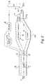
- FIG. 2 shows the case wherein the CS network comprises a CS Media GateWay (CS MGW) 17, for data transfer over a CS connection with the user terminal 1 through an intermediate Radio Network Controller (RNC) 18 and a network node 19, as known in the art.
- CS MGW CS Media GateWay
- RNC Radio Network Controller
- the CS connection by the calling user terminal 1 towards the IP Access Converter 10 now includes the step of providing a further IP address IP3 to the IP Access Converter 10 by the MGW 17.
- the further IP address IP3 is associated with the CS connection for media data transfer by the IP Access Converter 10 with the MGW 17.
- the data transfer is indicated by reference numeral 20, and the IMS signaling and CS signaling by reference numerals 9 and 16, respectively.
- the data is transported using Time Division Multiplex TDM.
- TDM Time Division Multiplex
- the data is transported using the first IP address IP1 and the second IP address IP1, the data is transported using Real Time transport Protocol (RTP).
- RTP Real Time transport Protocol
- the signaling between the MGW 17 and the MSC server 5 may be standardized Mc and the signaling between the IP Access Converter 10 and the MSC Server 6 may be standardized ISDN User Part of Signalling System 7 (ISUP)/Bearer Independent Call Control (BICC) interworking. Such as indicated in Figure 2 .
- ISUP ISDN User Part of Signalling System 7
- BICC Bearer Independent Call Control
- FIG 3 reflects the media transfer through the IP access converter 10 in the embodiment of Figure 2 using the IP addresses IP1, IP2 and IP3.
- A-party is equivalent for calling user terminal.
- the IP address of the IP access converter as illustrated in figure 3 is presently the same both for the Media Gateway (IP2) and for the A-party (also IP2). Note however that for practical purposes the IP addresses used by the MGW and the A-party could be different from each other.
- FIG 4 shows an internal table in the IP access converter 10, used for the relaying of User Plane media between the calling user terminal and the MGW of the called user terminal.
- the IP Access Converter uses the allocated IP address as index to the table, indicated by arrow 21. This is IP address IP2.
- IP address of the MGW is IP3 and the IP address of the calling party is IP1.
- the skilled person can easily identify the sequence of steps in the case that the GSM terminal 1 is the calling user terminal.
- the call may be start in the CS network by CS signaling or by IMS signaling. In both cases the call enrichments of IMS signaling are maintained.
- FIG. 5 represents schematically, in a high level overview an IMS end-to-end call between two GSM terminals 1 and 22, each with an IMS client 3 and CS client 2, associated to a first CS GSM network 25 and a second CS GSM network 26, respectively.
- the first network 25 comprises an MSC server 5 and MGW 17 in association with a first IP Access Converter 10.
- the second network 26 comprises an MSC server 23 and MGW 24 in association with a second IP Access Converter 27.
- the first and second IP Access Converters 10, 27 support media transfer over an IP network 30, such as the internet or an intranet or the IMS.
- IMS signaling is established through an IMS core and IMS service 8, and Serving GPRS Support Nodes (SGSN)/Gateway GPRS Support Node (GGSN) 28, 29.
- the IMS client of GSM terminal 1 is supported by SGSN/GGSN 28 and the IMS client of GSM terminal 22 is supported by SGSN/GGSN 29.
- the IMS signaling runs between terminal and terminal.
- the GSM terminals 1, 22 are IMS registered.
- the GSM terminals do not need to know from their call partner that the media is transferred (partially) through GSM access.
- the IMS core network and service network 8 need to know, when facilitating the exchange of IP addresses for User Plane between calling and called party, that the media is transferred (partially) through GSM access.
- the media between the two GSM terminals 1, 22 runs through the GSM networks 25 respectively 26 of the respective call parties, and through the IP network 30.
- the media transfer through the GSM networks of the respective call parties takes place in accordance with normal GSM media transfer methodology, with a difference that the calls are established towards an IP address, instead of to a destination number.
- a call may start by initiating a CS connection by the calling user terminal or by IMS signaling by the calling user terminal, ie. aspects 4 and 5, respectively.
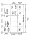
- Figure 7 shows a signalling diagram, running from top to bottom, for a call between two DTM terminals, for the case that the method according to aspect 5, CS call initiation, as described above, is applied.
- UE-A is the calling user terminal and UE-B is the called user terminal.
- IPAC-A represents the first IP Access Converter and IPAC-B represents the second IP Access Converter.
- the SIP signalling between UE-A and UE-B is indicated without reflecting all intermediate entities, such as GPRS nodes, P-CSCF, S-CSCF, SIP-AS etc. for simplicity reason in order not to hinder a clear understanding of the invention.
- the calling party's UE and the called party's UE will both terminate the CS connection with the IP Access Converter.
- the method described in the present invention does not entail the establishment of a CS speech call between the two call parties. This follows, amongst others, from the fact that there is no CS call-related signaling exchanged between the two parties.
- the CS signaling that takes place over the GSM access network and through the GSM core network, is purely meant for conveying the speech between a party in the call and an access point to the internet. All call-related signaling takes place by means of IMS signaling.
- the two call parties are identified with their IP address (for User Plane).
- the usage of CS access does not need to be indicated in the SIP signaling between the two call parties, e.g. through indication in SDP.
- the SDP may indicate codecs that may normally be used for speech call in IMS.
- the UE shall choose a CS bearer that has the same capability as the requested codec.
- the IP access converter uses the requested codec for the RTP media transfer towards the other call party. This is reflected in Fig. 6 . As a result, no special address or bearer information needs to be transported through SIP.
Landscapes
- Engineering & Computer Science (AREA)
- Computer Networks & Wireless Communication (AREA)
- Signal Processing (AREA)
- Multimedia (AREA)
- Data Exchanges In Wide-Area Networks (AREA)
- Telephonic Communication Services (AREA)
- Mobile Radio Communication Systems (AREA)
Claims (15)
- Verfahren zum Datentransfer zwischen einem ersten Benutzerendgerät (1), das eingerichtet ist zum Unterstützen von Verbindungen in einem ersten leitungsvermittelten, CS, Netzwerk (5, 25) und zum gleichzeitigen Unterstützen von Internet-Protokoll-Multimedia-System, IMS, Signalisierung und CS-Signalisierung, und einem zweiten Benutzerendgerät (7, 22), das eingerichtet ist zum Unterstützen von Sitzungen und IMS-Signalisierung in einem IMS (6, 8), wobei das erste CS-Netzwerk (5, 25) einen ersten Internet-Protokoll- (IP) Zugangswandler (10) umfasst, der eingerichtet ist zum Unterstützen von Datentransfer in dem ersten CS-Netzwerk (5, 25) und in einem IP-Netzwerk (14), wobei das Verfahren die Schritte umfasst:- Liefern von dem ersten IP-Zugangswandler (10) an das erste Benutzerendgerät (1) unter Verwendung von CS-Signalisierung (16) in dem ersten CS-Netzwerk (5, 25) einer zweiten IP-Adresse (IP2) zur Verwendung zum Datentransfer durch das zweite Benutzerendgerät (7, 22);- Bereitstellen der zweiten IP-Adresse (IP2) durch das erste Benutzerendgerät (1) für das zweite Benutzerendgerät (7, 22) unter Verwendung von Ende-zu-Ende IMS-Signalisierung (13);- Bereitstellen einer ersten IP-Adresse (IP1) zum Verwenden zum Datentransfer durch das erste Benutzerendgerät (1) durch das zweite Benutzerendgerät (7, 22) an das erste Benutzerendgerät (1) unter Verwendung von Ende-zu-Ende IMS-Signalisierung (13),- Empfangen der ersten IP-Adresse (IP1) durch den ersten IP-Zugangswandler (10) von dem ersten Benutzerendgerät (1) unter Verwendung von CS-Signalisierung (16) in dem ersten CS-Netzwerk (5, 25), und- Bereitstellen von Datentransfer zwischen dem ersten IP-Zugangswandler (10) und dem ersten Benutzerendgerät (1) durch eine CS-Verbindung (15) in dem ersten CS-Netzwerk (5, 25) und zwischen dem ersten IP-Zugangswandler (10) und dem zweiten Benutzerendgerät (7, 22) durch das IP-Netzwerk (14) unter Verwendung der ersten IP-Adresse (IP1) und der zweiten IP-Adresse (IP2).
- Verfahren nach Anspruch 1, wobei das zweite Benutzerendgerät (22) eingerichtet ist zum Unterstützen von Verbindungen in einem zweiten leitungsvermittelten, CS-, Netzwerk (26) und zum gleichzeitigen Unterstützen von IMS-Signalisierung und CS-Signalisierung, wobei das zweite CS-Netzwerk (26) einen zweiten IP-Zugangswandler (27).umfasst, der eingerichtet ist zum Unterstützen von Datentransfer in dem zweiten CS-Netzwerk (26) und einem IP-Netzwerk (30), und wobei das Verfahren weiterhin die Schritte umfasst:- Liefern der ersten IP-Adresse (IP1) von dem zweiten IP-Zugangswandler (27) an das zweite Benutzerendgerät (22) unter Verwendung von CS-Signalisierung in dem zweiten CS-Netzwerk (26),- Empfangen der zweiten IP-Adresse (IP2) durch den zweiten IP-Zugangswandler (27) von dem zweiten Benutzerendgerät (22) unter Verwendung von CS-Signalisierung in dem zweiten CS-Netzwerk (26), und wobei der Schritt des- Bereitstellens von Datentransfer umfasst Datentransfer zwischen dem ersten IP-Zugangswandler (10) und dem ersten Benutzerendgerät (1) durch eine CS-Verbindung (15) in dem ersten CS-Netzwerk (5, 25), Datentransfer zwischen dem zweiten IP-Zugangswandler (27) und dem zweiten Benutzerendgerät (22) durch eine CS-Verbindung in dem zweiten CS-Netzwerk (26), und Datentransfer zwischen den ersten und zweiten IP-Zugangswandlern (10, 27) durch das IP-Netzwerk (30) unter Verwendung der ersten IP-Adresse (IP1) und der zweiten IP-Adresse (IP2).
- Verfahren nach Anspruch 1, wobei das Verfahren die Schritte umfasst:a) Initiieren eines Anrufs unter Verwendung von Ende-zu-Ende IMS-Signalisierung (13) zwischen den ersten (1) und zweiten (7, 22) Benutzerendgeräten;
b1) Initiieren durch das erste Benutzerendgerät (1) einer ersten CS-Verbindung in dem ersten CS-Netzwerk (5, 25) in Richtung des ersten IP-Zugangswandlers (10) unter Verwendung von CS-Signalisierung (16);
b2) Zuweisen durch den ersten IP-Zugangswandler (10) in Beziehung zu der ersten CS-Verbindung der zweiten IP-Adresse (IP2) zur Verwendung zum Datentransfer durch das zweite Benutzerendgerät (7, 22);
b3) Aufbauen durch den ersten IP-Zugangswandler (10) der ersten CS-Verbindung und Bereitstellen der zweiten IP-Adresse (IP2) an das erste Benutzerendgerät (1) unter Verwendung von CS-Signalisierung (16);c) Bereitstellen der zweiten IP-Adresse (IP2) durch das erste Benutzerendgerät (1) an das zweite Benutzerendgerät (7, 22) unter Verwendung von Ende-zu-Ende IMS-Signalisierung (13);d) Bestimmen durch das zweite Benutzerendgerät (7, 22) der ersten IP-Adresse (IP1) zur Verwendung zum Datentransfer durch das erste Benutzerendgerät (1);e) Bereitstellen der ersten IP-Adresse (IP1) durch das zweite Benutzerendgerät (7, 22) an das erste Benutzerendgerät (1) unter Verwendung von Ende-zu-Ende IMS-Signalisierung (13), undf) Bereitstellen der ersten IP-Adresse (IP1) durch das erste Benutzerendgerät (1) an den ersten IP-Zugangswandler (10) in dem ersten CS-Netzwerk (5, 25) unter Verwendung von CS-Signalisierung (16). - Verfahren nach Anspruch 2 und 3, wobei der Schritt d) zum Bestimmen durch das zweite Benutzerendgerät (22) die Schritte umfasst:d1) Initiieren durch das zweite Benutzerendgerät (22) einer zweiten CS-Verbindung in dem zweiten CS-Netzwerk (26) in Richtung des zweiten IP-Zugangswandlers (27) unter Verwendung von CS-Signalisierung;d2) Zuweisen durch den zweiten IP-Zugangswandler (27) im Hinblick auf die zweite CS-Verbindung der ersten IP-Adresse (IP1) zur Verwendung zum Datentransfer durch das erste Benutzerendgerät (1);d3) Aufbauen durch den zweiten IP-Zugangswandler (27) der zweiten CS-Verbindung und Bereitstellen der ersten IP-Adresse (IP1) an das zweite Benutzerendgerät (22) unter Verwendung von CS-Signalisierung, und wobei das Verfahren weiterhin den Schritt umfasst:g) Bereitstellen der zweiten IP-Adresse (IP2) durch das zweite Benutzerendgerät (22) an den zweiten IP-Zugangswandler (27) in dem zweiten CS-Netzwerk (26) unter Verwendung von CS-Signalisierung.
- Verfahren nach Anspruch 3, wobei das zweite Benutzerendgerät (7) ein Benutzerendgerät anruft und das erste Benutzerendgerät (1) ein angerufenes Benutzerendgerät ist, wobei das zweite Benutzerendgerät (7) die Schritte d), a) und e) durchführt, so dass die erste IP-Adresse (IP1) bestimmt wird und der Anruf durch das zweite Benutzerendgerät (7) initiiert wird in Richtung des ersten Benutzerendgeräts (1) unter Verwendung von Ende-zu-Ende-IMS-Signalisierung (13), die die erste IP-Adresse (IP1) umfasst, wobei das erste Benutzerendgerät (1) die Schritte b1) und f) durchführt als Antwort auf die Anruf-Initiierung unter Verwendung von CS-Signalisierung (16), die die erste IP-Adresse (IP1) umfasst, und wobei der Anruf durch das erste Benutzerendgerät, welches den Schritt c) durchführt, aufgebaut wird.
- Verfahren nach Anspruch 3, wobei das erste Benutzerendgerät (1) ein Benutzerendgerät anruft und das zweite Benutzerendgerät (7) ein angerufenes Benutzerendgerät ist, wobei das erste Benutzerendgerät (1) den Schritt a) zur Anruf-Initiierung in Richtung des zweiten Benutzerendgeräts (7) durchführt, wobei das zweite Benutzerendgerät (7) die Schritte d) und e) als Antwort auf die Anruf-Initiierung durchführt, wobei das erste Benutzerendgerät (1) die Schritte b1) und f) durchführt unter Verwendung von CS-Signalisierung (16), die die erste IP-Adresse (IP1) umfasst, und wobei der Anruf durch das erste Benutzerendgerät (1) aufgebaut wird, das den Schritt c) durchführt.
- Verfahren nach Anspruch 3, wobei das erste Benutzerendgerät (1) ein Benutzerendgerät anruft und das zweite Benutzerendgerät (7) ein angerufenes Benutzerendgerät ist, wobei das erste Benutzerendgerät (1) die Schritte a) und b1) durchführt, so dass die zweite IP-Adresse (IP2) aufgebaut wird und der Anruf initiiert wird durch das erste Benutzerendgerät (1) in Richtung des zweiten Benutzerendgeräts (7) unter Verwendung von Ende-zu-Ende IMS-Signalisierung (13), die die zweite IP-Adresse (IP2) umfasst, und wobei der Anruf durch das zweite Benutzerendgerät (7) aufgebaut wird, das die Schritte d) und e) durchführt.
- Verfahren nach Anspruch 4, wobei das erste Benutzerendgerät (1) ein Benutzerendgerät anruft und das zweite Benutzerendgerät (22) ein angerufenes Benutzerendgerät ist, wobei das erste Benutzerendgerät (1) die Schritte a), b1), b2) und b3) durchführt, so dass die zweite IP-Adresse (IP2) aufgebaut wird und der Anruf initiiert wird durch das erste Benutzerendgerät (1) in Richtung des zweiten Benutzerendgeräts (22) unter Verwendung von Ende-zu-Ende IMS-Signalisierung (13), die die zweite IP-Adresse (IP2) umfasst, wobei das zweite Benutzerendgerät (22) die Schritte d1) und g) durchführt unter Verwendung von CS-Signalisierung, die die zweite IP-Adresse (IP2) umfasst, und wobei der Anruf durch das zweite Benutzerendgerät (22) aufgebaut wird, das den Schritt e) durchführt.
- Verfahren nach Anspruch 4, wobei das erste Benutzerendgerät (1) ein angerufenes Benutzerendgerät ist und das zweite Benutzerendgerät (22) ein Benutzerendgerät anruft, wobei das zweite Benutzerendgerät (22) den Schritt a) zur Anruf-Initiierung in Richtung des ersten Benutzerendgeräts (1) durchführt, wobei das erste Benutzerendgerät (1) die Schritte b1) und c) als Antwort auf die Anruf-Initiierung-durchführt, wobei das zweite Benutzerendgerät (22) die Schritte d1) und g) durchführt unter Verwendung von CS-Signalisierung, die die zweite IP-Adresse (IP2) umfasst, und wobei der Anruf durch das zweite Benutzerendgerät (1) aufgebaut wird, das den Schritt e) durchführt.
- Verfahren nach einem der Ansprüche 3 bis 9, wobei ein CS-Netzwerk ein Media-Gateway, MGW, (17, 24) umfasst zum Datentransfer über eine CS-Verbindung mit einem Benutzerendgerät (1, 22), wobei Initiierung einer CS-Verbindung durch das Benutzerendgerät (1, 22) in Richtung eines IP-Zugangswandlers (10, 27) Bereitstellen einer weiteren IP-Adresse (IP3) an den IP-Zugangswandler (10, 27) durch das MGW (17, 24) umfasst, wobei die weitere IP-Adresse (IP3) mit der CS-Verbindung zum Datentransfer durch den IP-Zugangswandler (10, 27) mit dem Benutzerendgerät (1, 22) verbunden ist.
- Verfahren nach einem der vorhergehenden Ansprüche, wobei Datentransfer zwischen der ersten IP-Adresse (IP1) und der zweiten IP-Adresse (IP2) über ein IP-Netzwerk bereitgestellt wird, das eines aus der Gruppe umfasst, die besteht aus einem öffentlichen IP-Netzwerk, einem privaten IP-Netzwerk und einem IMS.
- Ein Internet-Protokoll-, IP-, Zugangswandler (10) zum Unterstützen von Datentransfer in einem ersten leitungsvermittelten, CS-, Netzwerk (5, 25) und in einem IP-Netzwerk (14, 30) zum Datentransfer zwischen einem ersten Benutzerendgerät (1), das eingerichtet ist zum Unterstützen von Verbindungen in dem ersten CS-Netzwerk (5, 25) und zum gleichzeitigen Unterstützen von Internet-Protokoll-Multimedia-System, IMS, Signalisierung und CS-Signalisierung, und einem zweiten Benutzerendgerät (7, 22), das eingerichtet ist zum Unterstützen von Sitzungen und IMS-Signalisierung in einem IMS (6, 8), wobei der IP-Zugangswandler (10) eingerichtet ist zum:- Liefern an das erste Benutzerendgerät (1) unter Verwendung von CS-Signalisierung (16) in dem ersten CS-Netzwerk (5, 25) einer zweiten IP-Adresse (IP2) zum Verwenden zum Datentransfer durch das zweite Benutzerendgerät (7, 22);- Empfangen von dem ersten Benutzerendgerät (1) unter Verwendung von CS-Signalisierung (16) in dem ersten CS-Netzwerk (5, 25) einer ersten IP-Adresse (IP1) zum Datentransfer durch das erste Benutzerendgerät (1), und- Bereitstellen von Datentransfer mit dem ersten Benutzerendgerät (1) durch eine CS-Verbindung (15) in dem ersten CS-Netzwerk (5, 25) und mit dem zweiten Benutzerendgerät (7, 22) durch das IP-Netzwerk (14, 30) unter Verwendung der ersten IP-Adresse (IP1).
- Der IP-Zugangswandler (10) nach Anspruch 12, wobei der IP-Zugangswandler (10) während einer Anrufinitiierung unter Verwendung von Ende-zu-Ende-IMS Signalisierung (13) zwischen den ersten (1) und zweiten (7, 22) Benutzerendgeräten weiterhin eingerichtet ist zum:- Zuweisen der zweiten IP-Adresse (IP2)im Hinblick auf die CS-Verbindung (15) zur Verwendung zum Datentransfer durch das zweite Benutzerendgerät (7, 22), und- Aufbauen der CS-Verbindung.
- Der IP-Zugangswandler (10) nach Anspruch 12 oder 13, wobei der IP-Zugangswandler (10) eingerichtet ist zum Empfangen einer weiteren IP-Adresse (IP3) von einem Media-Gateway, NGW, (17) des CS-Netzwerks (5, 25), wobei die weitere IP-Adresse (IP3) mit der CS-Verbindung zum Datentransfer durch den IP-Zugangswandler (10) mit dem ersten Benutzerendgerät (1) verbunden ist.
- Ein Benutzerendgerät (1), eingerichtet zum Unterstützen von Verbindungen in einem leitungsvermittelten, CS-, Netzwerk (5, 25) und zum gleichzeitigen Unterstützen von Internet-Protokoll-Multimedia-System, IMS, Signalisierung und CS-Signalisierung, wobei das Benutzerendgerät (1) einen Internet-Protokoll-Multimedia-System-, einen IMS-Klienten (2) und einen CS-Klienten (3) umfasst, die wirksam verbunden (4) sind, wobei der IMS-Klient (2) eingerichtet ist zum Unterstützen von IMS-Signalisierung und wobei der CS-Klient (3) eingerichtet ist zum Unterstützen von CS-Signalisierung, dadurch gekennzeichnet, dass der IMS-Client (2) eingerichtet ist zum Empfangen einer ersten Internet-Protokoll, IP, Adresse (IP1) von einem anderen Benutzerendgerät (7, 22) durch Ende-zu-Ende-IMS Signalisierung (9) und der CS-Klient (3) eingerichtet ist zum Übermitteln der ersten IP-Adresse (IP1) an einen in dem CS-Netzwerk (5, 25) enthaltenen IP-Zugangswandler (10) unter Verwendung von CS-Signalisierung (16), und wobei der CS-Klient (3) eingerichtet ist zum Empfangen einer zweiten IP-Adresse (IP2) von dem IP-Zugangswandler (10) durch CS-Signalisierung (16) und der IMS-Klient (2) eingerichtet ist zum Übermitteln der zweiten IP-Adresse (IP2) an das andere Benutzerendgerät (7, 22) unter Verwendung von Ende-zu-Ende-IMS Signalisierung, um Daten zwischen den Endgeräten (1; 7, 22) unter Verwendung der ersten IP-Adresse (IP1) und der zweiten IP-Adresse (IP2) zu transferieren.
Applications Claiming Priority (1)
| Application Number | Priority Date | Filing Date | Title |
|---|---|---|---|
| PCT/NL2007/000111 WO2008133492A1 (en) | 2007-04-26 | 2007-04-26 | A method of and a system for establishing a call over an ip multi media communications system and a circuit switched communications system |
Publications (2)
| Publication Number | Publication Date |
|---|---|
| EP2149244A1 EP2149244A1 (de) | 2010-02-03 |
| EP2149244B1 true EP2149244B1 (de) | 2011-11-02 |
Family
ID=38924467
Family Applications (1)
| Application Number | Title | Priority Date | Filing Date |
|---|---|---|---|
| EP07747293A Not-in-force EP2149244B1 (de) | 2007-04-26 | 2007-04-26 | Verfahren und system zum herstellen eines anrufs über ein ip-multimedia-kommunikationssystem und leitungsvermitteltes kommunikationssystem |
Country Status (5)
| Country | Link |
|---|---|
| US (1) | US8879539B2 (de) |
| EP (1) | EP2149244B1 (de) |
| CN (1) | CN101658010B (de) |
| AT (1) | ATE532311T1 (de) |
| WO (1) | WO2008133492A1 (de) |
Families Citing this family (6)
| Publication number | Priority date | Publication date | Assignee | Title |
|---|---|---|---|---|
| US20080090546A1 (en) * | 2006-10-17 | 2008-04-17 | Richard Dickinson | Enhanced E911 network access for a call center using session initiation protocol (SIP) messaging |
| US20100303010A1 (en) * | 2007-10-12 | 2010-12-02 | T-Mobile International Ag | Circuit-switched call control via an ip user channel connection in the access network |
| US9621495B1 (en) * | 2012-12-10 | 2017-04-11 | Jeffrey Brian Shumate | Anonymous messaging proxy |
| CN106255075A (zh) * | 2016-07-18 | 2016-12-21 | 北京小米移动软件有限公司 | 通讯事件的处理方法及装置、电子设备 |
| CN111278082A (zh) * | 2020-01-21 | 2020-06-12 | 中移(杭州)信息技术有限公司 | 终端通信装置、方法、系统、设备及存储介质 |
| CN111600868A (zh) * | 2020-05-12 | 2020-08-28 | 捷开通讯(深圳)有限公司 | 直连通话方法、核心网设备、移动终端以及存储介质 |
Family Cites Families (7)
| Publication number | Priority date | Publication date | Assignee | Title |
|---|---|---|---|---|
| DE60024499T2 (de) * | 2000-12-22 | 2006-08-03 | Nokia Corp. | Verfahren, Endgeräte und Netzwerkeinrichtung zur Änderung eines Verbindungsparameters |
| US7286545B1 (en) * | 2002-03-26 | 2007-10-23 | Nortel Networks Limited | Service broker |
| GB0314252D0 (en) * | 2003-06-19 | 2003-07-23 | Ericsson Telefon Ab L M | Conversational bearer negotiation |
| US7961714B1 (en) * | 2004-05-11 | 2011-06-14 | Nortel Networks Limited | Providing packet-based multimedia services via a circuit bearer |
| GB2410855A (en) * | 2004-02-04 | 2005-08-10 | Vodafone Plc | Telecommunication system communication sessions |
| GB0405174D0 (en) * | 2004-03-08 | 2004-04-07 | Nokia Corp | Communication system |
| WO2009012807A1 (en) | 2007-07-20 | 2009-01-29 | Telefonaktiebolaget Lm Ericsson (Publ) | Setting up a call in a telecommunications network by addressing the destination with an uri in a circuit switched call setup request message |
-
2007
- 2007-04-26 AT AT07747293T patent/ATE532311T1/de active
- 2007-04-26 WO PCT/NL2007/000111 patent/WO2008133492A1/en not_active Ceased
- 2007-04-26 EP EP07747293A patent/EP2149244B1/de not_active Not-in-force
- 2007-04-26 CN CN2007800526941A patent/CN101658010B/zh not_active Expired - Fee Related
- 2007-04-26 US US12/597,725 patent/US8879539B2/en not_active Expired - Fee Related
Also Published As
| Publication number | Publication date |
|---|---|
| ATE532311T1 (de) | 2011-11-15 |
| CN101658010B (zh) | 2013-12-18 |
| US8879539B2 (en) | 2014-11-04 |
| US20100118862A1 (en) | 2010-05-13 |
| EP2149244A1 (de) | 2010-02-03 |
| CN101658010A (zh) | 2010-02-24 |
| WO2008133492A1 (en) | 2008-11-06 |
Similar Documents
| Publication | Publication Date | Title |
|---|---|---|
| EP1750400B1 (de) | Verfahren und Vorrichtung zur Zusammenarbeit von Multimediadiensten zwischen einem CSI Endgerät und einem IMS Endgerät | |
| EP1593250B1 (de) | Konversations-trägeraushandlung | |
| RU2434363C2 (ru) | Система, способ и устройство для реализации непрерывности мультимедийных вызовов | |
| US8213418B2 (en) | Providing packet-based multimedia services via a circuit breaker | |
| US7965704B2 (en) | Method and apparatus for handling IMS terminal's call request including request for real-time service received over IMS domain by CSI terminal | |
| EP2052522B1 (de) | Zusammenarbeit mit medien-fallback | |
| US20070121608A1 (en) | Method and System for Implementing Communications | |
| JP5255123B2 (ja) | 通信ネットワークにおいてセッションを確立する方法 | |
| EP2583476B1 (de) | Verfahren und vorrichtungen zur verwendung einer vplmn-infrastruktur über ein hplmn zur vollendung eines ims-sitzungssetups für einen roamenden nutzer | |
| EP3361714B1 (de) | Verfahren zur verarbeitung einer trägersteuerung | |
| EP2149244B1 (de) | Verfahren und system zum herstellen eines anrufs über ein ip-multimedia-kommunikationssystem und leitungsvermitteltes kommunikationssystem | |
| CN101180843A (zh) | 由多媒体核心网络进行呼叫建立的本地交换 | |
| CN101102615B (zh) | 一种ip多媒体子系统集中控制业务终呼的实现方法 | |
| CN101102613B (zh) | 一种ip多媒体子系统集中控制业务终呼的实现方法 | |
| CN101155173B (zh) | 电路域感知ims域多媒体会话媒体信息的方法及系统 | |
| CN101217797B (zh) | 一种ip多媒体子系统集中控制业务的起呼方法 | |
| CN101217796A (zh) | 一种ip多媒体子系统集中控制业务中终呼的实现方法 |
Legal Events
| Date | Code | Title | Description |
|---|---|---|---|
| PUAI | Public reference made under article 153(3) epc to a published international application that has entered the european phase |
Free format text: ORIGINAL CODE: 0009012 |
|
| 17P | Request for examination filed |
Effective date: 20091015 |
|
| AK | Designated contracting states |
Kind code of ref document: A1 Designated state(s): AT BE BG CH CY CZ DE DK EE ES FI FR GB GR HU IE IS IT LI LT LU LV MC MT NL PL PT RO SE SI SK TR |
|
| AX | Request for extension of the european patent |
Extension state: AL BA HR MK RS |
|
| 17Q | First examination report despatched |
Effective date: 20100409 |
|
| DAX | Request for extension of the european patent (deleted) | ||
| GRAP | Despatch of communication of intention to grant a patent |
Free format text: ORIGINAL CODE: EPIDOSNIGR1 |
|
| GRAS | Grant fee paid |
Free format text: ORIGINAL CODE: EPIDOSNIGR3 |
|
| GRAA | (expected) grant |
Free format text: ORIGINAL CODE: 0009210 |
|
| AK | Designated contracting states |
Kind code of ref document: B1 Designated state(s): AT BE BG CH CY CZ DE DK EE ES FI FR GB GR HU IE IS IT LI LT LU LV MC MT NL PL PT RO SE SI SK TR |
|
| REG | Reference to a national code |
Ref country code: GB Ref legal event code: FG4D |
|
| REG | Reference to a national code |
Ref country code: CH Ref legal event code: EP |
|
| REG | Reference to a national code |
Ref country code: IE Ref legal event code: FG4D |
|
| REG | Reference to a national code |
Ref country code: DE Ref legal event code: R096 Ref document number: 602007018468 Country of ref document: DE Effective date: 20120202 |
|
| REG | Reference to a national code |
Ref country code: NL Ref legal event code: T3 |
|
| LTIE | Lt: invalidation of european patent or patent extension |
Effective date: 20111102 |
|
| PG25 | Lapsed in a contracting state [announced via postgrant information from national office to epo] |
Ref country code: LT Free format text: LAPSE BECAUSE OF FAILURE TO SUBMIT A TRANSLATION OF THE DESCRIPTION OR TO PAY THE FEE WITHIN THE PRESCRIBED TIME-LIMIT Effective date: 20111102 Ref country code: IS Free format text: LAPSE BECAUSE OF FAILURE TO SUBMIT A TRANSLATION OF THE DESCRIPTION OR TO PAY THE FEE WITHIN THE PRESCRIBED TIME-LIMIT Effective date: 20120302 |
|
| PG25 | Lapsed in a contracting state [announced via postgrant information from national office to epo] |
Ref country code: PT Free format text: LAPSE BECAUSE OF FAILURE TO SUBMIT A TRANSLATION OF THE DESCRIPTION OR TO PAY THE FEE WITHIN THE PRESCRIBED TIME-LIMIT Effective date: 20120302 Ref country code: BE Free format text: LAPSE BECAUSE OF FAILURE TO SUBMIT A TRANSLATION OF THE DESCRIPTION OR TO PAY THE FEE WITHIN THE PRESCRIBED TIME-LIMIT Effective date: 20111102 Ref country code: PL Free format text: LAPSE BECAUSE OF FAILURE TO SUBMIT A TRANSLATION OF THE DESCRIPTION OR TO PAY THE FEE WITHIN THE PRESCRIBED TIME-LIMIT Effective date: 20111102 Ref country code: SE Free format text: LAPSE BECAUSE OF FAILURE TO SUBMIT A TRANSLATION OF THE DESCRIPTION OR TO PAY THE FEE WITHIN THE PRESCRIBED TIME-LIMIT Effective date: 20111102 Ref country code: SI Free format text: LAPSE BECAUSE OF FAILURE TO SUBMIT A TRANSLATION OF THE DESCRIPTION OR TO PAY THE FEE WITHIN THE PRESCRIBED TIME-LIMIT Effective date: 20111102 Ref country code: GR Free format text: LAPSE BECAUSE OF FAILURE TO SUBMIT A TRANSLATION OF THE DESCRIPTION OR TO PAY THE FEE WITHIN THE PRESCRIBED TIME-LIMIT Effective date: 20120203 Ref country code: LV Free format text: LAPSE BECAUSE OF FAILURE TO SUBMIT A TRANSLATION OF THE DESCRIPTION OR TO PAY THE FEE WITHIN THE PRESCRIBED TIME-LIMIT Effective date: 20111102 |
|
| PG25 | Lapsed in a contracting state [announced via postgrant information from national office to epo] |
Ref country code: CY Free format text: LAPSE BECAUSE OF FAILURE TO SUBMIT A TRANSLATION OF THE DESCRIPTION OR TO PAY THE FEE WITHIN THE PRESCRIBED TIME-LIMIT Effective date: 20111102 |
|
| PG25 | Lapsed in a contracting state [announced via postgrant information from national office to epo] |
Ref country code: DK Free format text: LAPSE BECAUSE OF FAILURE TO SUBMIT A TRANSLATION OF THE DESCRIPTION OR TO PAY THE FEE WITHIN THE PRESCRIBED TIME-LIMIT Effective date: 20111102 Ref country code: EE Free format text: LAPSE BECAUSE OF FAILURE TO SUBMIT A TRANSLATION OF THE DESCRIPTION OR TO PAY THE FEE WITHIN THE PRESCRIBED TIME-LIMIT Effective date: 20111102 Ref country code: CZ Free format text: LAPSE BECAUSE OF FAILURE TO SUBMIT A TRANSLATION OF THE DESCRIPTION OR TO PAY THE FEE WITHIN THE PRESCRIBED TIME-LIMIT Effective date: 20111102 Ref country code: SK Free format text: LAPSE BECAUSE OF FAILURE TO SUBMIT A TRANSLATION OF THE DESCRIPTION OR TO PAY THE FEE WITHIN THE PRESCRIBED TIME-LIMIT Effective date: 20111102 Ref country code: BG Free format text: LAPSE BECAUSE OF FAILURE TO SUBMIT A TRANSLATION OF THE DESCRIPTION OR TO PAY THE FEE WITHIN THE PRESCRIBED TIME-LIMIT Effective date: 20120202 |
|
| PG25 | Lapsed in a contracting state [announced via postgrant information from national office to epo] |
Ref country code: IT Free format text: LAPSE BECAUSE OF FAILURE TO SUBMIT A TRANSLATION OF THE DESCRIPTION OR TO PAY THE FEE WITHIN THE PRESCRIBED TIME-LIMIT Effective date: 20111102 Ref country code: RO Free format text: LAPSE BECAUSE OF FAILURE TO SUBMIT A TRANSLATION OF THE DESCRIPTION OR TO PAY THE FEE WITHIN THE PRESCRIBED TIME-LIMIT Effective date: 20111102 |
|
| PLBE | No opposition filed within time limit |
Free format text: ORIGINAL CODE: 0009261 |
|
| STAA | Information on the status of an ep patent application or granted ep patent |
Free format text: STATUS: NO OPPOSITION FILED WITHIN TIME LIMIT |
|
| REG | Reference to a national code |
Ref country code: AT Ref legal event code: MK05 Ref document number: 532311 Country of ref document: AT Kind code of ref document: T Effective date: 20111102 |
|
| 26N | No opposition filed |
Effective date: 20120803 |
|
| REG | Reference to a national code |
Ref country code: DE Ref legal event code: R097 Ref document number: 602007018468 Country of ref document: DE Effective date: 20120803 |
|
| PG25 | Lapsed in a contracting state [announced via postgrant information from national office to epo] |
Ref country code: MC Free format text: LAPSE BECAUSE OF NON-PAYMENT OF DUE FEES Effective date: 20120430 |
|
| REG | Reference to a national code |
Ref country code: CH Ref legal event code: PL |
|
| REG | Reference to a national code |
Ref country code: IE Ref legal event code: MM4A |
|
| REG | Reference to a national code |
Ref country code: FR Ref legal event code: ST Effective date: 20121228 |
|
| PG25 | Lapsed in a contracting state [announced via postgrant information from national office to epo] |
Ref country code: IE Free format text: LAPSE BECAUSE OF NON-PAYMENT OF DUE FEES Effective date: 20120426 Ref country code: LI Free format text: LAPSE BECAUSE OF NON-PAYMENT OF DUE FEES Effective date: 20120430 Ref country code: CH Free format text: LAPSE BECAUSE OF NON-PAYMENT OF DUE FEES Effective date: 20120430 Ref country code: AT Free format text: LAPSE BECAUSE OF FAILURE TO SUBMIT A TRANSLATION OF THE DESCRIPTION OR TO PAY THE FEE WITHIN THE PRESCRIBED TIME-LIMIT Effective date: 20111102 |
|
| PG25 | Lapsed in a contracting state [announced via postgrant information from national office to epo] |
Ref country code: FR Free format text: LAPSE BECAUSE OF NON-PAYMENT OF DUE FEES Effective date: 20120430 |
|
| PG25 | Lapsed in a contracting state [announced via postgrant information from national office to epo] |
Ref country code: ES Free format text: LAPSE BECAUSE OF FAILURE TO SUBMIT A TRANSLATION OF THE DESCRIPTION OR TO PAY THE FEE WITHIN THE PRESCRIBED TIME-LIMIT Effective date: 20120213 |
|
| PG25 | Lapsed in a contracting state [announced via postgrant information from national office to epo] |
Ref country code: FI Free format text: LAPSE BECAUSE OF FAILURE TO SUBMIT A TRANSLATION OF THE DESCRIPTION OR TO PAY THE FEE WITHIN THE PRESCRIBED TIME-LIMIT Effective date: 20111102 |
|
| PG25 | Lapsed in a contracting state [announced via postgrant information from national office to epo] |
Ref country code: MT Free format text: LAPSE BECAUSE OF FAILURE TO SUBMIT A TRANSLATION OF THE DESCRIPTION OR TO PAY THE FEE WITHIN THE PRESCRIBED TIME-LIMIT Effective date: 20111102 |
|
| PG25 | Lapsed in a contracting state [announced via postgrant information from national office to epo] |
Ref country code: TR Free format text: LAPSE BECAUSE OF FAILURE TO SUBMIT A TRANSLATION OF THE DESCRIPTION OR TO PAY THE FEE WITHIN THE PRESCRIBED TIME-LIMIT Effective date: 20111102 |
|
| PG25 | Lapsed in a contracting state [announced via postgrant information from national office to epo] |
Ref country code: LU Free format text: LAPSE BECAUSE OF NON-PAYMENT OF DUE FEES Effective date: 20120426 |
|
| PG25 | Lapsed in a contracting state [announced via postgrant information from national office to epo] |
Ref country code: HU Free format text: LAPSE BECAUSE OF FAILURE TO SUBMIT A TRANSLATION OF THE DESCRIPTION OR TO PAY THE FEE WITHIN THE PRESCRIBED TIME-LIMIT Effective date: 20070426 |
|
| PGFP | Annual fee paid to national office [announced via postgrant information from national office to epo] |
Ref country code: NL Payment date: 20190426 Year of fee payment: 13 |
|
| PGFP | Annual fee paid to national office [announced via postgrant information from national office to epo] |
Ref country code: DE Payment date: 20190429 Year of fee payment: 13 |
|
| PGFP | Annual fee paid to national office [announced via postgrant information from national office to epo] |
Ref country code: GB Payment date: 20190429 Year of fee payment: 13 |
|
| REG | Reference to a national code |
Ref country code: DE Ref legal event code: R119 Ref document number: 602007018468 Country of ref document: DE |
|
| REG | Reference to a national code |
Ref country code: NL Ref legal event code: MM Effective date: 20200501 |
|
| PG25 | Lapsed in a contracting state [announced via postgrant information from national office to epo] |
Ref country code: DE Free format text: LAPSE BECAUSE OF NON-PAYMENT OF DUE FEES Effective date: 20201103 |
|
| GBPC | Gb: european patent ceased through non-payment of renewal fee |
Effective date: 20200426 |
|
| PG25 | Lapsed in a contracting state [announced via postgrant information from national office to epo] |
Ref country code: NL Free format text: LAPSE BECAUSE OF NON-PAYMENT OF DUE FEES Effective date: 20200501 |
|
| PG25 | Lapsed in a contracting state [announced via postgrant information from national office to epo] |
Ref country code: GB Free format text: LAPSE BECAUSE OF NON-PAYMENT OF DUE FEES Effective date: 20200426 |