EP2149291B1 - Beeren-Erntemaschine, insbesondere Weintrauben-Erntemaschine, die mit einem Schüttelsystem ausgestattet ist, und megatronische Schüttelsteuerung dieses Systems - Google Patents
Beeren-Erntemaschine, insbesondere Weintrauben-Erntemaschine, die mit einem Schüttelsystem ausgestattet ist, und megatronische Schüttelsteuerung dieses Systems Download PDFInfo
- Publication number
- EP2149291B1 EP2149291B1 EP09358004A EP09358004A EP2149291B1 EP 2149291 B1 EP2149291 B1 EP 2149291B1 EP 09358004 A EP09358004 A EP 09358004A EP 09358004 A EP09358004 A EP 09358004A EP 2149291 B1 EP2149291 B1 EP 2149291B1
- Authority
- EP
- European Patent Office
- Prior art keywords
- shaking
- harvesting machine
- eccentric
- shakers
- berry
- Prior art date
- Legal status (The legal status is an assumption and is not a legal conclusion. Google has not performed a legal analysis and makes no representation as to the accuracy of the status listed.)
- Active
Links
Images






Classifications
-
- A—HUMAN NECESSITIES
- A01—AGRICULTURE; FORESTRY; ANIMAL HUSBANDRY; HUNTING; TRAPPING; FISHING
- A01D—HARVESTING; MOWING
- A01D46/00—Picking of fruits, vegetables, hops, or the like; Devices for shaking trees or shrubs
- A01D46/28—Vintaging machines, i.e. grape harvesting machines
Definitions
- the present invention relates to a berry harvesting machine, in particular a harvesting machine, of the kind comprising a harvesting head comprising two sets of detachment of the berries placed opposite and each consisting of a plurality of shakers or superimposed picking arms.
- These vertically spaced shakers are constituted by flexible bars and are fixed, by means of their opposite ends, on the one hand, on a vertical animation shaft and, on the other hand, on a fixed, oscillating or mounted vertical shaft crazy.
- pinching Between these two sets of detachment bays or shaking sets, is provided a vertical space generally referred to as "pinching".
- the invention is more specifically the mechatronic shaking control shaking sets of such a machine.
- the quality of the harvest obtained by a harvesting machine is still very uncertain and depends on several parameters, including human parameters of appreciation and mechanical performance parameters of the systems that make up a harvesting head of such a machine.
- the vine shaking system is by far the most important part of a harvesting machine harvesting head.
- control devices shaking systems for harvesting machines such as self-propelled harvesting machines or towed.
- These control devices are more or less sophisticated, depending on the different manufacturers and the desired levels of performance.
- non-adjustable or unadjustable shaking controls They generally consist of a connecting rod-crank system and they do not allow the essential adjustments which are the adjustment of the amplitude of the shakers and the setting of nip between the sets of shakers, if not a manual adjustment or semi Manual directly on the shaking control.
- the adjustment of the shaking frequency as for it is adjustable to the driving position on most shaking controls, because this setting is very easy to achieve and above all inexpensive. It is usually done using a hydraulic motor that drives the crank system in rotation. The rotational speed of the crank gives the number of strokes per minute in frequency setting of the shaking.
- crank-handle system has the very great disadvantage of being very rigid controls, that is to say that regardless of the conformation and hardness of the obstacles entering the device shaking, the connecting rod-crank system never stalls at the risk of mechanical damage.
- the reason for these defects is that, since the forces generated in the connecting rods can not be controlled especially when they reach the point of the Moro point of the crank system, it is difficult to size the mechanical parts to ensure reliability of the shaking control regardless of obstacles entering the shaker.
- This command is, to date, the most efficient in terms of settings at the driving position and in precision obtained. It allows the adjustment of all shaking parameters to the operator's station and with precision, whether it is the setting of the shaking frequency, the setting of the toe between the shakers or the shaker movement amplitude adjustment.
- this shaking control has the particularity that the right side and the left side of the harvesting head are not mechanically coupled, which easily allows the adjustment of the nip between the shakers of the two sets of shaking, that is, to say between the shakers of the left set and the shakers of the right set.
- the shake command described in the document FR-2 768 016 is not a crank-handle system control, it is driven by a servo-servo-servo hydraulic reciprocating system.
- This hydraulic servovalve servo-controlled hydraulic cylinder system is a big advantage especially in terms of adjustment, but also in terms of flexibility. Indeed, unlike a rod-crank system, this shaking control can wedge partially on a major obstacle, for example a large stake of vine, which enters the shaking, which is usually an advantage. On the other hand, if the vegetation is very important, the system can lack power and stall continuously what is very problematic and limiting.
- each right and left shaking assembly is independent and hydraulically and electronically controlled precisely, all adjustment possibilities on a control of this type are possible.
- the shake command described in the document FR-2 768 016 still has a rather serious disadvantage constituted by the fact that the power absorbed is much greater than that absorbed by a conventional crank-crank system.
- the over-consumption of power is of the order of 40% to 50%, which can prove to be a big problem especially on the models of machines of small power and in particular on the towed harvesting machines which are generally drawn by low power tractors.
- this additional absorbed power is converted into heat in the hydraulic oil must absolutely cool, which is an additional economic disadvantage.
- the present invention relates to a berry harvesting machine, in particular a harvesting machine, provided with a mechatronic shaking system, designed to overcome the above-mentioned disadvantages of the shaking control systems known to date. It applies in particular to machines of the kind comprising a shaking system consisting of two sets of detachment of the racks mounted vis-a-vis and each comprising a plurality of superimposed shakers constituted by flexible bars fixed by the intermediate of their ends, with two vertical shafts, at least one of which is an oscillating actuating shaft subjected to a mechatronic shaking control for imparting an oscillating movement thereto.
- a shaking system consisting of two sets of detachment of the racks mounted vis-a-vis and each comprising a plurality of superimposed shakers constituted by flexible bars fixed by the intermediate of their ends, with two vertical shafts, at least one of which is an oscillating actuating shaft subjected to a mechatronic shaking control for imparting an oscillating movement thereto
- the mechatronic shaking control according to the invention is notably remarkable in that it comprises an eccentric system connected to the actuating shaft of the shaking assemblies by means of a connecting rod and in that the axis of rotation of this eccentric drive system is mounted with an adjustable orientation in a plane parallel to the median plane of the machine, so that the modification of this orientation makes it possible to modify the amplitude of the oscillation movement of said actuating shaft .
- the mechatronic shaking control system comprises two eccentrics mounted side by side on a tilting support or cradle, these two eccentric systems being actuated in rotation simultaneously and in synchronism by a common actuator, preferably constituted by a common hydraulic motor, supported by said cradle, and by a positive drive transmission mechanical means also supported by said cradle whose pivoting is provided by an actuator and allows to obtain simultaneously and synchronously an identical orientation of the axes of eccentric rotation.
- a common actuator preferably constituted by a common hydraulic motor, supported by said cradle, and by a positive drive transmission mechanical means also supported by said cradle whose pivoting is provided by an actuator and allows to obtain simultaneously and synchronously an identical orientation of the axes of eccentric rotation.
- the mechanical means of positive drive transmission is constituted by a common gear connection comprising a gear driven by the hydraulic motor or other common actuator and meshing with a toothed wheel set on the rotation shaft of each eccentric system.
- the eccentric system, or each eccentric system is integral with a flywheel.
- the link is fixed to the eccentric system by means of a bearing housing providing the pivot function and two diametrically opposed posts and integral with said rolling housing, the axis of these pins being perpendicular to the axis of rotation of the eccentric.
- the cradle supporting the bodies of the eccentric double control is mounted with tiltability about a perpendicular axis and contributing to the axes of rotation of the left and right eccentric assemblies.
- the tilting cradle is provided at its right and left ends with pivots mounted with a rotational ability in bearings fixed laterally on the frame of the shaking system, an actuator connecting an upper element of the frame and an arm secured to the cradle, ensuring the pivoting thereof.
- the shaking shafts of the shaking assemblies are mounted with oscillatory movement ability around their longitudinal axis and limited amplitude swinging around a point in their lower part.
- each oscillating-tilting shaking shaft is mounted in a ball bearing housed with a latitude of displacement in a slide rigidly secured to the frame of the shaking system of the machine.
- each oscillating-tilting shaking shaft is mounted through an elastic bearing or through a ball bearing.
- the movable upper swivel bearing of each actuating shaft is connected to a force control cylinder.
- the mechatronic shaking control according to the invention allows, with precision, all the desirable settings to achieve the expected work quality of the shaking device of the machine. It also allows for controlled, intelligent flexibility and does not consume more power than a conventional rod-and-crank drive, while transmitting as much power to the vegetation.
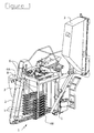
- FIG. 1 On the figure 1 is represented, in a simplified manner, a harvesting machine comprising, in a manner known per se, a gantry-shaped frame, a harvesting head 1 carried by said frame and comprising two shaking assemblies facing each other, two conveying systems 2 for the receipt and delivery of the harvest to two receiving bins 3 installed laterally and in the upper part of the frame.
- the latter is equipped with wheels (not shown) and the machine further comprises a motor and control systems (also not shown) for respectively driving and controlling the operation of its various active organs.
- a machine can be self-propelled or attachable to a tractor vehicle, for example an agricultural tractor.
- the harvesting head 1 is installed, preferably removably, inside the gantry or tunnel constituted by the frame of the machine.
- a shaking system consisting of two detachment assemblies of the berries 4A and 4B mounted vis-a-vis and each comprising a plurality of superimposed picking arms or shakers 5.
- These vertically spaced shakers are, for example, constituted by flexible bars fixed, via their ends, on the one hand, to a first vertical shaft 6 mounted with oscillation ability about its longitudinal axis a4, on the frame 7 of the shaking system, and, on the other hand, to a second vertical shaft 8 which is preferably fixed with respect to said frame 7, but which could be installed with a motorized oscillation ability or mounted idle.
- the superimposed shakers 5 of each shaking assembly 4A, 4B are slightly vertically offset from the shakers of the other shaking assembly disposed vis-a-vis.
- the shakers 5 have the general shape of a hairpin consisting of two branches 5a, 5b slightly divergent connecting by a curved portion, the end of one of these branches or animation branch being intended to be connected to an actuating system (shaft 6), while the end of the other of said branches constituting the active branch of the shaker being intended to be attached to a fixed support (shaft 8).
- These flexible shakers are performed in a semi-rigid material, for example polyamide or other material having similar characteristics of flexibility and flexural strength (eg polyester, fiberglass, etc.).
- the active branch of these shakers has a length greater than the length of the animation branch thereof, and it has an extreme portion curved towards the longitudinal axis of said animation branch.
- the main components of the mechatronic shaking control according to the invention are arranged above the shaking assemblies 4A and 4B.
- each shaker animation shaft 6 is carried out by means of an eccentric system 9 connected to said shaft via a rod 10, and axis of rotation a1 of this eccentric system is mounted with an adjustable orientation, so that the modification of this orientation makes it possible to modify the amplitude of oscillation of said shaft and, consequently, the amplitude of the shaking movement of shakers 5 attached to said animation tree 6.
- two eccentric systems 9 are mounted side by side on a tilting support 11 called “cradle” in the remainder of this description. These two eccentric systems 9 being actuated in rotation simultaneously and synchronously about the axes a1 by a common actuator, preferably by a common hydraulic motor 12, supported by said cradle 11, and a positive-drive mechanical transmission means, for example a common gear connection housed between the two eccentric systems 9.
- This gear connection common to both eccentric systems makes it possible to synchronize in rotation the two eccentric systems along the axes of rotation a1 and, consequently, ensures the synchronism of oscillation of the two left and right shaking shafts 6, by through the left and right links 10.
- the common gear connection comprises, for example, a toothed wheel 13 driven by the hydraulic motor 12 and meshing with a toothed wheel 14 keyed on the rotation shaft 9a of each eccentric system 9.
- the common actuator 12 could be constituted by a motor other than a hydraulic motor, for example by an electric motor.
- Each eccentric system is integral with a flywheel 15, for example mounted above the gear 14 of said system.
- the rod 10 is fixed to the eccentric system 9 by means of a bearing housing 16 providing the pivot function and two tenons 17 diametrically opposed and integral with said rolling case.
- the axis a2 of these tenons is perpendicular to the axis of rotation a1 of the eccentric system.
- the synchronized assembly and operation of the two eccentric systems 9 arranged side by side and with parallel axes of rotation a1 make it possible to precisely adjust the range of motion of all the shakers 5 fixed on the shaking shafts. left and right 6 via the left and right links 10.
- the cradle 11 supporting the bodies of the double eccentric control is mounted with tiltability about a perpendicular axis a3 and contributing to the axes a1 of rotation of the left and right eccentric assemblies 9.
- the tilting cradle 11 is provided, at its right and left ends, pivots 18 mounted with a rotational ability in bearings 19 fixed laterally on the frame 7 of the shaking system.
- the pivoting of the cradle is obtained by means of an actuator 20, for example constituted by a hydraulic, electric or pneumatic cylinder.
- This jack 20 connects, for example, an upper member 7a of the frame 7 and an arm 11a rigidly secured to the cradle 11.
- the upper member 7a may be constituted by a plate also supporting the trifunction force control cylinders described herein. -after, and in the rear part of which is formed an opening for mounting the support plate constituting the cradle 11.
- the pivoting of the cradle 11 makes it possible to modify the orientation of the axes of rotation a1 of the right and left eccentrics 9 in planes P1 parallel to the median plane PL ( figure 11 ) of the shaking system 4A-4B of the machine, so that this orientation modification makes it possible to modify, simultaneously and in synchronism, the amplitude of the oscillation movement of the actuating shafts 6 of said shaking system and, by Consequently, the amplitude of the shaking movement of all the shakers 5 attached to the actuation or animation shafts of said shaking system 4A-4B.
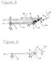
- the operating principle of the device described above is simple. If it is desired to reduce the amplitude of the movement of the shaking assemblies 4A, 4B, it suffices to rotate the cradle 11 supporting the eccentric systems 9 around the axis of rotation a3 with the aid of said actuator 20 in order to to reduce the angle ⁇ resulting from the rotational movement and situated between the planes Y 0 constituted by the two left and right axes a1 and the horizontal plane X 0 passing through the horizontal axis a1 of the support cradle assembly 11- eccentric system 9 ( figure 6 to 9 ).
- FIG. 6 and 7 is diagrammatically represented the cradle support system 11-eccentric system 9 in adjustment position of the maximum amplitude, that is to say with an angle ⁇ close to 90 °, while on Figures 8 and 9 Diagrammatically, the support cradle 11-eccentric system assembly 9 in the position of adjustment of the amplitude "mini", that is to say with a minimum angle ⁇ .
- Tilting the support cradle 11-eccentric device assembly 9 along the angle ⁇ results in an inclination BB 'having the value twice that of the eccentric e, that is to say 2e, as illustrated in FIG. the Figures 4 to 7 .
- the length of the segment B-B ' is substantially equal to the segment D-D', itself even equal to the displacement value d of the link of the rod 10 on the shaking shaft 6.
- segment D-D ' can not be greater than the segment B-B', it is therefore in the position of maximum amplitude adjustment of the shakers 5, as illustrated in FIG. figure 11 .
- the length of the segment B-B ' that is to say 2e, does not change, because it is a constant.
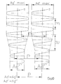
- the length of the segment DD 'decreases which therefore causes a decrease in the displacement d of the connection of the link 10 on the shaft 6, and consequently causes a decrease in the animation angle Ag of the the amplitude of the movement of the shaker shaft 6 and the shakers 5 at the arbitrary reference point C1 of a shaker 5, as illustrated in FIG. figure 12 .
- the figure 10 represents the theoretical trajectory of the arbitrary reference point C1 of the left and right shakers 5 during a setting operation for decreasing the amplitude of the movement of the shaker tree 6 and the shakers 5 during the rotation animation of the two left and right eccentric systems.
- the first part (upper part of the curve) represents the trajectory of the points C1 in maximum amplitude according to a rotation frequency F of the left and right eccentrics synchronized.
- the distance between the two reference points C1 of the left and right shakers 5 is what is called the setting of the pinch P.
- the shaking shafts 6 of the shaking assemblies 4A, 4B are mounted with a movement ability oscillatory, of the order of 10 ° to 12 °, about their longitudinal axis a4 and tilting limited amplitude around a point in their lower part.
- each shaking shaft 6 is mounted in a bearing. with ball 21 housed with a rectilinear motion ability front-rear in a slide 22 rigidly secured to the frame 7 of the shaking system of the machine.
- each shaking shaft 6 is mounted through a ball bearing or an elastic bearing 23 ( Figure 16A, 16B ) which may be constituted by a pivot of the type known as "Rosta” ® mounted in the lower part of the frame 7.
- This elastic bearing provides an oscillating connection of the shaking shaft 6 while allowing a certain degree of freedom such as a slight tilting forward or rear r in the axis of movement of the upper ball bearing 21 induced by the slide 22 as shown on the figure 16A .
- This particular movement with a very small tilting angle value, for example of the order of 0.5 ° to 1 °, makes it possible to rotate the shaker shaft along its axis of animation a4, in order to perform all pinch adjustments P, effort control, avoidance of large stakes and opening fragile stakes, and whatever the position of the rod 10 according to the angular position of the axis of rotation of the eccentric system 9.
- the shaking shafts 6 can be animated by a tilting oscillating combined movement consisting of a rotation about a principal axis a4 and a front or rear tilting of limited amplitude oriented in the axis of the slide 22, around a point located in their lower part and materialized by the bearing 23.
- each spherical bearing 21 right or left is provided by a jack 24 right or left control effort connected to said movable bearing.
- They comprise a cylindrical body 25 in which two pistons 26 and 27 are accommodated with an axial displacement ability.
- the piston 27 is rigidly secured to a rod 28 whose end 28a emerging from the cylindrical body 25 is fixed to the movable ball bearing 21 in which is mounted the upper end of the actuating shafts 6.
- This line 32 communicates with an inlet of hydraulic oil under pressure controlled by an electro-distributor 45.
- the pinch piston 26 also defines, by its opposite face, a third chamber 35 communicating, on the one hand, with a pressure oil inlet controlled by an electro-distributor 36a (right side) and by an electro-distributor 36b (left side) and, on the other hand, with the pressure sensor 30.
- This function is provided by the supply of oil volume of the first chamber 35 of the cylinders 24 right or left.
- the principle is simple, simply move the ball bearing 21 in its slide 22, for example towards the front of the machine and in the axis of said slide to generate a tilting of the shaking shaft 6, around its fixing in the lower part (bearing 23), for the same position of the rod 10.
- This switching is measured by potentiometric angular sensors 37 on the right side and on the left side, for example installed at the upper end of the actuating shafts 6. To do this, it is sufficient to simultaneously drive the electro-distributors 36a right and 36b left of the hydraulic control circuit and also a third electro-distributor 38 of said circuit, simultaneously, to obtain the displacement of the piston 26, itself bearing on the piston rod 27 maintaining the ball bearing 21 in the slide 22. This displacement is measured by the potentiometric sensors 37 for the right and left sides, in order to ensure a closed position control servo loop between the electro-distributors 36a, 36b, 38, and said potentiometric sensors 37.
- This function is intended to ensure the static hold of the left and right ball bearings 21 in the axis of the rails 22 and resting on the internal pinch adjustment piston 26 of the cylinders 24 right and left, up to a certain the force measured by the pressure sensors 30, measuring a resulting pressure of the forces due to the mechanical inertia feedback of the shaker shaft 6 of the shaker assembly 4A or 4B and the support shakers 5 on vegetation, vine stumps or trellis stakes.
- the resulting pressure Pc in the nip adjustment chamber 35 of the right and left cylinders 24 is continuously measured, for example, 100 times per second, so as to ensure that the minimum measured pressure is not below the programmed threshold pressure Ps, for example 7 bar.
- This "mini" threshold pressure can be crossed only in the case where all the shakers 5 collide with a large vine post V, as shown in FIG. figure 20 in order to preserve the eccentric systems of the shaking control and to transmit only the efforts required to shake the vegetation Ve.
- the system is auto-adaptive. Indeed, the pressure measurement in the chamber 29 of the right and left cylinders 24 is directly proportional to the number of shakers 5 mounted on the shaking shafts 6 and the vigor of vegetation Ve which must be shaken.
- a calculator 39 is connected to the right and left pressure sensors 30 and according to the pressure measurements explained above, decides to inflate or deflate the hydraulic pressure Pa of the force control in the chamber 29 by controlling the electro-distributors. 46, 38 and inflating a reference oleo-elastic battery 40 at an elastic pressure Pa and measured by a dedicated pressure sensor 41.
- the figure 13 represents the force control cylinder 24 in the minimum adjustment position of the gripping P shakers 5.
- the dimension h is equal to zero.
- the figure 14 represents the force control cylinder 24 in the intermediate adjustment position of the pinch P.
- the piston 26 is detached from the bottom of the chamber 32 at a distance h from said bottom to zero.
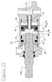
- the figure 15 represents the force control cylinder 24 with the piston 26 in the same position but with the force control holding piston 27 detached from the pinch adjustment piston 26 in the case, for example, where all the shakers 5 meet a big stake of vine V.
- control rod piston 27 returns to its initial position in contact with the piston 26 for adjusting the nip of the shakers 5.
- the precision of adjustment of the nip between the shakers 5 remains intact and unchanged.
- the opening order comes from the computer 39 and information transmitted thereto by picket detectors 47 connected to said computer and mounted on the front end or near the front end of the active branch 5a of at least one of the shakers of each shaking assembly 4A and 4B, preferably on the upper shaker 5 'of each set.
- This picket detector may consist of a shock sensor known per se, such as, for example, an accelerometer.
- the front end of the active branch of the shaker being fixed to the shaft 8 via devices known as "silentblocs" ® 48 ( figure 2 ).
- the invention also relates to a mechatronic shaking control method of berry harvesting machines, in particular harvesting machines, of the type comprising a shaking system 4A-4B consisting of two sets of detachment of the berries 4A, 4B mounted in screws.
- the oscillating actuating shafts 6 are actuated by means of two eccentric systems 9 mounted on a tilting support or cradle 11 and in that these two eccentric systems 9 are actuated by rotation, simultaneously and in synchronism, by means of a common actuator 12, preferably constituted by a hydraulic motor, installed on said cradle 11, and a positive-drive mechanical transmission means 13, 14, also mounted on said cradle whose pivoting is carried out by an actuator 20 and makes it possible to obtain, simultaneously and in synchronism, an identical orientation of the axes of rotation a1 of the eccentrics and, in this way, to adjust the amplitude of the shaking movement of all the shakers 5 shaking system 4A-4B.
- a common actuator 12 preferably constituted by a hydraulic motor, installed on said cradle 11, and a positive-drive mechanical transmission means 13, 14, also mounted on said cradle whose pivoting is carried out by an actuator 20 and makes it possible to obtain, simultaneously and in synchronism, an identical orientation of the axes of
Landscapes
- Life Sciences & Earth Sciences (AREA)
- Environmental Sciences (AREA)
- Apparatus Associated With Microorganisms And Enzymes (AREA)
- Transmission Devices (AREA)
Claims (19)
- Beerenerntemaschine, insbesondere Traubenerntemaschine, von der Art, die ein Schüttelsystem enthält, das aus zwei Einheiten zum Ablösen der Beeren (4A, 4B) besteht, die einander gegenüber montiert sind und je eine Vielzahl von übereinander angeordneten Schüttlern (5) aufweisen, die zum Beispiel aus elastischen Stäben bestehen, welche über ihre Enden an zwei senkrechten Wellen (6, 8) befestigt sind, von denen mindestens eine (6) eine schwingende Betätigungswelle ist, die an einer mechatronischen Schüttelsteuerung befestigt ist, welche es ermöglicht, ihr eine Schwingbewegung zu verleihen, dadurch gekennzeichnet, dass diese mechatronische Schüttelsteuerung ein Exzenter-System (9) enthält, das mit der Betätigungswelle (6) mittels einer Verbindungsstange (10) verbunden ist, und dass die Drehachse (a1) dieses Exzenters (9) mit einer in einer Ebene (PI) parallel zur Mittelebene (PL) der Maschine einstellbaren Ausrichtung montiert ist, damit die Veränderung dieser Ausrichtung es ermöglicht, die Amplitude der Schwingbewegung der Betätigungswelle (6) und folglich die Amplitude der Schüttelbewegung der an der Betätigungswelle (6) befestigten Schüttler (5) zu verändern.
- Beerenerntemaschine, insbesondere Traubenerntemaschine nach Anspruch 1, dadurch gekennzeichnet, dass das mechatronische Schüttelsteuerungssystem zwei Exzenter (9) enthält, die nebeneinander auf einem schwingenden Träger oder Traggestell (11) montiert sind, wobei diese zwei Exzenter-Systeme (9) gleichzeitig und synchron von einem gemeinsamen Stellantrieb (12), der vorzugsweise aus einem von dem Traggestell (11) getragenen Hydraulikmotor besteht, und von einer mechanischen Übertragungseinrichtung mit Direktantrieb (13, 14) in Drehung versetzt werden, die ebenfalls von dem Traggestell getragen wird, dessen Schwenken von einem Stellantrieb (20) durchgeführt wird und es ermöglicht, gleichzeitig und synchron eine gleiche Ausrichtung der Drehachsen (a1) der Exzenter-Systeme (9) zu erhalten und auf diese Weise die Amplitude der Schüttelbewegung der Gesamtheit der Schüttler (5) des Schüttelsystems (4A-4B) zu regeln.
- Beerenerntemaschine, insbesondere Traubenerntemaschine nach Anspruch 2, dadurch gekennzeichnet, dass die mechanische Übertragungseinrichtung mit Direktantrieb aus einer gemeinsamen Verbindung über ein Zahnradgetriebe besteht, das ein Zahnrad (13) enthält, welches vom gemeinsamen Stellantrieb (12) angetrieben wird und mit einem Zahnrad (14) in Eingriff steht, das auf der Drehwelle (9a) jedes Exzenter-Systems (9) fixiert ist.
- Beerenerntemaschine, insbesondere Traubenerntemaschine nach einem der Ansprüche 1 bis 3, dadurch gekennzeichnet, dass das Exzenter-System (9) oder jedes Exzenter-System (9) fest mit einem Schwungrad (15) verbunden ist.
- Beerenerntemaschine, insbesondere Traubenerntemaschine nach einem der Ansprüche 1 bis 4, dadurch gekennzeichnet, dass die Verbindungsstange (10) am Exzenter-System (9) mittels eines Lagergehäuses (16), das die Funktion eines Drehzapfens gewährleistet, und zwei einander diametral gegenüberliegender und fest mit dem Lagergehäuse verbundener Zapfen (17) befestigt ist, wobei die Achse (a2) dieser Zapfen lotrecht zur Drehachse (a1) des Exzenters (9) ist.
- Beerenerntemaschine, insbesondere Traubenerntemaschine nach einem der Ansprüche 2 bis 5, dadurch gekennzeichnet, dass das die Organe der Steuerung mit doppeltem Exzenter tragende Traggestell (11) mit einer Kippfähigkeit um eine zu den Drehachsen (a1) der linken und der rechten Exzenter-Einheit (9) lotrechte und kreuzende Achse (a3) montiert ist.
- Beerenerntemaschine, insbesondere Traubenerntemaschine nach Anspruch 6, dadurch gekennzeichnet, dass das kippende Traggestell (11) an seinen rechten und linken Enden mit Drehzapfen (18) versehen ist, die drehfähig in Lagern (19) montiert sind, die seitlich am Gestell (7) des Schüttelsystems befestigt sind, wobei ein Stellantrieb (20) ein oberes Element (7a) des Gestells (7) und einen fest mit dem Traggestell verbundenen Arm (11a) verbindet, was dessen Schwenken gewährleistet.
- Beerenerntemaschine, insbesondere Traubenerntemaschine nach einem der Ansprüche 1 bis 7, dadurch gekennzeichnet, dass die Schüttelwellen (6) der Schütteleinheiten (4A, 4B) mit einer Fähigkeit der Schwingbewegung um ihre Längsachse (a4) und des Kippens mit begrenzter Amplitude um einen Punkt (23) montiert sind, der sich in ihrem unteren Bereich befindet.
- Beerenerntemaschine, insbesondere Traubenerntemaschine nach Anspruch 8, dadurch gekennzeichnet, dass der obere Bereich jeder schwingenden-kippenden Schüttelwelle (6) in einem Kugelgelenklager (21) montiert ist, das in einer Gleitschiene (22) untergebracht ist, die starr mit dem Gestell (7) des Schüttelsystems der Maschine verbunden ist.
- Beerenerntemaschine, insbesondere Traubenerntemaschine nach einem der Ansprüche 8 oder 9, dadurch gekennzeichnet, dass der untere Bereich jeder schwingenden-kippenden Schüttelachse (6) über ein elastisches Lager (23) oder über ein Kugelgelenklager montiert ist.
- Beerenerntemaschine, insbesondere Traubenerntemaschine nach einem der Ansprüche 9 oder 10, dadurch gekennzeichnet, dass das obere bewegliche Kugelgelenklager (21) jeder Betätigungswelle (6) mit einem Kraftsteuerungszylinder (24) verbunden ist.
- Beerenerntemaschine, insbesondere Traubenerntemaschine nach Anspruch 11, dadurch gekennzeichnet, dass der Kraftsteuerungszylinder (24) eingerichtet ist, um drei Funktionen zu erfüllen:- eine Kraftsteuerungsfunktion des beweglichen Kugelgelenklagers (21) zur oberen Befestigung jeder rechten oder linken Schüttelwelle (6);- eine Einstellfunktion des Klemmabstands (P) zwischen der rechten und der linken Schütteleinheit (4A, 4B);- eine Funktion des schnellen Öffnens des Schüttelsystems.
- Beerenerntemaschine, insbesondere Traubenerntemaschine nach Anspruch 12, dadurch gekennzeichnet, dass jeder Kraftsteuerungszylinder mit drei Funktionen (24) einen zylindrischen Körper (25) enthält, in dem zwei zur axialen Verschiebung fähige Kolben (26 und 27) untergebracht sind, wobei einer (27) dieser Kolben starr mit einer Stange (28) verbunden ist, deren aus dem zylindrischen Körper (25) vorstehendes Ende (28a) am beweglichen Kugelgelenklager (21) befestigt ist, und eine erste Kammer (29) begrenzt, die mit einem Drucksensor (30) verbunden ist, wobei die Stange/der Kolben (27-28) ebenfalls mit dem Klemmabstand-Kolben (26) eine zweite Kammer (31) begrenzt, die mit einer Versorgungs- und Druckleitung (32) des hydraulischen Kreislaufs, zum Beispiel über eine axiale Hohlstange (33), die den Klemmabstand-Kolben (26) von einer Seite zur anderen durchquert, in Verbindung steht, wobei diese Leitung andererseits mit einer Zufuhr von unter Druck stehendem Hydrauliköl, die von einem Elektroverteiler (45) gesteuert wird, in Verbindung steht; wobei der Kolben (26) ebenfalls durch seine gegenüberliegende Seite eine dritte Kammer (35) begrenzt, die einerseits mit einer von einem rechtsseitigen Elektroverteiler (36a) und von einem linksseitigen Elektroverteiler (36b) gesteuerten Zufuhr von unter Druck stehendem ÖI und andererseits mit dem Drucksensor (30) in Verbindung steht.
- Beerenerntemaschine, insbesondere Traubenerntemaschine nach Anspruch 13, dadurch gekennzeichnet, dass die Verschiebungen des Klemmabstand-Kolbens (26) von Potentiometer-Sensoren (37 rechts und links) gemessen werden, die am oberen Ende der Betätigungswellen (6) eingebaut sind, um einen geschlossenen Regelkreis der Positionseinstellung zwischen den Elektroverteilern und den Potentiometer-Sensoren zu gewährleisten.
- Beerenerntemaschine, insbesondere Traubenerntemaschine nach einem der Ansprüche 12 bis 14, dadurch gekennzeichnet, dass Pfahl-Detektoren (47), die mit einem Rechner (39) verbunden sind, der die Schnellöffnungsfunktion des Schüttelsystems (4A-4B) der Kraftsteuerungszylinder (24) steuert, auf das vordere Ende oder in der Nähe des vorderen Endes des aktiven Zweigs (5a) mindestens eines der Schüttler (5) jeder Schütteleinheit (4A und 4B) montiert sind.
- Beerenerntemaschine, insbesondere Traubenerntemaschine nach Anspruch 15, dadurch gekennzeichnet, dass der Pfahl-Detektor (47) auf den oberen Schüttler (5') jeder Schütteleinheit (4A, 4B) montiert ist.
- Beerenerntemaschine, insbesondere Traubenerntemaschine nach einem der Ansprüche 15 oder 16, dadurch gekennzeichnet, dass die Pfahl-Detektoren (47) aus an sich bekannten Aufprallsensoren bestehen, zum Beispiel aus Beschleunigungsmessern, wobei das vordere Ende des aktiven Zweigs (5a) der mit einem Pfahl-Detektor (47) versehenen Schüttler mit den ortsfesten Wellen (8) der Schütteleinheiten (4A, 48) mittels Silentblock-Vorrichtungen (48) verbunden ist.
- Verfahren zur mechatronischen Schüttelsteuerung der Beerenerntemaschinen, insbesondere der Traubenerntemaschinen von der Art, die ein Schüttelsystem (4A-4B) enthält, das aus zwei einander gegenüber montierten Einheiten zum Ablösen der Beeren (4A, 4B) besteht, die je eine Vielzahl von übereinander angeordneten Schüttlern (5) aufweisen, die zum Beispiel aus elastischen Stäben bestehen, welche über ihre Enden an zwei senkrechten Wellen (6, 8) befestigt sind, von denen mindestens eine (6) eine schwingende Betätigungswelle ist, die an einer mechatronischen Schüttelsteuerung befestigt ist, die es ermöglicht, ihr eine Schwingbewegung zu verleihen, dadurch gekennzeichnet, dass diese mechatronische Schüttelsteuerung mittels eines Exzenter-Systems (9) durchgeführt wird, das mit der Betätigungswelle (6) über eine Verbindungsstange (10) verbunden ist, und dass die Amplitude der Schwingbewegung der Betätigungswelle (6) eingestellt wird, indem die Ausrichtung der Drehachse (a1) des Exzenter-Systems (9) in einer zur Mittelebene (PL) der Maschine parallellen Ebene (PI) und auf diese Weise die Amplitude der Schüttelbewegung der Gesamtheit der Schüttler (5) verändert wird.
- Verfahren nach Anspruch 18, dadurch gekennzeichnet, dass die Aktivierung der schwingenden Betätigungswellen (6) mittels zweier Exzenter-Systeme (9) durchgeführt wird, die auf einen Kippträger oder ein Traggestell (11) montiert sind, und dass diese zwei Exzenter-Systeme (9) gleichzeitig und synchron mittels eines gemeinsamen Stellantriebs (12), der zum Beispiel aus einem auf dem Traggestell (11) installierten Hydraulikmotor besteht, und einer mechanischen Übertragungseinrichtung mit Direktantrieb (13, 14) in Drehung versetzt werden, die ebenfalls auf das Traggestell montiert ist, dessen Schwenken von einem Stellantrieb (20) durchgeführt wird und es ermöglicht, gleichzeitig und synchron eine gleiche Ausrichtung der Drehachsen (a1) der Exzenter-Systeme zu erhalten, und auf diese Weise die Amplitude der Schüttelbewegung der Gesamtheit der Schüttler (5) des Schüttelsystems (4A-4B) einzustellen.
Applications Claiming Priority (1)
| Application Number | Priority Date | Filing Date | Title |
|---|---|---|---|
| FR0804408A FR2934458B1 (fr) | 2008-08-01 | 2008-08-01 | Machine de recolte de baies, en particulier machine a vendanger, pourvue d'un systeme de secouage, et commande de secouage mecatronique de ce systeme. |
Publications (2)
| Publication Number | Publication Date |
|---|---|
| EP2149291A1 EP2149291A1 (de) | 2010-02-03 |
| EP2149291B1 true EP2149291B1 (de) | 2011-06-29 |
Family
ID=40428200
Family Applications (1)
| Application Number | Title | Priority Date | Filing Date |
|---|---|---|---|
| EP09358004A Active EP2149291B1 (de) | 2008-08-01 | 2009-07-30 | Beeren-Erntemaschine, insbesondere Weintrauben-Erntemaschine, die mit einem Schüttelsystem ausgestattet ist, und megatronische Schüttelsteuerung dieses Systems |
Country Status (6)
| Country | Link |
|---|---|
| US (1) | US8511051B2 (de) |
| EP (1) | EP2149291B1 (de) |
| AU (1) | AU2009203186B2 (de) |
| ES (1) | ES2368703T3 (de) |
| FR (1) | FR2934458B1 (de) |
| NZ (1) | NZ578624A (de) |
Cited By (2)
| Publication number | Priority date | Publication date | Assignee | Title |
|---|---|---|---|---|
| CN105684645A (zh) * | 2016-01-19 | 2016-06-22 | 东北农业大学 | 旋转刷式蓝莓收获机 |
| US9549502B2 (en) | 2014-08-26 | 2017-01-24 | The Wine Group, Inc. | Conversion method of harvester picking head |
Families Citing this family (20)
| Publication number | Priority date | Publication date | Assignee | Title |
|---|---|---|---|---|
| FR2971668B1 (fr) * | 2011-02-22 | 2014-02-28 | Cnh France | Unite de recolte de fruits et machine recolteuse sur laquelle ladite unite est destinee a etre montee |
| FR2984687B1 (fr) * | 2011-12-23 | 2014-04-04 | Pellenc Sa | Procede de conduite de plantation d'oliviers adaptee a la recolte mecanique en continu des olives. |
| DE102016001565A1 (de) * | 2016-02-12 | 2017-08-17 | Carl Hoffmann Landmaschinenfachbetrieb Gmbh | Erntevorrichtung, Schüttelstab, Fahrzeug und Ernteverfahren zum Ernten von Weintrauben |
| US9992933B2 (en) * | 2016-02-15 | 2018-06-12 | David Payne | Attachment assembly for hydraulically actuated rams of a shaker head |
| US10433484B2 (en) * | 2016-05-31 | 2019-10-08 | Nexgen Ag, LLC | Independent frequency control of the shaker head of a harvester |
| CN106993445B (zh) * | 2017-05-12 | 2019-04-19 | 石河子大学 | 一种葡萄采摘装置 |
| CN110663352A (zh) * | 2018-07-02 | 2020-01-10 | 新疆农业大学 | 夹拽式红花花丝采摘装置 |
| CN109588113A (zh) * | 2018-12-26 | 2019-04-09 | 新疆农业大学 | 一种酿酒葡萄分离采摘装置 |
| CN110044565B (zh) * | 2019-05-17 | 2025-04-08 | 宁夏大学 | 简易枝条变频变幅振动机构及其操作方法 |
| USD943008S1 (en) * | 2019-06-13 | 2022-02-08 | Cnh Industrial America Llc | Shaker arm for a grape harvester |
| CN112790004B (zh) * | 2021-03-09 | 2023-04-25 | 西京学院 | 一种无人机搭载的高频振动式核桃采摘系统 |
| CN113973576B (zh) * | 2021-11-08 | 2023-03-03 | 广西壮族自治区农业科学院 | 一种圆叶葡萄半自动采收机 |
| CN114027030B (zh) * | 2021-11-10 | 2023-07-18 | 华中农业大学 | 一种曳引摇振式坚果收获机 |
| CN114342658B (zh) * | 2021-12-30 | 2023-05-09 | 山东省农业机械科学研究院 | 一种用于浆果收获的惯性振动动力装置 |
| CN114698467A (zh) * | 2022-05-18 | 2022-07-05 | 新疆理工学院 | 一种基于单片机控制的自走轮式核桃采摘机 |
| US20240251715A1 (en) * | 2023-01-27 | 2024-08-01 | Michigan Blueberry Growers Association | Berry harvesting mechanism |
| CN115968648B (zh) * | 2023-03-21 | 2023-06-06 | 山西农业大学 | 一种沙棘采收装置 |
| CN117958032B (zh) * | 2024-01-19 | 2026-01-09 | 中国农业大学 | 一种加工葡萄自适应柔性采收装置与监控方法 |
| WO2025181780A1 (en) * | 2024-03-01 | 2025-09-04 | Volentieri Pellenc S.R.L. | Hydraulic unit for shaking groups of harvesting machines |
| WO2025243209A1 (en) * | 2024-05-21 | 2025-11-27 | Volentieri Pellenc S.R.L. | Improved shaking element, support means for a shaking element and harvesting machine including the same |
Family Cites Families (35)
| Publication number | Priority date | Publication date | Assignee | Title |
|---|---|---|---|---|
| US3385042A (en) * | 1963-10-28 | 1968-05-28 | Oeco Corp | Berry harvester |
| US3344591A (en) * | 1964-04-27 | 1967-10-03 | Oeco Corp | Moving carriage mechanical berry harvester with rotationally oscillative shakers |
| US3727388A (en) * | 1971-08-16 | 1973-04-17 | L Smith | Grape harvester |
| US3911653A (en) * | 1972-04-10 | 1975-10-14 | Chisholm Ryder Co Inc | Machine for harvesting fruit grown on plants arranged in a row |
| US4063406A (en) * | 1973-02-08 | 1977-12-20 | Chisholm-Ryder Company, Inc. | Harvesting machine |
| US4022001A (en) * | 1975-02-03 | 1977-05-10 | Chisholm-Ryder Company, Inc. | Grape harvester |
| US4016711A (en) * | 1975-06-09 | 1977-04-12 | Up-Right, Inc. | Vine-fruit harvesting machine with inclined-tip striker rods |
| US4114463A (en) * | 1975-07-09 | 1978-09-19 | New Zealand Inventions Development Authority | Drive means and harvesting apparatus incorporating same |
| US4236371A (en) * | 1978-10-02 | 1980-12-02 | Up-Right, Inc. | Picking device for harvesting machines |
| US4250700A (en) * | 1979-06-15 | 1981-02-17 | Up-Right, Inc. | Shaker-striker vine harvester |
| US4336682A (en) * | 1980-08-15 | 1982-06-29 | Fmc Corporation | Continuous harvester for plants grown in rows |
| US4750322A (en) * | 1986-06-18 | 1988-06-14 | Korvan Industries, Inc. | Apparatus for dislodging and collecting produce from upstanding crops |
| FR2605488B1 (fr) * | 1986-10-27 | 1989-03-31 | Braud Sa | Machine pour la recolte des fruits, baies et similaires portes par des arbres et arbustes fruitiers plantes en ligne |
| FR2605487B1 (fr) * | 1986-10-27 | 1989-03-31 | Braud Sa | Machine pour la recolte des fruits, baies et similaires portes par des arbres et arbustes fruitiers plantes en ligne |
| FR2635942B1 (fr) * | 1988-09-05 | 1990-11-09 | Poly Vecture | Machine a recolter les baies et notamment a vendanger |
| US4959950A (en) * | 1988-10-19 | 1990-10-02 | U.R. Engineering Pty. Ltd. | Harvester for grapes |
| US4974405A (en) * | 1989-10-06 | 1990-12-04 | Littau Eugene G | Harvester with rotationally oscillatable cylindrical shakers |
| US5074108A (en) * | 1990-08-13 | 1991-12-24 | American Grape Harvesters, Inc. | Fruit harvesting machine |
| US5259177A (en) * | 1991-07-30 | 1993-11-09 | Donald Windemuller | Blueberry picking machine |
| NZ240461A (en) * | 1991-11-04 | 1994-12-22 | Donald John Nairn | U-shaped shaker rod for grape or fruit harvester: rod constructed in two parts having different rigidities |
| GB2291330A (en) * | 1994-07-12 | 1996-01-24 | New Holland Nv | Shaking fruit from plants |
| US5495708A (en) * | 1994-08-31 | 1996-03-05 | Fmc Corporation | Canopy harvester with force balanced drive |
| AU714747B2 (en) * | 1996-07-08 | 2000-01-13 | U R Machinery (Sales) Pty Ltd | Grape picking head and drive therefor |
| FR2768017B1 (fr) * | 1997-09-05 | 2000-05-19 | Pellenc Sa | Machine et procede de recolte de baies |
| FR2768016B1 (fr) * | 1997-09-05 | 1999-10-08 | Pellenc Sa | Machine et procede de recolte selective de baies |
| FR2768015B1 (fr) * | 1997-09-07 | 1999-10-29 | Pellenc Sa | Procede de recolte selective controlee de baies, et machines de recolte faisant application de ce procede |
| US6003294A (en) * | 1998-05-04 | 1999-12-21 | Ag - Right Enterprises | Crop harvesting rod array |
| FR2789262B1 (fr) * | 1999-02-05 | 2001-04-06 | New Holland Braud Sa | Machine pour la recolte des fruits, baies et similaires portes par des arbres et arbustes fruitiers plantes en ligne, et tige de secouage pour une telle machine |
| FR2813493A1 (fr) * | 2000-09-05 | 2002-03-08 | New Holland Braud Sa | Dispositif de recolte avec secoueurs debrayables pour machine a recolter des fruits, baies et similaires |
| FR2855366B1 (fr) * | 2003-05-27 | 2005-07-15 | Cnh France Sa | Dispositif de recolte avec biellettes flexibles pour machine a recolter des fruits, baies et similaires |
| US7350346B2 (en) * | 2004-07-13 | 2008-04-01 | Oxbo International Corporation | Tree follower |
| FR2888466B1 (fr) * | 2005-07-12 | 2008-12-05 | Pellenc Sa | Tete de recolte enjambeuse a auto-centrage pour machine de recolte de petits fruits, et machine equipee d'une telle tete de recolte. |
| FR2920277B1 (fr) * | 2007-08-30 | 2011-03-11 | Pellenc Sa | Egrappoir lineaire a mouvements oscillants alternatifs |
| FR2934459B1 (fr) * | 2008-08-01 | 2011-11-18 | Pellenc Sa | Secoueur a raideur reglable pour machines de recolte et machines de recolte faisant application de tels secoueurs. |
| FR2939273B1 (fr) * | 2008-12-10 | 2011-02-11 | Pellenc Sa | Machine de recolte de petits fruits produits en arboriculture fruitiere |
-
2008
- 2008-08-01 FR FR0804408A patent/FR2934458B1/fr not_active Expired - Fee Related
-
2009
- 2009-07-16 US US12/504,599 patent/US8511051B2/en active Active
- 2009-07-24 NZ NZ578624A patent/NZ578624A/en unknown
- 2009-07-30 ES ES09358004T patent/ES2368703T3/es active Active
- 2009-07-30 EP EP09358004A patent/EP2149291B1/de active Active
- 2009-07-31 AU AU2009203186A patent/AU2009203186B2/en not_active Ceased
Cited By (4)
| Publication number | Priority date | Publication date | Assignee | Title |
|---|---|---|---|---|
| US9549502B2 (en) | 2014-08-26 | 2017-01-24 | The Wine Group, Inc. | Conversion method of harvester picking head |
| US9730388B2 (en) | 2014-08-26 | 2017-08-15 | The Wine Group, Inc. | Parallel oscillating rails of a shaker harvester |
| CN105684645A (zh) * | 2016-01-19 | 2016-06-22 | 东北农业大学 | 旋转刷式蓝莓收获机 |
| CN105684645B (zh) * | 2016-01-19 | 2017-07-28 | 东北农业大学 | 旋转刷式蓝莓收获机 |
Also Published As
| Publication number | Publication date |
|---|---|
| ES2368703T3 (es) | 2011-11-21 |
| EP2149291A1 (de) | 2010-02-03 |
| AU2009203186A1 (en) | 2010-02-18 |
| NZ578624A (en) | 2010-11-26 |
| AU2009203186B2 (en) | 2014-03-27 |
| FR2934458B1 (fr) | 2010-09-03 |
| US20100024373A1 (en) | 2010-02-04 |
| FR2934458A1 (fr) | 2010-02-05 |
| US8511051B2 (en) | 2013-08-20 |
Similar Documents
| Publication | Publication Date | Title |
|---|---|---|
| EP2149291B1 (de) | Beeren-Erntemaschine, insbesondere Weintrauben-Erntemaschine, die mit einem Schüttelsystem ausgestattet ist, und megatronische Schüttelsteuerung dieses Systems | |
| EP0267829B1 (de) | Erntemaschine für Früchte, Beeren und ähnliche, getragen von Bäumen und Sträuchern in Reihenaufstellung | |
| EP2149290B1 (de) | Schüttler mit regulierbarer Stärke für Erntemaschinen und Erntemaschinen, bei denen solche Schüttler zum Einsatz kommen | |
| EP1116432B1 (de) | Tragbares Gerät zum Ernten von Kleinfrüchten wie Oliven, Mandeln, Kaffeekirschen | |
| EP0266259B1 (de) | Erntemaschine für Früchte, Beeren und ähnliche, getragen von Bäumen und Sträuchern in Reihenaufstellung | |
| EP0900519B1 (de) | Maschine und Verfahren für die selektive Ernte von Beeren | |
| EP2412253B1 (de) | Entrappmaschine, die einen Käfig umfasst | |
| EP2196080B1 (de) | Erntemaschine für kleine Früchte im Obstanbau | |
| FR3045272A1 (fr) | Machine recolteuse de fruits | |
| EP2062472B1 (de) | Werkzeughalter, der das Ausweichen eines Hindernisses in einer Reihe ermöglicht | |
| FR1464346A (fr) | Moissonneuse perfectionnée pour cannes à sucre | |
| FR2808708A1 (fr) | Rampe de pulverisation pour le traitement de vegetaux places en ligne | |
| EP1790211B1 (de) | Vorschneidemaschine mit integrierten Ausweichmitteln für Pfähle oder ähnliches | |
| EP3612016B1 (de) | Schwadbelüftervorrichtung und mit solch einer vorrichtung ausgestattete landwirtschaftliche maschine | |
| FR2571210A1 (fr) | Machine de recolte de fruits, baies et similaires pour cultures plantees en ligne | |
| EP3646704A1 (de) | Landwirtschaftliche rollenrüttelvorrichtung | |
| EP1269826B1 (de) | Heuwerbungsmaschine | |
| FR2638601A1 (fr) | Dispositif de secouage pour machine a recolter les baies | |
| FR2729818A1 (fr) | Machine automatique destinee a assurer la chute des fruits avant le ramassage | |
| FR2508349A1 (fr) | Dispositif pulverisateur, en particulier pour le traitement des plantes | |
| FR2559994A1 (fr) | Procede de vendange et machine a vendanger | |
| FR2886095A1 (fr) | Moissonneuse comportant un support pour montage sur tracteur et des mecanismes de fauchage a droite et a gauche du support | |
| FR2950223A1 (fr) | Dispositif d'epamprage vertical a brosses multiples | |
| FR3002109A3 (fr) | Machine interceps pour le travail de la terre | |
| FR2615348A1 (fr) | Faucheuse a appareil de coupe sur bras |
Legal Events
| Date | Code | Title | Description |
|---|---|---|---|
| PUAI | Public reference made under article 153(3) epc to a published international application that has entered the european phase |
Free format text: ORIGINAL CODE: 0009012 |
|
| AK | Designated contracting states |
Kind code of ref document: A1 Designated state(s): DE ES FR IT |
|
| AX | Request for extension of the european patent |
Extension state: AL BA RS |
|
| 17P | Request for examination filed |
Effective date: 20100302 |
|
| RIC1 | Information provided on ipc code assigned before grant |
Ipc: A01D 46/28 20060101AFI20101116BHEP |
|
| GRAP | Despatch of communication of intention to grant a patent |
Free format text: ORIGINAL CODE: EPIDOSNIGR1 |
|
| GRAS | Grant fee paid |
Free format text: ORIGINAL CODE: EPIDOSNIGR3 |
|
| GRAA | (expected) grant |
Free format text: ORIGINAL CODE: 0009210 |
|
| AK | Designated contracting states |
Kind code of ref document: B1 Designated state(s): DE ES FR IT |
|
| REG | Reference to a national code |
Ref country code: DE Ref legal event code: R096 Ref document number: 602009001682 Country of ref document: DE Effective date: 20110908 |
|
| REG | Reference to a national code |
Ref country code: ES Ref legal event code: FG2A Ref document number: 2368703 Country of ref document: ES Kind code of ref document: T3 Effective date: 20111121 |
|
| PLBE | No opposition filed within time limit |
Free format text: ORIGINAL CODE: 0009261 |
|
| STAA | Information on the status of an ep patent application or granted ep patent |
Free format text: STATUS: NO OPPOSITION FILED WITHIN TIME LIMIT |
|
| 26N | No opposition filed |
Effective date: 20120330 |
|
| REG | Reference to a national code |
Ref country code: DE Ref legal event code: R097 Ref document number: 602009001682 Country of ref document: DE Effective date: 20120330 |
|
| REG | Reference to a national code |
Ref country code: FR Ref legal event code: PLFP Year of fee payment: 8 |
|
| REG | Reference to a national code |
Ref country code: FR Ref legal event code: PLFP Year of fee payment: 9 |
|
| REG | Reference to a national code |
Ref country code: FR Ref legal event code: PLFP Year of fee payment: 10 |
|
| PGFP | Annual fee paid to national office [announced via postgrant information from national office to epo] |
Ref country code: FR Payment date: 20250324 Year of fee payment: 17 |
|
| PGFP | Annual fee paid to national office [announced via postgrant information from national office to epo] |
Ref country code: ES Payment date: 20250801 Year of fee payment: 17 |
|
| PGFP | Annual fee paid to national office [announced via postgrant information from national office to epo] |
Ref country code: DE Payment date: 20250729 Year of fee payment: 17 |
|
| PGFP | Annual fee paid to national office [announced via postgrant information from national office to epo] |
Ref country code: IT Payment date: 20250721 Year of fee payment: 17 |