EP2149341A2 - Elément de fixation destiné à la fixation d'un implant sur une lame d'une vertèbre - Google Patents
Elément de fixation destiné à la fixation d'un implant sur une lame d'une vertèbre Download PDFInfo
- Publication number
- EP2149341A2 EP2149341A2 EP09009747A EP09009747A EP2149341A2 EP 2149341 A2 EP2149341 A2 EP 2149341A2 EP 09009747 A EP09009747 A EP 09009747A EP 09009747 A EP09009747 A EP 09009747A EP 2149341 A2 EP2149341 A2 EP 2149341A2
- Authority
- EP
- European Patent Office
- Prior art keywords
- curved portion
- fastener
- plate
- lamina
- curved
- Prior art date
- Legal status (The legal status is an assumption and is not a legal conclusion. Google has not performed a legal analysis and makes no representation as to the accuracy of the status listed.)
- Withdrawn
Links
- 239000007943 implant Substances 0.000 title claims abstract description 51
- 206010058907 Spinal deformity Diseases 0.000 claims description 14
- 238000000926 separation method Methods 0.000 claims description 3
- 230000000284 resting effect Effects 0.000 claims description 2
- 210000000988 bone and bone Anatomy 0.000 description 33
- 238000000034 method Methods 0.000 description 28
- 238000002513 implantation Methods 0.000 description 10
- 210000000278 spinal cord Anatomy 0.000 description 8
- 230000003412 degenerative effect Effects 0.000 description 5
- 230000006978 adaptation Effects 0.000 description 4
- 210000003484 anatomy Anatomy 0.000 description 4
- 238000005452 bending Methods 0.000 description 4
- 239000002184 metal Substances 0.000 description 4
- 206010039722 scoliosis Diseases 0.000 description 4
- 238000011282 treatment Methods 0.000 description 4
- 206010023509 Kyphosis Diseases 0.000 description 3
- 238000004519 manufacturing process Methods 0.000 description 3
- 238000001356 surgical procedure Methods 0.000 description 3
- 230000007704 transition Effects 0.000 description 3
- 206010017076 Fracture Diseases 0.000 description 2
- 206010027452 Metastases to bone Diseases 0.000 description 2
- 208000001132 Osteoporosis Diseases 0.000 description 2
- 239000002639 bone cement Substances 0.000 description 2
- 230000007423 decrease Effects 0.000 description 2
- 229910052500 inorganic mineral Inorganic materials 0.000 description 2
- 238000003780 insertion Methods 0.000 description 2
- 230000037431 insertion Effects 0.000 description 2
- 238000010030 laminating Methods 0.000 description 2
- 238000003475 lamination Methods 0.000 description 2
- 239000011707 mineral Substances 0.000 description 2
- 230000036407 pain Effects 0.000 description 2
- 230000000087 stabilizing effect Effects 0.000 description 2
- 238000012935 Averaging Methods 0.000 description 1
- 208000010392 Bone Fractures Diseases 0.000 description 1
- 206010070918 Bone deformity Diseases 0.000 description 1
- 206010065687 Bone loss Diseases 0.000 description 1
- PNUFYSGVPVMNRN-UHFFFAOYSA-N CC1CC(C)C(C)C1 Chemical compound CC1CC(C)C(C)C1 PNUFYSGVPVMNRN-UHFFFAOYSA-N 0.000 description 1
- 241001417512 Kyphosidae Species 0.000 description 1
- 208000029725 Metabolic bone disease Diseases 0.000 description 1
- 206010049088 Osteopenia Diseases 0.000 description 1
- 208000001164 Osteoporotic Fractures Diseases 0.000 description 1
- 208000013201 Stress fracture Diseases 0.000 description 1
- 208000027418 Wounds and injury Diseases 0.000 description 1
- 230000001154 acute effect Effects 0.000 description 1
- 230000037182 bone density Effects 0.000 description 1
- 210000000038 chest Anatomy 0.000 description 1
- 230000006835 compression Effects 0.000 description 1
- 238000007906 compression Methods 0.000 description 1
- 238000010411 cooking Methods 0.000 description 1
- 230000006378 damage Effects 0.000 description 1
- 230000001687 destabilization Effects 0.000 description 1
- 230000035876 healing Effects 0.000 description 1
- 208000014674 injury Diseases 0.000 description 1
- 210000004749 ligamentum flavum Anatomy 0.000 description 1
- 238000002690 local anesthesia Methods 0.000 description 1
- 230000014759 maintenance of location Effects 0.000 description 1
- 238000002324 minimally invasive surgery Methods 0.000 description 1
- 230000007971 neurological deficit Effects 0.000 description 1
- 230000000399 orthopedic effect Effects 0.000 description 1
- 230000001009 osteoporotic effect Effects 0.000 description 1
- 230000001575 pathological effect Effects 0.000 description 1
- 238000000554 physical therapy Methods 0.000 description 1
- 238000004080 punching Methods 0.000 description 1
- 238000005245 sintering Methods 0.000 description 1
- 208000020431 spinal cord injury Diseases 0.000 description 1
- 206010041569 spinal fracture Diseases 0.000 description 1
- 230000006641 stabilisation Effects 0.000 description 1
- 238000011105 stabilization Methods 0.000 description 1
- 239000000126 substance Substances 0.000 description 1
- 208000011580 syndromic disease Diseases 0.000 description 1
- 238000002560 therapeutic procedure Methods 0.000 description 1
- 210000000115 thoracic cavity Anatomy 0.000 description 1
Images


Classifications
-
- A—HUMAN NECESSITIES
- A61—MEDICAL OR VETERINARY SCIENCE; HYGIENE
- A61B—DIAGNOSIS; SURGERY; IDENTIFICATION
- A61B17/00—Surgical instruments, devices or methods
- A61B17/56—Surgical instruments or methods for treatment of bones or joints; Devices specially adapted therefor
- A61B17/58—Surgical instruments or methods for treatment of bones or joints; Devices specially adapted therefor for osteosynthesis, e.g. bone plates, screws or setting implements
- A61B17/68—Internal fixation devices, including fasteners and spinal fixators, even if a part thereof projects from the skin
- A61B17/70—Spinal positioners or stabilisers, e.g. stabilisers comprising fluid filler in an implant
- A61B17/7001—Screws or hooks combined with longitudinal elements which do not contact vertebrae
- A61B17/7032—Screws or hooks with U-shaped head or back through which longitudinal rods pass
-
- A—HUMAN NECESSITIES
- A61—MEDICAL OR VETERINARY SCIENCE; HYGIENE
- A61B—DIAGNOSIS; SURGERY; IDENTIFICATION
- A61B17/00—Surgical instruments, devices or methods
- A61B17/56—Surgical instruments or methods for treatment of bones or joints; Devices specially adapted therefor
- A61B17/58—Surgical instruments or methods for treatment of bones or joints; Devices specially adapted therefor for osteosynthesis, e.g. bone plates, screws or setting implements
- A61B17/68—Internal fixation devices, including fasteners and spinal fixators, even if a part thereof projects from the skin
- A61B17/70—Spinal positioners or stabilisers, e.g. stabilisers comprising fluid filler in an implant
- A61B17/7056—Hooks with specially-designed bone-contacting part
-
- A—HUMAN NECESSITIES
- A61—MEDICAL OR VETERINARY SCIENCE; HYGIENE
- A61B—DIAGNOSIS; SURGERY; IDENTIFICATION
- A61B17/00—Surgical instruments, devices or methods
- A61B17/56—Surgical instruments or methods for treatment of bones or joints; Devices specially adapted therefor
- A61B17/58—Surgical instruments or methods for treatment of bones or joints; Devices specially adapted therefor for osteosynthesis, e.g. bone plates, screws or setting implements
- A61B17/68—Internal fixation devices, including fasteners and spinal fixators, even if a part thereof projects from the skin
- A61B17/70—Spinal positioners or stabilisers, e.g. stabilisers comprising fluid filler in an implant
- A61B17/7001—Screws or hooks combined with longitudinal elements which do not contact vertebrae
- A61B17/7035—Screws or hooks, wherein a rod-clamping part and a bone-anchoring part can pivot relative to each other
-
- A—HUMAN NECESSITIES
- A61—MEDICAL OR VETERINARY SCIENCE; HYGIENE
- A61B—DIAGNOSIS; SURGERY; IDENTIFICATION
- A61B17/00—Surgical instruments, devices or methods
- A61B17/56—Surgical instruments or methods for treatment of bones or joints; Devices specially adapted therefor
- A61B17/58—Surgical instruments or methods for treatment of bones or joints; Devices specially adapted therefor for osteosynthesis, e.g. bone plates, screws or setting implements
- A61B17/68—Internal fixation devices, including fasteners and spinal fixators, even if a part thereof projects from the skin
- A61B17/70—Spinal positioners or stabilisers, e.g. stabilisers comprising fluid filler in an implant
- A61B17/7047—Clamps comprising opposed elements which grasp one vertebra between them
-
- A—HUMAN NECESSITIES
- A61—MEDICAL OR VETERINARY SCIENCE; HYGIENE
- A61B—DIAGNOSIS; SURGERY; IDENTIFICATION
- A61B17/00—Surgical instruments, devices or methods
- A61B17/56—Surgical instruments or methods for treatment of bones or joints; Devices specially adapted therefor
- A61B17/58—Surgical instruments or methods for treatment of bones or joints; Devices specially adapted therefor for osteosynthesis, e.g. bone plates, screws or setting implements
- A61B17/68—Internal fixation devices, including fasteners and spinal fixators, even if a part thereof projects from the skin
- A61B17/70—Spinal positioners or stabilisers, e.g. stabilisers comprising fluid filler in an implant
- A61B17/7059—Cortical plates
Definitions
- the present invention relates to fasteners for securing an implant for correcting spinal deformity to a lamina of a vertebra, and to an implant for correcting spinal deformity.
- the bones of a human are changing. With increasing age, a loss of bone substance occurs, accompanied by a decrease in bone density. Some patients have osteoporosis. This is a pathological bone loss that simultaneously affects the organic and mineral parts of the bone. As a result, the bones can become unstable and bone deformities can occur. The degenerative instability and / or deformation of the bones can in particular affect the spinal column of the patient, in which osteoporotic vertebral fractures, so-called sintering fractures, can occur.
- Untreated instability and / or deformation of the spine can, over time, result in loss of ambulation and hence patient care.
- Conservative treatments such as corsetry, physical therapy and / or pain therapy have proven to be less successful in older patients.
- vertebroplasty and kyphoplasty are minimally invasive procedures, they are well suited to older patients. Degenerative instabilities and / or deformities can not be fully remedied with them.
- Pedicle screws are bone screws that are screwed into the pedicles of the patient's vertebrae. To connect the vertebrae can be fastened between the pedicle screws rods made of metal.
- Laminate hooks are hook-shaped components that can be hung in lamina of the patient's vertebrae. Metal bars can be fastened between the lamina hooks. The metal hooks press the lamination hooks against the bone, preventing the laminae from slipping out of the laminae.
- the known implants for the treatment of deformations are only limitedly suitable for the treatment of elderly patients. Especially in cases of a severe form of osteopenia with a T-score of less than -1.5 the normal deviation of bone mineral content (BMD), as well as in all forms of osteoporosis, the available implants do not allow sufficient stabilization or corrective erection of the spine.
- BMD bone mineral content
- a disadvantage of known implants is that a relatively large pressure can occur at the contact surfaces between the bone and the implant.
- the pressure on bone, which has already suffered some loss of bone, may cause microfractures at the contact surface, which may subsequently lead to destabilization of the implant.
- implants have some instability during interoperative manipulations, such as connecting the laminating hooks or pedicle screws to the metal rod, and correcting the deformity with a distraction compression or derotation maneuver can have. This can lead to slipping of the implant, which can complicate the operation and prolong its duration.
- a further disadvantage of known implants is that the yellow band (ligamentum flavum), which is located between every two vertebrae and stabilizes the spinal column, must be removed for attaching known laminating hooks, which can lead to a reduction in the stability of the spinal column.
- yellow band ligament flavum
- Yet another object of the present invention is to provide a fastener for securing an implant for correcting spinal deformity, and an implant that allows for some mobility of the implant relative to the bone.
- Yet another object of the present invention is to provide a fastener for securing an implant for correcting spinal deformity and an implant in which removal of the yellow band can be avoided.
- a fastener for securing an implant for correcting spinal deformity on a lamina of a vertebra comprises a plate having a support portion for resting on the lamina.
- the plate has on one side a curved portion for mounting the plate in the lamina.
- a longitudinal direction of the plate extends from the side having the curved portion to one side of the plate opposite to the side having the curved portion.
- a transverse direction of the plate is perpendicular to the longitudinal direction.
- the plate has a width of 7 mm to 13 mm in the transverse direction.
- the contact surface between the fastening element and the bone on which the support section rests can be increased.
- mechanical loads on the bone in the area of the contact surface can be reduced.
- the plate unlike, for example, a pedicle hook, is not rigidly connected to the bone, a mobility of the fastener and the implant, which is attached by means of the fastener, relative to the bone to some extent possible.
- a semirigid system can be provided, which also allows a reduction of the load on the contact surface between the bone and the fastener.
- the width of the plate in the range of 7 to 13 mm also allows the curved portion to be clamped between the base of the spinous process and the medial edge of the articular process during surgery, thereby providing primary stability of the fastener during the operation.
- the fastener has two longitudinal sides which are parallel to the longitudinal direction of the plate.
- the fastening element has two or more, for example three or more, projections which adjoin the curved section.
- Each projection has a portion facing away from the curved portion of the plate, which is arranged opposite to the support portion of the plate.
- the fastening element can be suspended in the lamina in such a way that the projections pinch into the yellow band.
- the fastener can be attached to the lamina without a separation of the yellow tape. This allows better protection of the segment of motion formed by the vertebra to which the fastener is attached and an adjacent vertebra connected to it by the yellow band.
- the protrusions may also cause the fastener to slip off the edge of the lamina, into which the curved portion is hung. As a result, the stability of the fastener is improved.
- a fastener for securing an implant for correcting spinal deformity on a lamina of a vertebra comprises a plate having on one side a curved portion for mounting the plate in the lamina.
- the curved portion is followed by two or more, for example, three or more protrusions.
- Each projection has a portion facing away from the curved portion of the plate, which is arranged opposite a support portion of the plate.
- the rest portion is located between the curved portion and a side of the plate opposite to the side with the curved portion.
- the fastener Due to the plate shape of the fastener, a relatively large contact area between the patient's bone and the fastener can be provided, which allows a reduction of the mechanical pressure loading of the contact surface. After attaching the curved portion in the lamina some mobility of the fastener is maintained relative to the bone, so that a semirigid system is provided. As a result, overloading of the contact surface between the implant and the bone, which could occur in a rigid system, can be avoided.
- the projections can help to prevent slippage of the fastener from the lamina, in which it is hung. In addition, the projections can be clamped in the yellow band.
- the support portion has two longitudinal sides which are parallel to a longitudinal direction of the plate.
- the longitudinal direction extends from the side having the curved portion to the side of the plate opposite to the side having the curved portion.
- the longitudinal sides have a spacing in the range of 7 mm to 13 mm.
- a curvature axis of the curved portion of the plate is oblique to the longitudinal direction.
- the axis of curvature includes an angle in the range of 95 to 115 degrees with the longitudinal direction.
- the curved portion has a surface portion facing the side of the plate opposite the curved portion, wherein for each point in the surface portion, a main normal section of the surface portion lies in the point in a plane whose normal is oblique to the longitudinal direction ,
- the curved portion may have a cylindrical curvature, wherein a curvature axis of the curved portion of the plate extends obliquely to the longitudinal direction.
- the axis of curvature may include an angle in the range of 95 to 115 degrees with the longitudinal direction.
- the surface portion may be an anticlastic surface, the center of the circle of curvature associated with said main normal section being on the side of the curved portion facing the side of the plate opposite the curved portion.
- An anticlastic shape of the curved portion allows for better conforming of the shape of the fastener to the shape of the human laminar edge so that the curved portion rests on a larger surface on the laminar edge. This can reduce the mechanical stress of cooking and improve the retention of the fastener on the bone.
- a cylindrical shape of the curved portion has the advantage of simpler manufacture compared to an anticlastic shape.
- the mentioned main normal section may be the main normal section with minimum radius of curvature.
- the normal to the plane of the main normal section may be parallel to the cylinder axis.
- the support portion on one of the two longitudinal sides on an extension which extends in an oblique to the longitudinal direction of the plate direction.
- the extension can be used to support the fastener on the spinous process of the vertebra, in whose lamina the fastener is mounted. Thereby, the primary rotational stability of the fastener can be improved.
- the extension is formed deformable.
- the extension can be adapted during surgery to the individual anatomy of the patient, for example by bending the extension using a pair of pliers.
- the support portion has a convex bearing surface, the curved portion being curved toward the bearing surface.
- the lamina of human vertebral bones has a saddle-shaped surface in the center of which is a trough.
- the bearing surface has at least one point of maximum distance from a plane.
- the plane passes through portions of the support surface adjacent to the curved portion and through portions of the support surface on the side of the plate opposite the curved portion side.
- the at least one point of maximum distance has a distance from the plane in the range of 1 to 2 mm.
- Such a geometry of the support surface is particularly well adapted to the shape of the lamina.
- At least a part of the support surface has a conical shape.
- An at least partially conical shape allows a large contact surface between the fastener and the lamina.
- the support portion has a convex top surface, the curved portion being curved away from the top surface.
- the top surface has at least one point of maximum distance to a plane.
- the plane passes through portions of the top surface adjacent to the curved portion and through portions of the top surface on the side of the plate opposite the side with the curved portion.
- the at least one point maximum distance has a distance in the range of 3 to 5 mm from the top surface.
- At least a part of the top surface has a conical shape.
- the fastening element further comprises a retaining element.
- the holding element has a curved section for hooking the holding element into the lamina. It can be attached to the fastening element such that the curved section of the retaining element is arranged opposite the curved section of the fastening element.
- the fastening element can be connected to the lamina in a primarily stable manner, as a result of which slippage of the fastening element in the course of the operation can be avoided.
- the primary stability of the fastening element connected to the holding element can reach that of a pedicle screw.
- a vertebral deformity correction implant comprises a first fastener having some or all of the features described above and a second fastener having some or all of the features described above.
- the implant includes a connecting rod and means for attaching the connecting rod to the first fastener and the second fastener.
- the first and second attachment members each comprise two or more, for example, three or more protrusions. These close to the curved portion of the fastener.
- the protrusions of the second fastener are longer than the protrusions of the first fastener.
- the curved portion of the second fastener may be hooked into the caudal edge of the lamina of a vertebra facing the patient's feet, and the curved portion of the first fastener may be inserted into the cranial edge of the lamina of another vertebra Head of the patient is facing, to be hung.
- the cranial edge is closer to the spinal canal than the caudal edge. Due to the shorter protrusions of the first fastener, a greater distance between the protrusions and the spinal cord of the patient can be maintained, reducing the risk of injury of the spinal cord can be reduced. There is more space between the lamina and the spinal cord at the caudal edge. Therefore, here the required safety distance to the spinal cord can be maintained even with longer projections, which allow a better stability of the fastener.
- the second fastener is wider than the first fastener.
- the second fastener has an extension extending in a direction oblique to the longitudinal direction of the plate.
- the second fastening element can be supported to improve rotational stability on the spinous process of the vertebra, in whose lamina the second fastening element is suspended.
- Fig. 1a shows a schematic drawing of a fastener 100 for securing an implant for correcting spinal deformity according to an embodiment of the present invention.
- the fastener 100 includes a plate 101.
- the plate 101 includes a support portion 102.
- the support portion 102 rests on the lamina of a patient's vertebra, with a Fig. 1a covered contact surface touches the lamina.
- Fig. 1b is a schematic view of the plate 101 shown from a viewing direction in which the support surface, which is designated by the reference numeral 122, is visible.
- the fastener may, in some embodiments, include a retainer 124 that may be attached to the plate 101 by a fastener, such as a screw 129, that may be passed through apertures 128, 130 in the retainer 124 and in the plate 101.
- a fastener such as a screw 129
- a counter thread to the thread of the screw 129 may be provided in the opening 130.
- FIG. 1c shows a schematic side view of the fastener 100th
- the plate On one side 105, the plate has a curved portion 103.
- the curved portion 103 is followed by two projections 111, 112.
- the curved portion 103 is curved toward the support surface 122. From the curved section 103 facing away from portions 113, 115 of the projections 111, 112, which are farther from the curved portion 103 than parts 114, 116, which face the curved portion 103, are therefore opposite the support surface 122 of the support portion 102nd
- the curved portion 103 forms a hook-shaped structure which, as will be described later, can be suspended in the lamina of a vertebra of the patient so that a part of the lamina is located between the support surface 122 and the projections 111, 112 is located.
- the present invention is not limited to embodiments in which the protrusions 111, 112 are present.
- the projections 111, 112 may also be omitted.
- a hook-shaped structure for hooking into the lamina is provided by the curved portion 103 and the rest portion 102.
- the curved portion 103 may be followed by a straight portion located opposite the support portion 102, where in the embodiment of FIG Fig. 1a to 1d the projections 111, 112 are located.
- the present invention is not limited to embodiments in which two protrusions 111, 112 are present. In other embodiments, there may also be three or more protrusions having features corresponding to those of the protrusions 111, 112.
- the support portion 102 has a top surface 123 which faces away from the lamina of the vertebra of the patient after implantation of the fixation member 100.
- the curved portion 103 is curved away from the top surface 123.
- the fastening element 100 further comprises a connecting element 131, which is attached to the plate 101 so that it is in front of the top surface 123 and on the opposite side of the support surface 122 of the plate 101.
- the connector 131 is configured to connect the fastener 100 to other components of an spinal deformity correction implant, such as a connecting rod.
- the connecting element 131 may be a connecting element of a type known to those skilled in the art.
- the connecting element can, for example, have a U-shaped recess 132 into which the connecting rod can be inserted, as well as a thread 133, into which a screw for fixing the connecting rod can be screwed.
- the connector 131 may be pivotally connected to the plate 130 to enhance alignment of the connector 130 to the connector rod after the fastener 100 is connected to the patient's vertebral bone.
- a longitudinal direction of the plate 101 which in the Fig. 1a and 1b is shown by a dashed line 104, extends from the side 105 of the plate 101, on which the curved portion 103 is located, to a side 106 of the flap 101, which is opposite to the side 105.
- a transverse direction 107 of the plate 101 is perpendicular to the longitudinal direction 104.
- the plate 101 may have two longitudinal sides 109, 110 that are parallel to the longitudinal direction 104.
- the side 106 of the plate 101 may be parallel to the transverse direction 107 in some embodiments. In other embodiments, the side 106 may be oblique to the transverse direction 107.
- a width 108 of the plate 101 in the transverse direction 107 is in Fig. 1a and 1b denoted by the reference 108.
- the width 108 corresponds to a distance of the two longitudinal sides 109, 110.
- the width 108 may correspond to a width of the lamina of a vertebral bone.
- the width 108 may have a value in the range of 7 to 13 mm. In other embodiments, the width 108 may have a value of about 8 mm, about 10 mm, or about 12 mm.
- the width 108 may be measured midway between the curved portion 103 and the side 106 of the plate, also having a value in the range of 7 to 13 mm can.
- the curved portion 103 may, in some embodiments, have a cylindrical curvature, with a curvature axis 117 of the curved portion
- the longitudinal direction 104 may include an angle 118 that is different from a right angle.
- the axis of curvature 117 thus extends obliquely to the longitudinal direction 104.
- the angle 118 may have a value in the range of 95 to 105 degrees, so that the axis of curvature 117 forms an angle between 5 and 15 degrees with the transverse direction 107. In one embodiment of the invention, the angle 118 may have a value of 100 degrees.
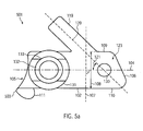
- Fig. 5a shows a schematic view of a plate 501 of another embodiment, in which instead of a cylindrically curved portion, a curved portion 503 is provided with an anticlastic shape.
- the further features of the plate 501 may correspond to those of the plate 101.
- a detail view of the curved portion 503 is shown in FIG Fig. 5b shown. For the sake of clarity, in Fig. 5b some parts of the plate 501 omitted.
- the curved portion 503 has a surface portion 520.
- the surface portion 520 is located on a side of the curved portion 503, which faces away from the curved portion 503 side 106 of the plate 501.
- the surface portion 520 is thus, if the plate 501, as in Fig. 2a, 2b and 5c
- the surface portion 520 may contact the patient's vertebra while the side of the curved portion 503 opposite the surface portion 520 faces away from the bone.
- the surface portion 520 may, in some embodiments, extend across the entire width 108 of the plate 501 in the transverse direction 107. In other embodiments, a beveled or rounded portion may be provided adjacent the surface portion 520 at the edge of the curved portion 503 to make the plate 501 less sharp-edged. In some of these embodiments, the surface area 520 may extend over 90% or more of the width 108.
- reference numeral 512 denotes a point in the surface portion 520.
- the plane of a first main normal section 502 of the surface portion 520 in FIG Point 512 is designated by reference numeral 505.
- the reference numeral 508 denotes the plane of the second main normal section 521 at the point 520.
- the planes 505, 508 pass through the point 512, are perpendicular to each other, and are parallel to a surface normal 522 of the surface section 520 at the point 512.
- the first main normal section 502 is an intersection of the surface section 520 with the plane 505.
- a circle of curvature of the first main normal section 502 at the point 520 with the center 506 and the radius 507 is designated by the reference numeral 504.
- the circle of curvature 504 lies in the plane 505, contacts the first main normal section 502 at the point 520 and has a curvature which is equal to the curvature of the main normal section 502 at the point 520.
- the second main normal section 521 is an intersection curve of the surface section 520 with the plane 508.
- a circle of curvature 511 of the second main normal section 521 at the point 512 lies in the plane 505, contacts the second main normal section 511 at the point 512, has a radius 510 and a center point 509.
- a curvature of the circle of curvature 511 is equal to the curvature of the second main normal section 521 at the point 512.
- the orientation of the planes 505, 508 is selected, in accordance with the mathematical definition of the principal normal sections, such that the radius of curvature 507 is a minimum of the radii of curvature of the intersections of the surface section 520 with all planes passing through the point 512 and parallel to the normal vector 522 , and the radius of curvature 510 is a maximum of all such radii of curvature.
- the radii of curvature of the cut lines are the radii of curvature at point 512.
- the midpoints 506, 509 lie on different sides of the surface portion 520.
- the center point 506 lies on the side of the curved portion 503 facing the curved portion 503 opposite side 106 of the plate 501.
- the center 509 lies on the side of the curved portion facing away from the side 106 of the plate opposite the curved portion 503.
- the surface portion 520 thus has a saddle shape that corresponds to the shape of the edge of the lamina of the human vertebral bone. Thereby, a better adaptation of the shape of the curved portion 503 to the shape of the edge of the lamina of a human vertebral bone can be achieved.
- the surface portion 520 may at least approximately have the shape of a hyperbolic paraboloid. In other embodiments, the surface portion 520 may be at least approximately in the shape of a hyperboloid of revolution. Between the surface portion 520 and the support surface 122 and / or between the surface portion 520 and the protrusions 111, 112 may be a transition region, so that there is a continuous transition between the shape of the surface portion 520 and the shape of the support surface 122 and the shape of the Projections 111, 112 results.
- the normal direction of the plane 505 of the first main normal section 502 with the minimum radius of curvature 507 at the point 512 may be oblique to the longitudinal direction 104 at all points 512 in the surface section 520.
- the average angle of the normal 507 to the plane of the first main normal section 502, wherein the averaging over all points 512 in the surface section 520 is performed may have a value in the range of 95 to 115 degrees, for example a value of 100 degrees.
- the angle between the normal 507 to the plane of the first main normal section 502 and the longitudinal direction 104 at one, several or all points 512 located midway between the longitudinal sides 109, 110 may be in the range of 95 to 115 degrees, for example, a value of 100 degrees.
- the axis of rotation with the longitudinal direction 104 may include an angle in the range of 95 to 115 degrees, for example, an angle of 100 degrees.
- the curved section having a cylindrical curvature described above is the direction of the normal to the plane of the main section having a minimum radius of curvature through a point of the cylindrical surface of the curved section parallel to the direction the curvature axis 117.
- the second main section is obtained in the case of a cylindrical surface an infinite radius of curvature.
- the curved portion 103, 503 may be bent at an angle of approximately 180 degrees to the support portion 102, and the protrusions 111, 112 may be approximately straight so that they lie in a plane approximately parallel to a plane through the Longitudinal direction 104 and the transverse direction 107 is.
- the curved portion 103, 503 may be bent at an angle of less than 180 degrees to the support portion 102, such that the portions 114, 116 of the protrusions facing the curved portion 103, 503 extend to the plane through the longitudinal direction 104 and the transverse direction 107 are inclined.
- the protrusions 111, 112 may be straight so that the entire protrusions 111, 112 are inclined to the plane through the longitudinal direction 104 and the transverse direction 107.
- the portions 114, 116 facing the curved portion 103, 503 may be curved in the same direction as the curved portion 103 or, in the case of an anticlastic shape of the curved portion 503, continue the anticlastic shape of the curved portion 503.
- the curved portion 103, 503 is bent at an angle of approximately 90 degrees to the support portion 102 and the curved portion 103 facing portions 114, 116 are also bent by an angle of approximately 90 degrees to the support portion 102, so that the parts 113, 115 facing away from the curved portion 103 are approximately parallel to the plane through the longitudinal direction 104 and the transverse direction 107.
- the support section 102 may have an extension 119 on one of the longitudinal sides 109, 110, for example the longitudinal side 109.
- the extension 119 may extend along a direction 120 that forms an angle with the longitudinal direction 104, which in FIG Fig. 1b designated by reference numeral 121.
- the angle 121 may have a value less than 90 degrees, so that the extension 119 is oblique to the longitudinal direction 104.
- the extension 119 is thus inclined toward the curved portion 103, 503 and inclined away from the side 106 of the plate 101, which is opposite to the curved portion 103, 503.
- the axis of curvature 117 may extend obliquely to the longitudinal direction 104 and the transverse direction 107.
- the axis of curvature 117 may be inclined toward the extension 119, with the angle 118 between the axis of curvature 117 and the longitudinal direction 104 located on the side of the longitudinal direction 104 remote from the extension 119, as described above, being greater takes as 90 degrees.
- the side 106 of the plate 101, 501 opposite the curved portion 103 may also be inclined toward the extension 119 such that the support portion 102 has a trapezoidal shape.
- the longitudinal side 109, on which the extension 119 is located, is shorter than the projection 119 opposite longitudinal side 110th
- the angle 121 may have a value in the range of 30 to 60 degrees, for example, a value of about 45 degrees.
- the extension 119 is adapted to be suspended in the spinous process of the vertebra of the patient to which the fastener 100 is attached.
- the extension 119 is deformable.
- the appendage 119 may be bent with a tool, such as forceps, into a hook-shaped shape adapted to the individual anatomy of the patient.
- the extension 119 may initially be substantially straight. In other embodiments, the extension 119 may already be hook-shaped in the manufacture of the fastener 100.
- the present invention is not limited to embodiments in which the support portion 102 has an extension 119.
- the extension 119 may be omitted.
- the support portion 102 may have a trapezoidal shape, wherein the axis of curvature 117 and the opposite side 106 include an acute angle, so that one of the two longitudinal sides 109, 110, for example, the longitudinal side 109, is shorter than the other.
- the holding member 124 may have a curved portion 125 similar to the curved portion 103, 503 of the plate 101, 501 and protrusions 126, 127 similar to the protrusions 112, 113. Thereby, the holding member 124 in the lamina of the vortex, on which the fastener 100 is mounted, are hung, and although at an edge of the lamina, which is opposite to that edge on which the curved portion 103, 503 is suspended.
- a portion of the lamina may be suspended after being interposed between the protrusions 126, 127 and a portion of the support member disposed on the opposite side of the curved portion 125 from the protrusions 126, 127 and / or between the protrusions 126, 127 and a part of the support portion 102 near the side 106.
- the fastener When the holding member 124 is connected to the plate 101, 501, e.g. by screwing by means of the screw 129, the fastener can, by the above-described shape of the plate 101, 501 and the holding member 124, obtain a staple-shaped shape suitable for enclosing the lamina of a vertebra. Thereby, a primarily stable attachment of the fastener 100 and connected to the fastener 100 further parts of an implant can be improved. An accidental slipping or slipping out of the fastener 100 from the lamina can be avoided so well.
- the present invention is not limited to embodiments in which the holding member 124 is present.
- the retaining member 124 may be omitted.
- the opening 130 of the plate may also be omitted.
- the opening 130 may be present to facilitate attachment of the retaining member 124 as needed.
- the support surface 122 of the support portion 102 may have a concave shape. Thereby, an adaptation of the shape of the support surface 122 to the anatomical shape of the lamina can be achieved, which allows an enlargement of the contact surface of the fastening element 100 with the lamina.
- Fig. 4 shows a schematic perspective view of a vortex 301.
- the vortex 301 is visible from another perspective.
- an intervertebral disc Between the vertebra 301 and an adjacent vertebra 302 is an intervertebral disc.
- the lamina 310 can be seen.
- the caudal side of vortex 301 is in the Fig. 4 arranged below, the cranial side of the Vertebra 301 above.
- the curvature of the surface of the lamina 310 is schematically represented by curves 401, 402, 403, 404 each extending on the surface of the lamina 301 and lying in a plane intersecting the vortex 301.
- the lamina 310 has, near the cranial edge 408, a region 406 in which the surface of the lamina 310 has a saddle-shaped form. As can be seen in the course of the curves 401 and 402 in the area 406, the surface of the lamina 310 in the direction in which the line 401 extends curved away from the viewer, while in the direction in which the line 402 extends, to the viewer is too curved.
- the lamina 310 has another area 407 in which its surface has a saddle-shaped shape, which can be seen in the course of the curves 401 and 403 in this area.
- region 405 in which the surface of the lamina 310 has a trough-shaped form.
- region 405 both the curve 401 and the curve 404 are curved toward the observer.
- the bearing surface 122 it is possible for the bearing surface 122 to rest on the surface of the lamina 310 both in the region of the depression 405 and in the saddle-shaped regions 406, 407, thereby increasing the contact surface between the fastening element 100 and the lamina 310 can be.
- FIGS. 2a and 2b show the plate 101, 501, wherein the plate 101, 501 in the view of Fig. 2a is shown from the same direction as in the Fig. 1b and in the view of Fig. 2b is shown from the same direction as in the Fig. 1d ,
- the plate 101, 501 in the Fig. 2a and 2b shown in a straightened state.
- the in the Fig. 1a . 1b and 1d shown shape of the plate 101 may from the in the Fig.
- the shape of the flap 501 shown can be obtained by additionally deforming the curved portion 503 such that on the side facing away from the side 106 a "recess" corresponding to the anticlastic shape receives. This can be done for example by hot forming. Alternatively, the anticlastic shape of the curved portion can also be produced by punching.
- the plate 101, 501 may have a width 108 in the range of 7 to 13 mm.
- a width in this area may correspond to the distance between the extensions of the spinous process 312 and the articular process 314, so that the attachment element 100 can be inserted between the articular process 314 and the spinous process 312.
- the width 108 may be adapted to the individual anatomy of the patient and to the vertebra to which the fastener 100 is to be attached. As the size of the vertebrae decreases in the cranial direction, the fastener 100 may have a greater width 108 when it is to be attached to a lumbar vertebra or lower thoracic vertebra than when attached to a vertebra in the upper chest or cervical vertebra should.
- the length 210 may be in the range of 10 to 25 mm, for example, about 22 or about 23 mm.
- the curved portion 103, 503 has a length 202 that can be measured from the beginning of the curved portion 103 on the side of the support portion 102 to the projection of the projections 111, 112.
- the length 202 may be in the range of 3 mm to 7 mm, for example about 5 mm.
- the above with reference to Fig. 5a . 5b described surface portion 520 may occupy 50% or more of the length of the curved portion 503. In the remainder of the curved portion, there may be a transition region in which the anticlastic shape merges into another, for example, cylindrical, curved shape. However, in some embodiments, the surface portion 520 may occupy the entire length of the curved portion 503.
- the curved section does not have to, as in Fig. 2a shown to be bounded by two substantially straight lines.
- the curved Section which is designated in these embodiments by the reference numeral 503 is provided with an anticlastic shape
- the curved portion 503 may be bounded by two straight lines, as in FIG Fig. 2a shown.
- the projections 111, 112 have a length 203 which can be measured from the projection of the respective projection 111, 112 to the tip of the projection 111, 112.
- the length of both projections 111, 112 may be the same.
- the length 203 of the protrusions 111, 112 may be in the range of 3 mm to 10 mm, for example about 5 mm or about 8 mm.
- a greater length 203 of the projections 111, 112 may allow a more stable attachment of the fastener 100 to the lamina. However, because the projections 111, 112 on the implanted fastener 100 are on the side of the lamina 310 facing the patient's spinal cord, the length 203 should be adjusted to maintain a safe distance from the spinal cord to prevent spinal cord injury.
- the projections 111, 112 may have a greater length when the attachment member 100 for suspending the curved portion 103, 503 in the caudal edge 409 is provided as if the fastener 100 is provided for suspending the curved portion 103 in the cranial edge 408.
- the length 203 may be about 5 mm, and the length 203 may be about 8 mm if the curved portion 103 is to be hooked into the caudal edge 409.
- the projections 111, 112 can be formed with truncated edges, for example with rounded edges. This further reduces the risk of injuring the patient's spinal cord upon insertion of the fastener 100.
- the extension 119 may have a length 204 in the range of 17 to 25 mm, for example a length of about 21 mm or about 20 mm and a width 205 in the range of 4 mm to 8 mm, for example a width of about 6 mm.
- a distance 206 between the curved portion 103, 503 side facing the extension 119 and the curved portion 103 may be in the range of about 1 mm to about 3 mm, for example, about 2 mm.
- Reference numeral 255 denotes a plane passing through portions of the support surface 122 adjacent to the curved portion 103, 503 and through portions of the support surface 122 on the side 106 of the plate 101, 501 facing the curved portion 103.
- the plane 255 may extend through the edge of the support surface 122 on the side 106 and through a point of the support surface immediately adjacent to the curved portion 103, 503.
- the support surface 122 Due to the convex shape of the support surface 122 are parts of the support surface not in the plane 255, but are at a distance to the plane.
- the distance of a point on the support surface 122 from the plane can be measured in a direction perpendicular to the plane 255 direction.
- the support surface 122 includes one or more points spaced from the plane 255 that is greater than or equal to the distance of all other points of the support surface 122 from the plane 255.
- the distance of these points from the plane 255 will hereinafter be referred to as "maximum distance", and the points located at the maximum distance from the plane 255 will be referred to as "points of maximum distance”.
- Reference numeral 250 denotes a substantially flat portion of the support surface 122 which is substantially parallel to the plane 255.
- the portion 255 may be circular with a diameter 254.
- the diameter 254 may have a value in the range of 3 mm to 6 mm, for example a value of approximately 4 mm. Points on the support surface in part 250 are at a distance 257 from plane 255.
- the flat part 250 of the support surface 122 may be surrounded by a part 251 having a substantially conical shape. Points in the conical part 251 of Pad 122 are spaced apart from plane 255 which is less than the spacing of the dots in flat portion 250 of pad 122 from plane 255. Thus, the flat portion 250 of the support surface 122 forms a set of points maximum distance from the plane 255.
- the bearing surface 122 can lie substantially in the plane 255, so that the bearing surface in the vicinity of the corners formed by the sides 105, 106 and the longitudinal sides 109, 110 is substantially flat. In the middle of the sides 105, 106, the conical region 122 can extend to the edge of the support section 102 and intersect the plane 255 there.
- the conical part 251 of the support surface 122 does not have to, as in Fig. 2b shown extending from the edge of the flat portion 250 to the edge of the support portion 102 on the sides 105, 106 of the plate 101, 501.
- the conical portion 251 may annularly enclose the flat portion 250. Outside the conical part 251, the support surface 122 may lie substantially in the plane 255.
- the flat portion 250 and the conical portion 251 may at least partially rest in the trough-shaped area 405 of the lamina 310. Thereby, the contact area between the lamina 310 and the plate 101 can be increased.
- the at least partial support of the flat part 250 and / or the conical part can be achieved with constant dimensions in a certain range of dimensions of the vortex, so that the same fastening elements 100 can be used on different sized vertebrae. It is therefore possible to provide a plurality of differently dimensioned vertebrae with a relatively small selection of differently dimensioned fasteners, thereby enabling economical production of the fasteners.
- the present invention is not limited to embodiments in which the bearing surface 122 has the shape described above.
- the support surface 122 may at least partially have a spherical, hyperboloidal, paraboloidal or ellipsoidal shape.
- the distance 257 of the maximum distance points from the plane 255 may have a value in the range of 1 mm to 2 mm, for example, a value of about 1.5 mm.
- a distance between the center of the flat portion 250 and the side 106 may have a value in the range of about 7 to about 11 mm, for example, a value of about 8 mm or about 10 mm.
- the connector 131 may be disposed opposite at least one of the maximum distance points from the plane 255.
- the holding member 130 may be disposed opposite to the flat portion 250 of the support surface 122.
- the top surface 123 may also have a convex shape.
- the top surface 123 may have one or more maximum distance points from a plane 256 that extends through portions of the top surface 123 adjacent to the curved portion 103 and through portions of the top surface 123 on the side 106 that faces the curved portion 103, 503.
- the maximum distance points may have a distance 258 in the range of 3 to 5 mm, for example a distance of approximately 4 mm, from the plane 256.
- the top surface 123 may include a substantially flat portion 252 that is parallel to the plane 256 and spaced therefrom 258, and a generally tapered portion 253 that surrounds the portion 252.
- the flat part 252 of the top surface 123 may be opposite to the flat part 250 of the support surface 122.
- the diameter of the flat parts 250, 252 may be approximately equal.
- the holding member 130 may be disposed in the flat part 252 so as to be connected to a maximum thickness portion of the plate. Thereby, the rigidity of the fastener 100 can be improved.
- An spinal deformity correction implant according to the present invention may comprise two or more fasteners having the features of the fastener 100 described above.
- the shape of the fasteners can be adjusted depending on the nature of the attachment of the implant to the spinal column of the patient.
- the shape of the fastener 100 may differ depending on whether it is for hooking the curved portion 103, 503 into the cranial (upper) edge 408 the lamina 310 or for hanging the curved portion 103, 503 in the caudale (lower) edge 409 of the lamina 310 is designed.
- the caudal edge fastener may have a greater width 108 than the cranial edge fastener.
- the caudal edge fastener may have a width of 10 or 12 mm, and the crain edge fastener may have a width of 8 or 10 mm.
- the protrusions 111, 112 of the caudal edge fastener may have a greater length.
- the cranial edge fastener may be formed with the appendage 119 for attachment to the spinous process of the patient's vertebra, while in the caudal edge fastener, the appendage 119 may be omitted.
- different fasteners may be provided for attachment to the left or right lamina, with the left side fasteners being mirror symmetric to those for the right side.
- the shorter longitudinal side 109 and the extension 119 are attached adjacent the spinous process of the vertebra.
- the longer side 110 is then next to one of the transverse processes of the vortex.
- Fig. 3a shows a schematic representation of a portion of a spine 300 of a patient.
- Fig. 3a shows the caudal direction to the right and the cranial direction points to the left.
- Spine 300 includes vertebrae 301, 302, 303, 304, 305, between which intervertebral discs 306, 307, 308, 309 are located.
- the vertebra 301 comprises a vertebral body 311, a spinous process 312 and transverse processes 313, 314. Between the transverse process 313 and the spinous process 312 is a lamina 310. Another lamina is located between the spinous process 312 and the transverse process 314.
- the shape of the lamina 310 was referring to above Fig. 4 explained in more detail.
- the vertebrae 302 to 305 have a similar shape as the vertebra 301, but are slightly larger because they are further caudal.
- the portion of the spine 300 that is to be corrected and / or stabilized with the aid of the implant for example the vertebrae 301 to 304, is exposed. This can be done with the aid of the techniques known to those skilled in the art.
- Fig. 3b shows the in Fig. 3a shown portion of the spine 300 at a later stage of implantation.
- a plate 101a of a first fastening element 100a is mounted on the lamina 310 of the vertebra 301 , which is connected to a first connecting element 131a.
- Attached to the lamina of the vortex 304 is the plate 101b of a second fastener 100b of the present invention connected to a second connector 131b.
- the fasteners 100a, 100b may have features corresponding to those described above with respect to FIGS Fig. 1a to 1d . 2a, 2b and 5a, 5b have been described.
- the plates 101a, 101b may have the features of the above with reference to FIG Fig. 1a to 1d described plate 101, or the features of the above with reference to Fig. 5a . 5b have described plate 501.
- the curved portions indicated by the reference numerals 103a, 103b may be cylindrically curved portions or anticlastic curved portions.
- the curved portion 103a of the plate 101a of the first attachment member 100a is hung in the cranial edge of the lamina 310 of the vertebra 301, and the curved portion 103b of the plate 101b of the second attachment member 100b is hung in the caudal edge of the lamina of the vertebra 304.
- a severing of the yellow band is not required. Instead, the protrusions of the fasteners 100a, 100b (in FIG Fig. 3b not visible) are clamped in the yellow band.
- the curved portions 103a, 103b may be sandwiched between the base of the spinous processes of the vertebrae 301, 304 and the medial edge of the articular processes of the vertebrae 302, 304.
- the first fastening element 100a has an extension 119a, which is suspended in the spinous process 312 of the vertebra 301.
- the Extension 119a initially be substantially straight (as in Fig. 1a to 2b shown) and are brought into a hook-shaped form during the operation by bending with the help of a pair of pliers. Thereby, an adaptation of the shape of the extension 119 to the individual anatomy of the patient can be achieved.
- the second fastener 100b does not include any extension in this embodiment.
- Fig. 3c shows the spine 300 at a later stage of implantation.
- a retaining element 124a of the first fastening element is hooked into the caudal edge of the lamina 310 of the vertebra 301 and connected by a screw 129a to the plate 101a of the first fastening element 100a.
- a holding element 124b is suspended in the cranial edge of the lamina of the vertebra 304 and connected by means of a screw 129b with the plate 101b of the second fastening element.
- one or both of the support members 124a, 124b may be omitted.
- the retaining members 124a, 124b may also be used as needed when the degree of primary stability achieved without the retaining members 124a, 124b is considered insufficient.
- the holding members 124a, 124b may be omitted.
- the correcting and stabilizing function of the fastening elements 100a, 100b can also be achieved without the holding plates 124a, 124b, while the holding elements 124a, 124b can be used as aids for intraoperative manipulation.
- Fig. 3d shows the spine 300 in a further stage of implantation.
- the spine 300 is aligned by moving the patient to a desired position.
- the portion of the spine 300 between the vertebrae 301 and 304 by inserting a connecting rod 380 in the connecting elements 130a, 130b and fixing the connecting rod 380 in the connecting elements 130a, 130b, for example by means of screws 381, 382, in the thread of the Connecting elements 130a, 130b are screwed, stabilized in the desired position and fixed.
- the retaining elements 124a, 124b may be removed after fixing the connecting rod 380. In other embodiments, however, they may remain in the body of the patient.
Landscapes
- Health & Medical Sciences (AREA)
- Orthopedic Medicine & Surgery (AREA)
- Life Sciences & Earth Sciences (AREA)
- Neurology (AREA)
- Surgery (AREA)
- Heart & Thoracic Surgery (AREA)
- Engineering & Computer Science (AREA)
- Biomedical Technology (AREA)
- Nuclear Medicine, Radiotherapy & Molecular Imaging (AREA)
- Medical Informatics (AREA)
- Molecular Biology (AREA)
- Animal Behavior & Ethology (AREA)
- General Health & Medical Sciences (AREA)
- Public Health (AREA)
- Veterinary Medicine (AREA)
- Prostheses (AREA)
- Surgical Instruments (AREA)
Applications Claiming Priority (1)
| Application Number | Priority Date | Filing Date | Title |
|---|---|---|---|
| DE102008035093.1A DE102008035093B4 (de) | 2008-07-28 | 2008-07-28 | Befestigungselement zur Befestigung eines Implantats an einer Lamina eines Wirbels und Implantat zur Korrektur einer Wirbelsäulendeformität |
Publications (2)
| Publication Number | Publication Date |
|---|---|
| EP2149341A2 true EP2149341A2 (fr) | 2010-02-03 |
| EP2149341A3 EP2149341A3 (fr) | 2010-03-31 |
Family
ID=41258651
Family Applications (1)
| Application Number | Title | Priority Date | Filing Date |
|---|---|---|---|
| EP09009747A Withdrawn EP2149341A3 (fr) | 2008-07-28 | 2009-07-28 | Elément de fixation destiné à la fixation d'un implant sur une lame d'une vertèbre |
Country Status (2)
| Country | Link |
|---|---|
| EP (1) | EP2149341A3 (fr) |
| DE (1) | DE102008035093B4 (fr) |
Cited By (3)
| Publication number | Priority date | Publication date | Assignee | Title |
|---|---|---|---|---|
| EP2675379A4 (fr) * | 2011-02-15 | 2016-10-12 | Glenn R Buttermann | Dispositif orthopédique segmentaire pour l'élongation spinale et le traitement de la scoliose |
| US11510709B2 (en) * | 2019-02-11 | 2022-11-29 | Carl P. Giordano | Methods and apparatus for treating spondylolysis |
| US20230240727A1 (en) * | 2022-01-28 | 2023-08-03 | Carl P. Giordano | Methods and apparatus for treating spondylolysis |
Citations (2)
| Publication number | Priority date | Publication date | Assignee | Title |
|---|---|---|---|---|
| WO1994017746A1 (fr) | 1993-02-05 | 1994-08-18 | Synthes Ag, Chur | Crochet utilise pour traiter des deformations de la colonne vertebrale |
| DE69932444T2 (de) | 1998-09-25 | 2007-03-08 | Perumala Corp., Brownsville | Mehrachsige verbindungen zwischen wirbelsäulenstützen und schrauben |
Family Cites Families (6)
| Publication number | Priority date | Publication date | Assignee | Title |
|---|---|---|---|---|
| US5415659A (en) * | 1993-12-01 | 1995-05-16 | Amei Technologies Inc. | Spinal fixation system and pedicle clamp |
| US5507747A (en) * | 1994-03-09 | 1996-04-16 | Yuan; Hansen A. | Vertebral fixation device |
| JP2003038507A (ja) * | 2001-08-01 | 2003-02-12 | Showa Ika Kohgyo Co Ltd | 骨接合具用インプラント |
| US20050080414A1 (en) * | 2003-10-14 | 2005-04-14 | Keyer Thomas R. | Spinal fixation hooks and method of spinal fixation |
| US8177823B2 (en) * | 2005-06-30 | 2012-05-15 | Depuy Spine Sarl | Orthopedic clamping hook assembly |
| US8317845B2 (en) * | 2007-01-19 | 2012-11-27 | Alexa Medical, Llc | Screw and method of use |
-
2008
- 2008-07-28 DE DE102008035093.1A patent/DE102008035093B4/de not_active Expired - Fee Related
-
2009
- 2009-07-28 EP EP09009747A patent/EP2149341A3/fr not_active Withdrawn
Patent Citations (2)
| Publication number | Priority date | Publication date | Assignee | Title |
|---|---|---|---|---|
| WO1994017746A1 (fr) | 1993-02-05 | 1994-08-18 | Synthes Ag, Chur | Crochet utilise pour traiter des deformations de la colonne vertebrale |
| DE69932444T2 (de) | 1998-09-25 | 2007-03-08 | Perumala Corp., Brownsville | Mehrachsige verbindungen zwischen wirbelsäulenstützen und schrauben |
Non-Patent Citations (2)
| Title |
|---|
| "Campbell's Operative Orthopedics", 2003, MOSBY |
| DAVID S. BRADFORD: "Moe's textboook of scoliosis and other spinal deformities", 1978, W.B. SAUNDERS COMPANY |
Cited By (5)
| Publication number | Priority date | Publication date | Assignee | Title |
|---|---|---|---|---|
| EP2675379A4 (fr) * | 2011-02-15 | 2016-10-12 | Glenn R Buttermann | Dispositif orthopédique segmentaire pour l'élongation spinale et le traitement de la scoliose |
| US11510709B2 (en) * | 2019-02-11 | 2022-11-29 | Carl P. Giordano | Methods and apparatus for treating spondylolysis |
| US11819250B2 (en) | 2019-02-11 | 2023-11-21 | Carl P. Giordano | Methods and apparatus for treating spondylolysis |
| US20230240727A1 (en) * | 2022-01-28 | 2023-08-03 | Carl P. Giordano | Methods and apparatus for treating spondylolysis |
| US11918259B2 (en) * | 2022-01-28 | 2024-03-05 | Carl P. Giordano | Methods and apparatus for treating spondylolysis |
Also Published As
| Publication number | Publication date |
|---|---|
| EP2149341A3 (fr) | 2010-03-31 |
| DE102008035093A1 (de) | 2010-02-18 |
| DE102008035093B4 (de) | 2016-01-14 |
Similar Documents
| Publication | Publication Date | Title |
|---|---|---|
| DE60014462T2 (de) | Wirbelsäulenfixationssystem | |
| US5951553A (en) | Methods and apparatus for fusionless treatment of spinal deformities | |
| DE69325023T2 (de) | Instrumentation zur segmentären rippenabstützung | |
| US6843790B2 (en) | Anatomic posterior lumbar plate | |
| DE69314334T2 (de) | Vorrichtung zur osteosynthese von rückenwirbeln | |
| US6645207B2 (en) | Method and apparatus for dynamized spinal stabilization | |
| US6623484B2 (en) | Methods and apparatus for fusionless treatment of spinal deformities | |
| EP2077783B1 (fr) | Raccord à tige centrale et tige en t | |
| DE69228319T2 (de) | Rückgrathaken | |
| US12127947B2 (en) | Lamina plate assembly | |
| DE112017003415T5 (de) | Dornfortsatz-laminaklemmvorrichtung | |
| DE112013003051T5 (de) | Verfahren und Vorrichtung für die Behandlung von Skoliose | |
| DE102008035093B4 (de) | Befestigungselement zur Befestigung eines Implantats an einer Lamina eines Wirbels und Implantat zur Korrektur einer Wirbelsäulendeformität | |
| EP3962381B1 (fr) | Dispositifs de traitement de fractures de stress vertébrales | |
| DE69332170T2 (de) | Gerät zur behandlung von thoraxdeformierungen wie skoliose | |
| WO2008061802A1 (fr) | Dispositif de fixation orthopédique et dispositif de correction de déformation de colonne vertébrale | |
| EP1635721B1 (fr) | Pinces orthopediques | |
| WO2003096914A1 (fr) | Dispositif d'ajustement d'une colonne vertebrale humaine ou animale et element de fixation prevu a cet effet | |
| EP3104793B1 (fr) | Système de fusion d'accès minimal cervical | |
| EP2036510B1 (fr) | Dispositif de correction de déformations cyphotiques de la colonne vertébrale |
Legal Events
| Date | Code | Title | Description |
|---|---|---|---|
| PUAI | Public reference made under article 153(3) epc to a published international application that has entered the european phase |
Free format text: ORIGINAL CODE: 0009012 |
|
| AK | Designated contracting states |
Kind code of ref document: A2 Designated state(s): AT BE BG CH CY CZ DE DK EE ES FI FR GB GR HR HU IE IS IT LI LT LU LV MC MK MT NL NO PL PT RO SE SI SK SM TR |
|
| AX | Request for extension of the european patent |
Extension state: AL BA RS |
|
| PUAL | Search report despatched |
Free format text: ORIGINAL CODE: 0009013 |
|
| AK | Designated contracting states |
Kind code of ref document: A3 Designated state(s): AT BE BG CH CY CZ DE DK EE ES FI FR GB GR HR HU IE IS IT LI LT LU LV MC MK MT NL NO PL PT RO SE SI SK SM TR |
|
| AX | Request for extension of the european patent |
Extension state: AL BA RS |
|
| 17P | Request for examination filed |
Effective date: 20100930 |
|
| 17Q | First examination report despatched |
Effective date: 20110620 |
|
| STAA | Information on the status of an ep patent application or granted ep patent |
Free format text: STATUS: THE APPLICATION IS DEEMED TO BE WITHDRAWN |
|
| 18D | Application deemed to be withdrawn |
Effective date: 20111231 |