EP2149342B1 - Système électrochirurgical polyphasé - Google Patents
Système électrochirurgical polyphasé Download PDFInfo
- Publication number
- EP2149342B1 EP2149342B1 EP09009860.9A EP09009860A EP2149342B1 EP 2149342 B1 EP2149342 B1 EP 2149342B1 EP 09009860 A EP09009860 A EP 09009860A EP 2149342 B1 EP2149342 B1 EP 2149342B1
- Authority
- EP
- European Patent Office
- Prior art keywords
- polyphase
- electrosurgical system
- phase
- electrodes
- electrosurgical
- Prior art date
- Legal status (The legal status is an assumption and is not a legal conclusion. Google has not performed a legal analysis and makes no representation as to the accuracy of the status listed.)
- Not-in-force
Links
Images




Classifications
-
- A—HUMAN NECESSITIES
- A61—MEDICAL OR VETERINARY SCIENCE; HYGIENE
- A61B—DIAGNOSIS; SURGERY; IDENTIFICATION
- A61B18/00—Surgical instruments, devices or methods for transferring non-mechanical forms of energy to or from the body
- A61B18/04—Surgical instruments, devices or methods for transferring non-mechanical forms of energy to or from the body by heating
- A61B18/12—Surgical instruments, devices or methods for transferring non-mechanical forms of energy to or from the body by heating by passing a current through the tissue to be heated, e.g. high-frequency current
- A61B18/1206—Generators therefor
-
- A—HUMAN NECESSITIES
- A61—MEDICAL OR VETERINARY SCIENCE; HYGIENE
- A61B—DIAGNOSIS; SURGERY; IDENTIFICATION
- A61B18/00—Surgical instruments, devices or methods for transferring non-mechanical forms of energy to or from the body
- A61B2018/00636—Sensing and controlling the application of energy
- A61B2018/00642—Sensing and controlling the application of energy with feedback, i.e. closed loop control
- A61B2018/00654—Sensing and controlling the application of energy with feedback, i.e. closed loop control with individual control of each of a plurality of energy emitting elements
-
- A—HUMAN NECESSITIES
- A61—MEDICAL OR VETERINARY SCIENCE; HYGIENE
- A61B—DIAGNOSIS; SURGERY; IDENTIFICATION
- A61B18/00—Surgical instruments, devices or methods for transferring non-mechanical forms of energy to or from the body
- A61B2018/00636—Sensing and controlling the application of energy
- A61B2018/00684—Sensing and controlling the application of energy using lookup tables
-
- A—HUMAN NECESSITIES
- A61—MEDICAL OR VETERINARY SCIENCE; HYGIENE
- A61B—DIAGNOSIS; SURGERY; IDENTIFICATION
- A61B18/00—Surgical instruments, devices or methods for transferring non-mechanical forms of energy to or from the body
- A61B2018/00636—Sensing and controlling the application of energy
- A61B2018/00696—Controlled or regulated parameters
- A61B2018/00732—Frequency
-
- A—HUMAN NECESSITIES
- A61—MEDICAL OR VETERINARY SCIENCE; HYGIENE
- A61B—DIAGNOSIS; SURGERY; IDENTIFICATION
- A61B18/00—Surgical instruments, devices or methods for transferring non-mechanical forms of energy to or from the body
- A61B2018/00636—Sensing and controlling the application of energy
- A61B2018/00696—Controlled or regulated parameters
- A61B2018/0075—Phase
-
- A—HUMAN NECESSITIES
- A61—MEDICAL OR VETERINARY SCIENCE; HYGIENE
- A61B—DIAGNOSIS; SURGERY; IDENTIFICATION
- A61B18/00—Surgical instruments, devices or methods for transferring non-mechanical forms of energy to or from the body
- A61B2018/00636—Sensing and controlling the application of energy
- A61B2018/00773—Sensed parameters
- A61B2018/00875—Resistance or impedance
-
- A—HUMAN NECESSITIES
- A61—MEDICAL OR VETERINARY SCIENCE; HYGIENE
- A61B—DIAGNOSIS; SURGERY; IDENTIFICATION
- A61B18/00—Surgical instruments, devices or methods for transferring non-mechanical forms of energy to or from the body
- A61B18/04—Surgical instruments, devices or methods for transferring non-mechanical forms of energy to or from the body by heating
- A61B18/12—Surgical instruments, devices or methods for transferring non-mechanical forms of energy to or from the body by heating by passing a current through the tissue to be heated, e.g. high-frequency current
- A61B18/1206—Generators therefor
- A61B2018/128—Generators therefor generating two or more frequencies
-
- A—HUMAN NECESSITIES
- A61—MEDICAL OR VETERINARY SCIENCE; HYGIENE
- A61B—DIAGNOSIS; SURGERY; IDENTIFICATION
- A61B18/00—Surgical instruments, devices or methods for transferring non-mechanical forms of energy to or from the body
- A61B18/04—Surgical instruments, devices or methods for transferring non-mechanical forms of energy to or from the body by heating
- A61B18/12—Surgical instruments, devices or methods for transferring non-mechanical forms of energy to or from the body by heating by passing a current through the tissue to be heated, e.g. high-frequency current
- A61B18/14—Probes or electrodes therefor
- A61B2018/1405—Electrodes having a specific shape
- A61B2018/1425—Needle
- A61B2018/143—Needle multiple needles
Definitions
- the present disclosure relates to electrosurgical instruments for open, percutaneous, endoscopic, or laparoscopic surgical procedures. More particularly, the present disclosure relates to a radiofrequency tissue ablation system having multiple, independently-phased electrodes for providing rapid energy delivery and improved ablation control.
- RF electrodes e.g., probes, resistive heating elements, and the like
- the RF electrodes can further include an exposed conductive tip portion and an insulated portion.
- the RF electrodes can also include a method of internal cooling, such as the RF electrodes shown and described in U.S. Patent Nos. 6,506,189 entitled "COOL-TIP ELECTRODE THERMOSURGERY SYSTEM” issued to Rittman, III et al., on Jan.
- RF electrode when the RF electrode is connected to an external source of radiofrequency power, e.g., an electrosurgical generator (device used to generate therapeutic energy such as radiofrequency, microwave, or ultrasonic), and current is delivered to the RF electrode, heating of tissue occurs near and around the exposed conductive tip portion thereof, whereby therapeutic changes in the target tissue, near the conductive tip, are created by the elevation of temperature of the tissue.
- an electrosurgical generator device used to generate therapeutic energy such as radiofrequency, microwave, or ultrasonic
- multiple electrodes may be inserted into the body in an array to enlarge ablation volumes.
- arrays of high frequency electrodes are inserted into tumors.
- the electrodes are typically placed in a dispersed fashion throughout the tumor volume to cover the tumor volume with uniform heat.
- the electrodes are arranged in a delta (i.e., triangular) configuration.
- the multiple electrodes may be activated simultaneously or sequentially with high frequency energy so that each electrode heats the surrounding tissue. Simultaneous activation allows maximum energy to the applied to the tissue, but may also have drawbacks.
- US 4785829 is concerned with an apparatus of hyper thermic treatment.
- US 5383917 concerned with a device for multi-phase radio-frequency ablation.
- US2006/015095 discloses apparatus for applying a high frequency current for thermal sclerosis of body tissue, includes an electrode array with at least three active electrodes which can be introduced into body tissue, a high frequency generator for producing a high frequency voltage, which generator is to be switchably connected to one or more of the electrodes, and a measuring device for measuring the impedance or the ohmic resistance of the tissue between all or selected active electrodes.
- the application apparatus further includes a selector device which is connected to the measuring device and adapted to select a sub-array including at least two active electrodes from the electrode array on the basis of the measured impedance or the ohmic resistance.
- a control device which is connected to the selector device and which is adapted to apply the high frequency voltage to the active electrodes of the selected sub-array in such a way that a high frequency current flows between them through the body tissue.
- imped-ance and in particular ohmic resistance as volume information about the tissue properties represents a measurement in respect of advance of the sclerosing effect
- impedance or active resistance measurement is suitable for establishing differing degrees of sclerosing in the region of the tissue to be sclerosed.
- EP 0833592 discloses An electrosurgical generator is disclosed that includes an exit spark control system. A basis for controlling the exit spark is to make temporary adjustments to the operation of the electrosurgical generator whenever conditions are likely for an exit spark to occur. The adjustments include momentarily shutting off the output of the electrosurgical generator and then temporarily changing the driving frequency of the output stage of the electrosurgical generator in order to reduce the gain of the output stage.
- a polyphase electrosurgical system comprising: a controller; a generator module operably coupled to the controller, the generator module configured to generate three radiofrequency signals having a phase offset therebetween and to provide the three radiofrequency signals to respective outputs; an electrosurgical instrument having three electrodes disposed in spaced relation, the electrodes operably coupled to the respective outputs of the generator module corresponding to the three radiofrequency signals; and a sensor in communication with at least one electrode for sensing .
- a tissue impedance the sensor operatively coupled to the controller, wherein the controller is configured to vary the frequency of one or more of the three radiofrequency signals in response ⁇ to the tissue impedance, and by an actuator operably coupled to the controller for activating the generator module.
- a polyphase RF generator having the capability of generating a plurality of independent RF signals.
- the frequency and phase of each RF signal is variable.
- the amplitude may be varied.
- the RF signals may be characterized by a substantially sinusoidal waveform, or may alternatively exhibit non-sinusoidal characteristics.
- Each independent signal are operably coupled to a corresponding electrode of the surgical instrument.
- a polyphase RF generator is configured to generate three RF signals having a phase offset, preferably about 120° therebetween, i.e., a three-phase configuration.
- phase 1 may be a reference phase having 0° phase shift
- phase 2 vary from phase 1 by about 120°
- phase 3 may vary from phase 2 by about 120° and from phase 1 by about 240°.
- a system operating in accordance with the present disclosure may operate in a balanced, or tri-polar, mode wherein a return electrode current (i.e. neutral current), is about zero because the total energy between the phases flows substantially among and between the electrodes of the instrument.
- a system operating in accordance with the present disclosure may operate in an unbalanced state, which may cause current flow through a return electrode.
- vaporization a.k.a. "bubble steam”
- eschar may form at the operative site which may alter the impedance at one or more electrodes at the operative site, resulting in a change of energy transfer rate at the affected electrode(s).
- An unbalanced operating mode may also be achieved by altering the phase, amplitude, and/or frequency of at least one of the electro surgical waveforms which may be useful, for example, for tailoring the shape or direction of the ablation region in accordance with therapeutic requirements. Additionally or alternatively, altering the phase, amplitude, and/or frequency of at least one of the electrosurgical waveforms may be useful to adapt the delivery of energy into tissue in response to conditions at the operative site, such as vaporization or eschar.
- control system for use with a polyphase electrosurgical generator which generates electrosurgical waveforms for application to tissue.
- At least one impedance sensor module is included that is corresponding to the application of the electrosurgical waveforms to the tissue.
- the control system includes a controller configured to adjust the phase, and frequency of one or more of the electrosurgical waveforms.
- the controller adjusts frequency in response to a tissue impedance.
- a controller may be configured to adjust frequency in response to a user input. For example, frequency may be adjusted by the user. In embodiments, in addition to frequency, the amplitude may be varied.
- the polyphase RF signals may be advantageously generated by digital synthesis.
- a digitized representation of a desired output waveform which may be a sine wave, may be stored within the RF generator.
- the stored representation may be organized in lookup table form.
- the digitized representation may be converted into analog form via a digital-to-analog (D/A) converter.
- D/A digital-to-analog
- Each separately phased signal may be associated with a corresponding D/A converter.
- a single multiplexed D/A converter may be associated with each phased signal.
- the generator may be configured to include multiple pointers (i.e., an offset) to data points of the digitized waveform table corresponding to the desired phase offset between each polyphase signal.
- a sine wave may be represented in a lookup table having 3,600 data points (i.e., samples), each point corresponding to the amplitude of a sine wave in 0.1° increments. Assuming a three-phase signal having 120° between phases, a first phase would correspond to an offset of 0 samples, a second phase would correspond to an offset of 1200 samples, and a third phase would correspond to an offset of 2400 samples.
- the stored data points are then processed by the D/A converters at the corresponding rate and offset to generate polyphase signals having the desired frequency and phase angle.
- the amplitude of each polyphase signal may be adjusted by, for example, digital scaling or a variable gain output amplifier.
- the phase angle of a selected signal may be adjusted by varying the table offset associated with that phase. Continuing with the present example, changing the table offset by a single location causes a phase change of 0.1°. Finer adjustments of phase may be achieved by, for example, interpolation of table values, or by providing a table having a greater number of data points
- the ability to control the return path of electrosurgical energy provided by the electrode cluster may be accomplished by altering the frequency and optionally additionally the phase, and/or amplitude, relationship between the waveforms.
- RF energy will follow the path of least resistance (averaged over the three-dimensional volumetric pathway) between the electrode and return pad; there is no clear method to divert or alter the electrical current flow direction - that path is defined by the physiological parameters as the area is ablated.
- the current flows between the two electrodes and the surrounding normal tissue anatomy/physiology, as well as the ablation created, dictate the overall current pathway.
- the device may be operated in a balanced mode (each electrode offset 120° in phase) to direct energy equally between the electrodes, in an unbalanced mode to deliver more current between specific electrodes and partially to the return pad, or in a single-phase mode where all the electrodes operate in the same phase (like a typical monopolar mode) which will direct the current only to the return pad. Adjusting the relative phases and amplitudes of the multiphase system may provide a level of control to current flow paths and subsequent nenergy deposition.
- an altered phase relationship is fixed during activation of the electrodes, which may be useful to tailor the direction and shape of the ablation region in accordance with operative requirements.
- the controller may be configured to adjust phase, amplitude, and/or frequency in accordance with predetermined time-varying contours. For example, amplitude modulation may be applied to each phase in succession to induce a quasi-rotating energy delivery pattern.
- the phases of two adjacent electrodes may be brought into or out of coherence over a period of time to alter the ablation area. This timed phase shift may be performed in a one-shot, multi-shot, or repeating manner.
- the shift pattern may be staggered or alternating, so that, for example, when the cluster electrodes are activated the phase difference between two electrode may continually vary from about 120° to about 0° and back to about 120° at a predetermined rate.
- the phase, and frequency of each electrode is independently varied in according with predetermined patterns. Thus, by altering the relationships of phase, and frequency of each electrode with respect to the others, a variety of ablation effects may be achieved.
- proximal refers to the end of the apparatus that is closer to the user and the term “distal” refers to the end of the apparatus that is further from the user.
- distal refers to the end of the apparatus that is further from the user.
- a polyphase electrosurgical system 100 in accordance with an embodiment of the present disclosure includes a polyphase RF generator 110 that is operably coupled to an electrosurgical instrument 120.
- a cluster electrode array 130 is provided at distal end 121 of electrosurgical instrument 120 for delivering electrosurgical energy to tissue of a patient P.
- Polyphase RF generator 110 is operably coupled to an electrosurgical instrument 120 by a cable 115, which is a multi-conductor cable.
- Polyphase electrosurgical system 100 may optionally be configured with at least one return electrode 140 to provide a return path for electrosurgical energy to polyphase RF generator 110 via conductor 150 operably coupled therebetween.
- return electrode 140 may be positioned on the body of a patient at, for example, the leg, buttocks, or other medically-suitable location.
- aspects of a polyphase electrosurgical system in accordance with an embodiment of the present disclosure include an electrosurgical instrument 210 having a housing 211 adapted for use by a user for performing open, percutaneous, endoscopic, or laparoscopic surgical procedures.
- the distal end 212 of instrument 210 includes electrodes 221, 222, and 223 that may be operably and/or independently coupled to separate sources of electrosurgical energy provided by polyphase electrosurgical generator 260.
- Instrument 210 may additionally include at least one user interface element 230, which may be used to facilitate control of the generator 260.
- user interface element 230 may be a momentary pushbutton (e.g., push-on/release-off), toggle pushbutton (e.g., push-on/push-off) or sequence pushbutton (e.g., for stepping through alternative selections). Additionally, or alternatively, user interface element 230 may be a slide switch or continuously variable control, such as a potentiometer.
- momentary pushbutton e.g., push-on/release-off
- toggle pushbutton e.g., push-on/push-off
- sequence pushbutton e.g., for stepping through alternative selections
- user interface element 230 may be a slide switch or continuously variable control, such as a potentiometer.
- Instrument 210 is operably coupled to polyphase generator 260 by a cable 235.
- cable 235 may be detachably coupled to the instrument 210. Additionally, or alternatively, cable 235 may be detachably coupled to polyphase generator 260 via connector 237.
- a strain relief 236 may be included at the proximal end 213 of instrument 210.
- a return electrode pad 240 having a return electrode 245 incorporated therewith may be provided.
- Return electrode pad 240 may be operably coupled to polyphase generator 260 by a cable 250.
- cable 250 may be detachably coupled to the instrument 210 and, additionally or alternatively, cable 250 may be detachably coupled to polyphase generator 260 via connector 251.
- Return electrode pad 240 may additionally include a connector 246 configured to couple cable 250 thereto.
- Polyphase generator 260 may include at least one user input element 270, 275 and display element 265 to facilitate user interaction with the system.
- Display element 265 may be any suitable display device, including without limitation an LED display, an LCD display, a graphics display (e.g., flat panel), or an electromechanical indicator.
- Fig. 3 there is illustrated a block diagram of a polyphase electrosurgical generator system 300 in accordance with an embodiment of the present disclosure.
- the system 300 includes a controller module 310 that is operably coupled to a three-phase generator module 330. Additionally, controller module 310 may be operably coupled to a user interface module 320 and/or an activation control, such as a footswitch 315.
- the controller 310, user interface module 320, and/or generator module 330 may conveniently be arranged in a common housing 305.
- Generator module 330 provides three RF outputs 331,332, and 333, corresponding to phase 1, phase 2, and phase 3, respectively, of a polyphase electrosurgical signal.
- Each RF output 331, 332, and 333 is operably coupled to electrodes 351, 352, and 353 by conductors 341, 342, and 343, respectively. Electrodes 351, 352, and 353 are disposed within an instrument housing 350 configured to position electrode tips 356, 357, and 358, at or adjacent to the distal end thereof. Instrument housing 350 may be constructed from materials that may include electrically non-conductive material, and may by be configured to electrically insulate electrodes 351, 352, and 353 from each other and from non-targeted tissue.
- controller module 310 may receive a user input from user interface module 320.
- a user may select a frequency and optionally additionally an amplitude, , and/or phase relationship characterizing the desired electrosurgical signal.
- a user may select a static electrosurgical signal, e.g., one characterized by a continuous steady-state delivery of energy.
- the user may select a dynamically-changing signal, wherein at least one signal parameter changes on a temporal basis, for example without limitation, periodic modulation (e.g., pulse width modulation) and aperiodic modulation (e.g., altering a parameter in a predetermined or arbitrary manner over time).
- Controller module 310 receives an activation signal from an activation control, such as a footswitch 315 or an activation control included with the instrument housing 350 (not explicitly shown). Upon receipt of an activation signal, controller module causes generator module 330 to begin outputting a polyphase RF signal at output 331, 332, and 333. The polyphase energy is conducted via conductors 341, 342, and 343 to electrodes 351, 352, and 353 for performing an electrosurgical procedure, such as ablation, on tissue T.
- an activation control such as a footswitch 315 or an activation control included with the instrument housing 350 (not explicitly shown).
- controller module causes generator module 330 to begin outputting a polyphase RF signal at output 331, 332, and 333.
- the polyphase energy is conducted via conductors 341, 342, and 343 to electrodes 351, 352, and 353 for performing an electrosurgical procedure, such as ablation, on tissue T.
- embodiments of the disclosed polyphase electrosurgical system are envisioned that include a processor 410 that is operably coupled to at least one storage device 415.
- the storage device may be of any type of suitable storage device, including without limitation fixed and/or removable solid state memory devices (such as dynamic RAM, flash memory, or read-only memory), or disk drives (i.e., magnetic, magneto-optical, or optical drives).
- Storage device 415 may contain a waveform table 430 that includes a digitized waveform representation, and may contain a set of programmable instructions configured for execution by processor 410.
- Processor 410 is operably coupled to digital-to-analog (D/A) converters 441, 442, and 443 for converting a digital representation of a waveform into analog form.
- the outputs of D/A converters 441, 442, and 443 are operably coupled to output stages 451, 452, and 453, which collectively may form an energy module 450.
- Output stages 451 et seq. may be an amplifier for amplifying the output of D/A converters 441 et seq. to the power level required for electrosurgical procedures.
- Output stages 451 may include a low-pass filter.
- the gain of output stages 451 et seq. may be controlled by processor 410, by, for example without limitation, direct control of the output stage 451 et seq.
- Outputs of the output stages 451 et seq. are operably coupled to electrodes 471, 472, and 473 via conductors 461, 462, and 463 for delivering electrosurgical energy to the operative site.
- a return electrode 480 and corresponding return conductor 481 may be operably coupled to energy module 450.
- processor 410 may be operably coupled to a display device 420, a user interface 425, and at least one activation control 435 that may be, for example, a footswitch or a handswitch.
- Processor 410 may be configured to perform a set of programmable instructions for receiving inputs from user interface 425 and/or activation control 435, and for causing operational information to be displayed on display device 420.
- processor 410 may be configured to read waveform data from waveform table 430 and cause the waveform data to be converted into analog form by D/A converters 441 et seq.
- processor 410 may retrieve waveform data from waveform table 430 from three separate table locations.
- the offset between the separate table locations from which waveform data is retrieved may be the number of waveform samples corresponding to the desired phase difference, which, in the present example, is 120°.
- the phase difference among and between the individuals may thus be tailored by varying this offset.
- the rate at which waveform samples are read from waveform table 430 and consequently converted to analog form is in direct proportion to the desired frequency of the polyphase signal and the number of samples that represent a single period of the waveform.
- the 120 samples representing a single period of the electrosurgical polyphase signal must be read and converted in a 2 ⁇ s time interval, which correspond to a rate of 16.7ns per sample, or a sample frequency of 60mHz.
- the frequency of one or more individual polyphase signal may be adjusted by altering the rate at which waveform data is delivered to, and converted by, a D/A converter 441 et seq.
- the phase and amplitude relationships among and between the polyphase signals may be adjusted by, for example, processor 410 and/or energy module 450 to achieve a target return electrode 480 current.
- a target return electrode current may be a minimal or nearly zero current.
- a software algorithm (not explicitly shown) adapted to be executed by processor 410 receives an input corresponding to the return electrode 480 current. In response thereto, the algorithm may alter one or more of the phase and/or amplitude of a polyphase signal to minimize or nearly eliminate the return electrode 480 current.
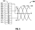
- phase 1 is generated by D/A converter 441 from samples beginning at sample 501
- phase 2 is generated by D/A converter 442 from samples initially indexed at 505
- phase 3 is generated by D/A converter 443 from samples indexed beginning at 509.
- Waveform table 530 may be organized as a circular table, that is, after the final sample is reached, an index "wraps" back to the beginning of the table, i.e., sample 501. In this manner a continuous waveform may be generated.
- the respective phase difference between individual polyphase signals may be altered by altering the table offset accordingly.
- table 530 may include greater or fewer samples, which may be scaled in any suitable manner, to correspond with, for example, the desired minimum phase angle resolution, or the amplitude resolution of D/A converter 441 et seq.
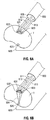
- FIG. 6A depicts a polyphase electrosurgical probe 600 having a three-phase electrode cluster that includes electrodes 611, 612, and 613 that are shown delivering polyphase electrosurgical energy to tissue T in a balanced mode.
- representative current flow lines 621, 622, and 623 in a balanced mode energy flows among and between three-phase electrode cluster formed by electrodes 611, 612, and 613, while negligible or no current flow exists between the three-phase electrode cluster and return electrode 625.
- the polyphase electrosurgical probe 600 is shown operating in an unbalanced mode, wherein energy flows among and between the three-phase electrode cluster as shown by representative current flow lines 631, 632, and 633 and between the electrode cluster and return electrode 625 as shown by representative current flow lines 634.
- a polyphase electrosurgical system accordance with the present disclosure having a three-phase topology may have a cluster electrode array that includes a triangular or delta electrode configuration 710.
- a three-phase electrosurgical system having six electrodes 720 and nine electrodes 730, respectively, is shown.
- Figs. 7D and 7E there is shown an exemplary configuration of a four-phase electrosurgical system having four electrodes 740 and eight electrodes 750, respectively, in accordance with the present disclosure.
- a polyphase cluster electrode 760 may be configured in a linear or lattice-type arrangement.
- the current paths between electrodes operating in a substantially balanced mode are depicted illustratively by 711, 721, 731, 741, 751, and 761, respectively.
- the phase relationship among and between multiple electrodes may be arbitrarily configured or patterned to tailor energy delivery patterns to achieve a particular ablation region shape.
Landscapes
- Health & Medical Sciences (AREA)
- Surgery (AREA)
- Engineering & Computer Science (AREA)
- Life Sciences & Earth Sciences (AREA)
- Biomedical Technology (AREA)
- Otolaryngology (AREA)
- Nuclear Medicine, Radiotherapy & Molecular Imaging (AREA)
- Plasma & Fusion (AREA)
- Physics & Mathematics (AREA)
- Heart & Thoracic Surgery (AREA)
- Medical Informatics (AREA)
- Molecular Biology (AREA)
- Animal Behavior & Ethology (AREA)
- General Health & Medical Sciences (AREA)
- Public Health (AREA)
- Veterinary Medicine (AREA)
- Surgical Instruments (AREA)
Claims (9)
- Système électrochirurgical polyphasé pour l'ablation de tissu comprenant :une unité de commande (310) ;un module de générateur polyphasé (330) couplé de manière fonctionnelle à l'unité de commande (310), le module de générateur (330) étant configuré pour générer trois signaux de radiofréquence indépendamment variables ayant un décalage de phase sélectionnable entre eux et pour fournir les trois signaux de radiofréquence aux sorties respectives (331, 332, 333) ;un instrument électrochirurgical ayant trois électrodes (356, 357, 358) disposées en relation espacée, les électrodes (356, 357, 358) étant couplées de manière fonctionnelle aux sorties respectives (331, 332, 333) du module de générateur correspondant aux trois signaux de radiofréquence ;un capteur en communication avec au moins une électrode pour détecter une impédance de tissu, le capteur étant couplé de manière fonctionnelle à l'unité de commande (310), dans lequel l'unité de commande (310) est configurée pour faire varier la fréquence d'un ou plusieurs des trois signaux de radiofréquence en réponse à l'impédance de tissu, etun actionneur couplé de manière fonctionnelle à l'unité de commande (310) pour activer le module de générateur (330) ;dans lequel les décalages de phase et les fréquences des trois signaux sont sélectionnables pour adapter des motifs de distribution d'énergie appliqués au tissu.
- Système électrochirurgical polyphasé selon la revendication 1, dans lequel le décalage de phase est sélectionné dans le groupe constitué par environ 120 degrés, environ 90 degrés, et dans la plage d'environ 1 degré à environ 180 degrés.
- Système électrochirurgical polyphasé selon la revendication 1 ou 2, comprenant en outre :au moins un convertisseur numérique-analogique (441, 442, 443),un dispositif de stockage (415) ayant une représentation numérisée d'une forme d'onde stockée à l'intérieur de celui-ci ;un processeur (410) couplé de manière fonctionnelle au convertisseur numérique-analogique (441, 442, 443) et au dispositif de stockage (415), le processeur (410) étant configuré pour exécuter un ensemble d'instructions programmables pour générer les trois signaux de radiofréquence.
- Système électrochirurgical polyphasé selon la revendication 3, comprenant en outre de multiples pointeurs vers des points de données du tableau de forme d'onde numérisé correspondant au décalage de phase entre les signaux de radiofréquence.
- Système électrochirurgical polyphasé selon la revendication 3 ou 4, dans lequel l'ensemble d'instructions programmables est configuré pour faire varier l'amplitude d'au moins un des signaux de radiofréquence.
- Système électrochirurgical polyphasé selon la revendication 3, 4, ou 5, dans lequel l'ensemble d'instructions programmables est configuré pour faire varier la fréquence d'au moins un des signaux de radiofréquence.
- Système électrochirurgical polyphasé selon l'une quelconque des revendications précédentes, comprenant en outre un module d'affichage (420) couplé de manière fonctionnelle à l'unité de commande (310) pour l'affichage de paramètres opérationnels.
- Système électrochirurgical polyphasé selon l'une quelconque des revendications précédentes, comprenant en outre une électrode de retour (140) couplée de manière fonctionnelle au module de générateur (330) pour la fourniture d'un trajet de retour pour au moins un des signaux de radiofréquence.
- Système électrochirurgical polyphasé selon l'une des revendications précédentes, dans lequel l'actionneur (315) est sélectionné dans le groupe constitué par un interrupteur à main et un interrupteur à pied.
Applications Claiming Priority (1)
| Application Number | Priority Date | Filing Date | Title |
|---|---|---|---|
| US12/184,556 US9700366B2 (en) | 2008-08-01 | 2008-08-01 | Polyphase electrosurgical system and method |
Publications (2)
| Publication Number | Publication Date |
|---|---|
| EP2149342A1 EP2149342A1 (fr) | 2010-02-03 |
| EP2149342B1 true EP2149342B1 (fr) | 2018-10-24 |
Family
ID=41376414
Family Applications (1)
| Application Number | Title | Priority Date | Filing Date |
|---|---|---|---|
| EP09009860.9A Not-in-force EP2149342B1 (fr) | 2008-08-01 | 2009-07-30 | Système électrochirurgical polyphasé |
Country Status (3)
| Country | Link |
|---|---|
| US (1) | US9700366B2 (fr) |
| EP (1) | EP2149342B1 (fr) |
| JP (1) | JP5596944B2 (fr) |
Cited By (1)
| Publication number | Priority date | Publication date | Assignee | Title |
|---|---|---|---|---|
| EP3678569A1 (fr) * | 2017-09-07 | 2020-07-15 | Biosense Webster (Israel) Ltd. | Génération et détection de phase variable pour ablation par radiofréquence (rf) |
Families Citing this family (81)
| Publication number | Priority date | Publication date | Assignee | Title |
|---|---|---|---|---|
| US7137980B2 (en) | 1998-10-23 | 2006-11-21 | Sherwood Services Ag | Method and system for controlling output of RF medical generator |
| US7044948B2 (en) | 2002-12-10 | 2006-05-16 | Sherwood Services Ag | Circuit for controlling arc energy from an electrosurgical generator |
| WO2004098385A2 (fr) | 2003-05-01 | 2004-11-18 | Sherwood Services Ag | Procede et systeme de programmation et de commande d'un generateur electrochirurgical |
| AU2003286644B2 (en) | 2003-10-23 | 2009-09-10 | Covidien Ag | Thermocouple measurement circuit |
| US7396336B2 (en) | 2003-10-30 | 2008-07-08 | Sherwood Services Ag | Switched resonant ultrasonic power amplifier system |
| US7947039B2 (en) | 2005-12-12 | 2011-05-24 | Covidien Ag | Laparoscopic apparatus for performing electrosurgical procedures |
| CA2574934C (fr) | 2006-01-24 | 2015-12-29 | Sherwood Services Ag | Systeme et methode de monitorage en boucle fermee d'un appareil d'electrochirurgie monopolaire |
| US7651492B2 (en) | 2006-04-24 | 2010-01-26 | Covidien Ag | Arc based adaptive control system for an electrosurgical unit |
| US7794457B2 (en) | 2006-09-28 | 2010-09-14 | Covidien Ag | Transformer for RF voltage sensing |
| US9622813B2 (en) | 2007-11-01 | 2017-04-18 | Covidien Lp | Method for volume determination and geometric reconstruction |
| US8280525B2 (en) | 2007-11-16 | 2012-10-02 | Vivant Medical, Inc. | Dynamically matched microwave antenna for tissue ablation |
| US8945111B2 (en) | 2008-01-23 | 2015-02-03 | Covidien Lp | Choked dielectric loaded tip dipole microwave antenna |
| US8435237B2 (en) | 2008-01-29 | 2013-05-07 | Covidien Lp | Polyp encapsulation system and method |
| US9949794B2 (en) | 2008-03-27 | 2018-04-24 | Covidien Lp | Microwave ablation devices including expandable antennas and methods of use |
| US8192427B2 (en) | 2008-06-09 | 2012-06-05 | Tyco Healthcare Group Lp | Surface ablation process with electrode cooling methods |
| US9700366B2 (en) | 2008-08-01 | 2017-07-11 | Covidien Lp | Polyphase electrosurgical system and method |
| US8251987B2 (en) | 2008-08-28 | 2012-08-28 | Vivant Medical, Inc. | Microwave antenna |
| US8403924B2 (en) | 2008-09-03 | 2013-03-26 | Vivant Medical, Inc. | Shielding for an isolation apparatus used in a microwave generator |
| US8262652B2 (en) | 2009-01-12 | 2012-09-11 | Tyco Healthcare Group Lp | Imaginary impedance process monitoring and intelligent shut-off |
| US8197473B2 (en) | 2009-02-20 | 2012-06-12 | Vivant Medical, Inc. | Leaky-wave antennas for medical applications |
| US8202270B2 (en) | 2009-02-20 | 2012-06-19 | Vivant Medical, Inc. | Leaky-wave antennas for medical applications |
| US9277969B2 (en) | 2009-04-01 | 2016-03-08 | Covidien Lp | Microwave ablation system with user-controlled ablation size and method of use |
| US8463396B2 (en) | 2009-05-06 | 2013-06-11 | Covidien LLP | Power-stage antenna integrated system with high-strength shaft |
| US8292881B2 (en) | 2009-05-27 | 2012-10-23 | Vivant Medical, Inc. | Narrow gauge high strength choked wet tip microwave ablation antenna |
| US8235981B2 (en) | 2009-06-02 | 2012-08-07 | Vivant Medical, Inc. | Electrosurgical devices with directional radiation pattern |
| USD634010S1 (en) | 2009-08-05 | 2011-03-08 | Vivant Medical, Inc. | Medical device indicator guide |
| US9031668B2 (en) * | 2009-08-06 | 2015-05-12 | Covidien Lp | Vented positioner and spacer and method of use |
| US9113925B2 (en) * | 2009-09-09 | 2015-08-25 | Covidien Lp | System and method for performing an ablation procedure |
| US8069553B2 (en) | 2009-09-09 | 2011-12-06 | Vivant Medical, Inc. | Method for constructing a dipole antenna |
| KR101093014B1 (ko) | 2009-09-11 | 2011-12-13 | 대양의료기(주) | 3상 고주파를 이용한 피부미용치료기 |
| US8355803B2 (en) | 2009-09-16 | 2013-01-15 | Vivant Medical, Inc. | Perfused core dielectrically loaded dipole microwave antenna probe |
| US9095359B2 (en) | 2009-09-18 | 2015-08-04 | Covidien Lp | Tissue ablation system with energy distribution |
| US8377054B2 (en) * | 2009-09-24 | 2013-02-19 | Covidien Lp | Automatic control circuit for use in an electrosurgical generator |
| US8685015B2 (en) * | 2009-09-24 | 2014-04-01 | Covidien Lp | System and method for multi-pole phase-shifted radio frequency application |
| US8394087B2 (en) * | 2009-09-24 | 2013-03-12 | Vivant Medical, Inc. | Optical detection of interrupted fluid flow to ablation probe |
| US9113926B2 (en) | 2009-09-29 | 2015-08-25 | Covidien Lp | Management of voltage standing wave ratio at skin surface during microwave ablation |
| US8568398B2 (en) | 2009-09-29 | 2013-10-29 | Covidien Lp | Flow rate monitor for fluid cooled microwave ablation probe |
| US8568401B2 (en) | 2009-10-27 | 2013-10-29 | Covidien Lp | System for monitoring ablation size |
| US8430871B2 (en) | 2009-10-28 | 2013-04-30 | Covidien Lp | System and method for monitoring ablation size |
| US8382750B2 (en) | 2009-10-28 | 2013-02-26 | Vivant Medical, Inc. | System and method for monitoring ablation size |
| US8610501B2 (en) | 2009-11-16 | 2013-12-17 | Covidien Lp | Class resonant-H electrosurgical generators |
| US10039588B2 (en) | 2009-12-16 | 2018-08-07 | Covidien Lp | System and method for tissue sealing |
| CN103068330B (zh) | 2010-04-09 | 2016-06-29 | Vessix血管股份有限公司 | 用于治疗组织的功率发生和控制装置 |
| US8974449B2 (en) | 2010-07-16 | 2015-03-10 | Covidien Lp | Dual antenna assembly with user-controlled phase shifting |
| USD673685S1 (en) | 2010-09-08 | 2013-01-01 | Vivant Medical, Inc. | Microwave device spacer and positioner with arcuate slot |
| US8945144B2 (en) * | 2010-09-08 | 2015-02-03 | Covidien Lp | Microwave spacers and method of use |
| US8968289B2 (en) | 2010-10-22 | 2015-03-03 | Covidien Lp | Microwave spacers and methods of use |
| EP2564895B1 (fr) * | 2011-09-05 | 2015-11-18 | Venus Concept Ltd | Dispositif esthétique amélioré pour embellir la peau |
| CA2856732A1 (fr) | 2011-12-09 | 2013-06-13 | Metavention, Inc. | Neuromodulation therapeutique du systeme hepatique |
| US9113931B2 (en) | 2012-01-06 | 2015-08-25 | Covidien Lp | System and method for treating tissue using an expandable antenna |
| US9119648B2 (en) | 2012-01-06 | 2015-09-01 | Covidien Lp | System and method for treating tissue using an expandable antenna |
| US10076383B2 (en) | 2012-01-25 | 2018-09-18 | Covidien Lp | Electrosurgical device having a multiplexer |
| US20150111918A1 (en) | 2012-03-08 | 2015-04-23 | Medtronic Ardian Luxembourg S.a.r.l | Immune system neuromodulation and associated systems and methods |
| WO2014036160A2 (fr) * | 2012-08-28 | 2014-03-06 | Boston Scientific Scimed, Inc. | Conception d'électrodes pour cathéter de modulation et d'ablation des nerfs rénaux |
| CA2913346A1 (fr) | 2013-06-05 | 2014-12-11 | Metavention, Inc. | Modulation de fibres nerveuses ciblees |
| US9872719B2 (en) | 2013-07-24 | 2018-01-23 | Covidien Lp | Systems and methods for generating electrosurgical energy using a multistage power converter |
| US9636165B2 (en) | 2013-07-29 | 2017-05-02 | Covidien Lp | Systems and methods for measuring tissue impedance through an electrosurgical cable |
| US9949783B2 (en) * | 2014-04-04 | 2018-04-24 | Covidien Lp | Systems and methods for optimizing emissions from simultaneous activation of electrosurgery generators |
| US9974595B2 (en) * | 2014-04-04 | 2018-05-22 | Covidien Lp | Systems and methods for optimizing emissions from simultaneous activation of electrosurgery generators |
| US9762273B2 (en) * | 2014-09-12 | 2017-09-12 | The Trustees Of Columbia University In The City Of New York | Circuits and methods for detecting interferers |
| EP3226795B1 (fr) | 2014-12-03 | 2020-08-26 | Metavention, Inc. | Systèmes de modulation de nerfs ou d'autres tissus |
| GB2534555A (en) * | 2015-01-20 | 2016-08-03 | Kathrein Werke Kg | Method and system for the automated alignment of antennas |
| US10758741B2 (en) | 2015-04-14 | 2020-09-01 | Vasily Dronov | System and method for selective treatment of skin and subcutaneous fat using a single frequency dual mode radio frequency antenna device |
| US9536758B1 (en) | 2016-05-26 | 2017-01-03 | Anand Deo | Time-varying frequency powered semiconductor substrate heat source |
| US12491111B2 (en) | 2016-05-26 | 2025-12-09 | Anand Deo | Medical instrument for in vivo heat source |
| US11152232B2 (en) | 2016-05-26 | 2021-10-19 | Anand Deo | Frequency and phase controlled transducers and sensing |
| US10524859B2 (en) | 2016-06-07 | 2020-01-07 | Metavention, Inc. | Therapeutic tissue modulation devices and methods |
| GB201705171D0 (en) * | 2017-03-30 | 2017-05-17 | Creo Medical Ltd | Elecrosurgical instrument |
| GB2564397B (en) * | 2017-07-06 | 2021-12-08 | Airspan Ip Holdco Llc | Scanning in a wireless network |
| US11446079B2 (en) | 2018-01-17 | 2022-09-20 | Covidien Lp | Surgical instruments incorporating ultrasonic and electrosurgical functionality |
| US11589889B2 (en) | 2018-01-17 | 2023-02-28 | Covidien Lp | Surgical instruments incorporating ultrasonic and electrosurgical functionality |
| US11478267B2 (en) | 2018-01-17 | 2022-10-25 | Covidien Lp | Surgical instruments incorporating ultrasonic and electrosurgical functionality |
| US11564733B2 (en) | 2018-01-17 | 2023-01-31 | Covidien Lp | Surgical instruments incorporating ultrasonic and electrosurgical functionality |
| WO2020101918A1 (fr) * | 2018-11-13 | 2020-05-22 | St. Jude Medical, Cardiology Division, Inc. | Cathéter d'ablation radiofréquence à réseau à commande de phase et son procédé de fabrication |
| US11826088B2 (en) * | 2018-12-28 | 2023-11-28 | Biosense Webster (Israel) Ltd. | Adjusting phases of multiphase ablation generator to detect contact |
| CN113573655B (zh) * | 2019-03-15 | 2025-05-27 | 波士顿科学国际有限公司 | 用于选择性细胞消融的空间复用波形 |
| US12226143B2 (en) | 2020-06-22 | 2025-02-18 | Covidien Lp | Universal surgical footswitch toggling |
| CN117320644A (zh) | 2021-05-17 | 2023-12-29 | 柯惠有限合伙公司 | 包括超声和三相电外科功能的外科器械和系统 |
| DE102021117566A1 (de) | 2021-07-07 | 2023-01-12 | Karl Storz Se & Co. Kg | Aktivelektrode für elektrochirurgisches Instrument |
| US11729869B2 (en) | 2021-10-13 | 2023-08-15 | Anand Deo | Conformable polymer for frequency-selectable heating locations |
| DE102022125714A1 (de) | 2022-10-05 | 2024-04-11 | Karl Storz Se & Co. Kg | Elektrochirurgisches Werkzeug und Verfahren zur Herstellung |
Citations (2)
| Publication number | Priority date | Publication date | Assignee | Title |
|---|---|---|---|---|
| WO1998007378A1 (fr) * | 1996-08-23 | 1998-02-26 | Team Medical L.L.C. | Generateur electrochirurgie ameliore |
| EP0833592A1 (fr) * | 1995-06-06 | 1998-04-08 | Valleylab, Inc. | Controle de l'etincelle de degagement pour generateur electrochirurgical |
Family Cites Families (90)
| Publication number | Priority date | Publication date | Assignee | Title |
|---|---|---|---|---|
| DE179607C (fr) | 1906-11-12 | |||
| DE390937C (de) | 1922-10-13 | 1924-03-03 | Adolf Erb | Vorrichtung zur Innenbeheizung von Wannenoefen zum Haerten, Anlassen, Gluehen, Vergueten und Schmelzen |
| US2331247A (en) | 1943-03-11 | 1943-10-05 | Symons Clamp & Mfg Company | Shore head structure |
| GB607850A (en) | 1946-04-01 | 1948-09-06 | William George Curwain | Electric connectors |
| GB702510A (en) | 1951-03-24 | 1954-01-20 | Foxboro Co | Improvements in temperature responsive instruments |
| GB855459A (en) | 1958-04-11 | 1960-11-30 | Keeler Optical Products Ltd | Improvements in or relating to electro-surgical apparatus |
| DE1099658B (de) | 1959-04-29 | 1961-02-16 | Siemens Reiniger Werke Ag | Selbsttaetige Einschaltvorrichtung fuer Hochfrequenzchirurgiegeraete |
| GB902775A (en) | 1959-05-16 | 1962-08-09 | Kathleen Zilla Rumble | Improvements in or relating to electrical plugs |
| FR1275415A (fr) | 1960-09-26 | 1961-11-10 | Dispositif détecteur de perturbations pour installations électriques, notamment d'électrochirurgie | |
| DE1139927B (de) | 1961-01-03 | 1962-11-22 | Friedrich Laber | Hochfrequenz-Chirurgiegeraet |
| DE1149832C2 (de) | 1961-02-25 | 1977-10-13 | Siemens AG, 1000 Berlin und 8000 München | Hochfrequenz-chirurgieapparat |
| FR1347865A (fr) | 1962-11-22 | 1964-01-04 | Perfectionnements aux appareils de diathermo-coagulation | |
| DE1439302B2 (de) | 1963-10-26 | 1971-05-19 | Siemens AG, 1000 Berlin u 8000 München | Hochfrequenz Chirurgiegerat |
| US3514689A (en) | 1968-08-21 | 1970-05-26 | United Aircraft Corp | Three-phase ac-operated dc power supply |
| US3697808A (en) | 1970-11-23 | 1972-10-10 | Safety Co The | System for monitoring chassis potential and ground continuity |
| US3766434A (en) | 1971-08-09 | 1973-10-16 | S Sherman | Safety power distribution system |
| GB1480736A (en) | 1973-08-23 | 1977-07-20 | Matburn Ltd | Electrodiathermy apparatus |
| DE2455174A1 (de) | 1973-11-21 | 1975-05-22 | Termiflex Corp | Ein/ausgabegeraet zum datenaustausch mit datenverarbeitungseinrichtungen |
| DE2407559C3 (de) | 1974-02-16 | 1982-01-21 | Dornier System Gmbh, 7990 Friedrichshafen | Wärmesonde |
| US4237887A (en) | 1975-01-23 | 1980-12-09 | Valleylab, Inc. | Electrosurgical device |
| DE2504280C3 (de) | 1975-02-01 | 1980-08-28 | Hans Heinrich Prof. Dr. 8035 Gauting Meinke | Vorrichtung zum Schneiden und/oder Koagulieren menschlichen Gewebes mit Hochfrequenzstrom |
| CA1064581A (fr) | 1975-06-02 | 1979-10-16 | Stephen W. Andrews | Circuit de controle de pulsations et methode pour appareil d'electrochirurgie |
| DE2540968C2 (de) | 1975-09-13 | 1982-12-30 | Erbe Elektromedizin GmbH, 7400 Tübingen | Einrichtung zum Einschalten des Koagulationsstroms einer bipolaren Koagulationspinzette |
| US4094320A (en) | 1976-09-09 | 1978-06-13 | Valleylab, Inc. | Electrosurgical safety circuit and method of using same |
| FR2390968A1 (fr) | 1977-05-16 | 1978-12-15 | Skovajsa Joseph | Dispositif de traitement local d'un patient, notamment pour acupuncture ou auriculotherapie |
| SU727201A2 (ru) | 1977-11-02 | 1980-04-15 | Киевский Научно-Исследовательский Институт Нейрохирургии | Электрохирургический аппарат |
| DE2803275C3 (de) | 1978-01-26 | 1980-09-25 | Aesculap-Werke Ag Vormals Jetter & Scheerer, 7200 Tuttlingen | Fernschalteinrichtung zum Schalten eines monopolaren HF-Chirurgiegerätes |
| DE2823291A1 (de) | 1978-05-27 | 1979-11-29 | Rainer Ing Grad Koch | Schaltung zur automatischen einschaltung des hochfrequenzstromes von hochfrequenz-koagulationsgeraeten |
| DE2946728A1 (de) | 1979-11-20 | 1981-05-27 | Erbe Elektromedizin GmbH & Co KG, 7400 Tübingen | Hochfrequenz-chirurgiegeraet |
| US4672980A (en) | 1980-04-02 | 1987-06-16 | Bsd Medical Corporation | System and method for creating hyperthermia in tissue |
| WO1981003271A1 (fr) | 1980-05-13 | 1981-11-26 | American Hospital Supply Corp | Dispositif electro-chirurgical multipolaire |
| JPS5778844A (en) | 1980-11-04 | 1982-05-17 | Kogyo Gijutsuin | Lasre knife |
| US4415763A (en) | 1980-11-14 | 1983-11-15 | Westinghouse Electric Corp. | Gas-insulated transmission line having improved outer enclosure |
| DE3045996A1 (de) | 1980-12-05 | 1982-07-08 | Medic Eschmann Handelsgesellschaft für medizinische Instrumente mbH, 2000 Hamburg | Elektro-chirurgiegeraet |
| FR2502935B1 (fr) | 1981-03-31 | 1985-10-04 | Dolley Roger | Procede et dispositif de controle de la coagulation de tissus a l'aide d'un courant a haute frequence |
| DE3120102A1 (de) | 1981-05-20 | 1982-12-09 | F.L. Fischer GmbH & Co, 7800 Freiburg | Anordnung zur hochfrequenzkoagulation von eiweiss fuer chirurgische zwecke |
| FR2517953A1 (fr) | 1981-12-10 | 1983-06-17 | Alvar Electronic | Appareil diaphanometre et son procede d'utilisation |
| US4630218A (en) | 1983-04-22 | 1986-12-16 | Cooper Industries, Inc. | Current measuring apparatus |
| FR2546409B1 (fr) | 1983-05-26 | 1988-05-13 | Cgr Mev | Appareil d'hyperthermie |
| US4727874A (en) | 1984-09-10 | 1988-03-01 | C. R. Bard, Inc. | Electrosurgical generator with high-frequency pulse width modulated feedback power control |
| FR2573301B3 (fr) | 1984-11-16 | 1987-04-30 | Lamidey Gilles | Pince chirurgicale et son appareillage de commande et de controle |
| DE3510586A1 (de) | 1985-03-23 | 1986-10-02 | Erbe Elektromedizin GmbH, 7400 Tübingen | Kontrolleinrichtung fuer ein hochfrequenz-chirurgiegeraet |
| FR2591116B1 (fr) | 1985-12-10 | 1990-08-03 | Cgr Mev | Appareil de traitement par hyperthermie. |
| DE3604823C2 (de) | 1986-02-15 | 1995-06-01 | Lindenmeier Heinz | Hochfrequenzgenerator mit automatischer Leistungsregelung für die Hochfrequenzchirurgie |
| EP0246350A1 (fr) | 1986-05-23 | 1987-11-25 | Erbe Elektromedizin GmbH. | Electrode pour coaguler |
| US4931047A (en) | 1987-09-30 | 1990-06-05 | Cavitron, Inc. | Method and apparatus for providing enhanced tissue fragmentation and/or hemostasis |
| GB8801177D0 (en) | 1988-01-20 | 1988-02-17 | Goble N M | Diathermy unit |
| EP0325456B1 (fr) | 1988-01-20 | 1995-12-27 | G2 Design Limited | Appareil de diathermie |
| US5220927A (en) | 1988-07-28 | 1993-06-22 | Bsd Medical Corporation | Urethral inserted applicator for prostate hyperthermia |
| DE3904558C2 (de) | 1989-02-15 | 1997-09-18 | Lindenmeier Heinz | Automatisch leistungsgeregelter Hochfrequenzgenerator für die Hochfrequenz-Chirurgie |
| EP0411160A4 (en) * | 1989-02-28 | 1991-06-12 | Nippon Steel Chemical Co. Ltd. | Method of manufacturing carbon black |
| DE58908600D1 (de) | 1989-04-01 | 1994-12-08 | Erbe Elektromedizin | Einrichtung zur Überwachung der Applikation von Neutralelektroden bei der Hochfrequenzchirurgie. |
| DE3942998C2 (de) | 1989-12-27 | 1998-11-26 | Delma Elektro Med App | Elektrochirurgisches Hochfrequenzgerät |
| US5620481A (en) | 1991-07-05 | 1997-04-15 | Desai; Jawahar M. | Device for multi-phase radio-frequency ablation |
| US20010051803A1 (en) | 1991-07-05 | 2001-12-13 | Desai Jawahar M. | Device and method for multi-phase radio-frequency ablation |
| US5383917A (en) * | 1991-07-05 | 1995-01-24 | Jawahar M. Desai | Device and method for multi-phase radio-frequency ablation |
| FR2679455B1 (fr) | 1991-07-26 | 1998-08-28 | Inst Nat Sante Rech Med | Systeme pour le traitement thermique interne d'un corps certain et son utilisation. |
| DE4205213A1 (de) | 1992-02-20 | 1993-08-26 | Delma Elektro Med App | Hochfrequenzchirurgiegeraet |
| US5542916A (en) * | 1992-08-12 | 1996-08-06 | Vidamed, Inc. | Dual-channel RF power delivery system |
| US5348554A (en) | 1992-12-01 | 1994-09-20 | Cardiac Pathways Corporation | Catheter for RF ablation with cooled electrode |
| DE4339049C2 (de) | 1993-11-16 | 2001-06-28 | Erbe Elektromedizin | Einrichtung zur Konfiguration chirurgischer Systeme |
| US6530922B2 (en) | 1993-12-15 | 2003-03-11 | Sherwood Services Ag | Cluster ablation electrode system |
| JP2891125B2 (ja) * | 1994-11-24 | 1999-05-17 | ティアック株式会社 | 光ディスク再生装置 |
| WO1996034571A1 (fr) | 1995-05-04 | 1996-11-07 | Cosman Eric R | Systeme de chirurgie par voie thermique avec electrode a pointe froide |
| JPH08299356A (ja) | 1995-05-11 | 1996-11-19 | Olympus Optical Co Ltd | 電気外科手術装置 |
| JPH10506564A (ja) | 1995-06-06 | 1998-06-30 | ヴァリーラブ・インコーポレーテッド | 電気外科用ゼネレータのためのディジタル波形発生 |
| US5837001A (en) | 1995-12-08 | 1998-11-17 | C. R. Bard | Radio frequency energy delivery system for multipolar electrode catheters |
| DE19643127A1 (de) | 1996-10-18 | 1998-04-23 | Berchtold Gmbh & Co Geb | Hochfrequenzchirurgiegerät und Verfahren zu dessen Betrieb |
| DE19717411A1 (de) | 1997-04-25 | 1998-11-05 | Aesculap Ag & Co Kg | Verfahren und Vorrichtung zur Überwachung der thermischen Belastung des Gewebes eines Patienten |
| US5838558A (en) | 1997-05-19 | 1998-11-17 | Trw Inc. | Phase staggered full-bridge converter with soft-PWM switching |
| EP1493397B2 (fr) * | 1997-07-25 | 2015-07-29 | Covidien AG | Système d'électrodes d'ablation en groupe |
| GB2331247B (en) | 1997-11-13 | 2002-01-09 | John Hugh Davey Walton | Improvements in relation to apparatus for surgical diathermy |
| US6171305B1 (en) | 1998-05-05 | 2001-01-09 | Cardiac Pacemakers, Inc. | RF ablation apparatus and method having high output impedance drivers |
| US6059778A (en) | 1998-05-05 | 2000-05-09 | Cardiac Pacemakers, Inc. | RF ablation apparatus and method using unipolar and bipolar techniques |
| US6558378B2 (en) * | 1998-05-05 | 2003-05-06 | Cardiac Pacemakers, Inc. | RF ablation system and method having automatic temperature control |
| DE19848540A1 (de) | 1998-10-21 | 2000-05-25 | Reinhard Kalfhaus | Schaltungsanordnung und Verfahren zum Betreiben eines Wechselrichters |
| EP1465037A3 (fr) | 1998-12-30 | 2005-01-12 | Advanced Energy Industries, Inc. | Procédé et système de régulation de courant alternatif |
| US6203541B1 (en) | 1999-04-23 | 2001-03-20 | Sherwood Services Ag | Automatic activation of electrosurgical generator bipolar output |
| GB0002607D0 (en) | 2000-02-05 | 2000-03-29 | Smiths Industries Plc | Cable testing |
| US6636107B2 (en) | 2000-03-28 | 2003-10-21 | International Rectifier Corporation | Active filter for reduction of common mode current |
| US6477426B1 (en) * | 2000-06-20 | 2002-11-05 | Celsion Corporation | System and method for heating the prostate gland to treat and prevent the growth and spread of prostate tumors |
| US20050043726A1 (en) * | 2001-03-07 | 2005-02-24 | Mchale Anthony Patrick | Device II |
| AU2003237671A1 (en) | 2002-05-27 | 2003-12-12 | Celon Ag Medical Instruments | Device for electrosurgically destroying body tissue |
| JP2004160084A (ja) | 2002-11-15 | 2004-06-10 | Aloka Co Ltd | 電気手術装置 |
| US7145757B2 (en) | 2004-01-13 | 2006-12-05 | Eaton Corporation | System for eliminating arcing faults and power distribution system employing the same |
| US9474564B2 (en) | 2005-03-31 | 2016-10-25 | Covidien Ag | Method and system for compensating for external impedance of an energy carrying component when controlling an electrosurgical generator |
| US8702691B2 (en) * | 2005-10-19 | 2014-04-22 | Thermage, Inc. | Treatment apparatus and methods for delivering energy at multiple selectable depths in tissue |
| KR100739002B1 (ko) * | 2006-04-28 | 2007-07-12 | (주) 태웅메디칼 | 고주파 열치료용 멀티 알에프 제너레이터 |
| US8152801B2 (en) * | 2006-12-06 | 2012-04-10 | Boston Scientific Scimed, Inc. | Tissue ablation using pulse modulated radio frequency energy |
| US9700366B2 (en) | 2008-08-01 | 2017-07-11 | Covidien Lp | Polyphase electrosurgical system and method |
-
2008
- 2008-08-01 US US12/184,556 patent/US9700366B2/en not_active Expired - Fee Related
-
2009
- 2009-07-30 EP EP09009860.9A patent/EP2149342B1/fr not_active Not-in-force
- 2009-07-31 JP JP2009178920A patent/JP5596944B2/ja not_active Expired - Fee Related
Patent Citations (2)
| Publication number | Priority date | Publication date | Assignee | Title |
|---|---|---|---|---|
| EP0833592A1 (fr) * | 1995-06-06 | 1998-04-08 | Valleylab, Inc. | Controle de l'etincelle de degagement pour generateur electrochirurgical |
| WO1998007378A1 (fr) * | 1996-08-23 | 1998-02-26 | Team Medical L.L.C. | Generateur electrochirurgie ameliore |
Cited By (2)
| Publication number | Priority date | Publication date | Assignee | Title |
|---|---|---|---|---|
| EP3678569A1 (fr) * | 2017-09-07 | 2020-07-15 | Biosense Webster (Israel) Ltd. | Génération et détection de phase variable pour ablation par radiofréquence (rf) |
| EP3678569B1 (fr) * | 2017-09-07 | 2025-12-24 | Biosense Webster (Israel) Ltd. | Génération et détection de phase variable pour ablation par radiofréquence (rf) |
Also Published As
| Publication number | Publication date |
|---|---|
| US20100030210A1 (en) | 2010-02-04 |
| EP2149342A1 (fr) | 2010-02-03 |
| US9700366B2 (en) | 2017-07-11 |
| JP5596944B2 (ja) | 2014-09-24 |
| JP2010036037A (ja) | 2010-02-18 |
Similar Documents
| Publication | Publication Date | Title |
|---|---|---|
| EP2149342B1 (fr) | Système électrochirurgical polyphasé | |
| US20240189016A1 (en) | Method and Apparatus for Precisely Controlling the Size and Shape of Radiofrequency Ablations | |
| AU2009246162B2 (en) | Electrocautery method and apparatus | |
| AU2008214068B2 (en) | Electrocautery method and apparatus | |
| EP2109407B1 (fr) | Appareil d'électrocautère | |
| EP1791485B1 (fr) | Système d'ablation radiofréquence utilisant des sonde à plusieurs fourchons | |
| EP2105102B1 (fr) | Appareil électrochirurgical avec contrôle de source RF prédicitive | |
| US5697281A (en) | System and method for electrosurgical cutting and ablation | |
| CA2458676C (fr) | Systeme d'ablation a radiofrequence utilisant des electrodes multiples | |
| AU2008201500B2 (en) | Controller for flexible tissue ablation procedures | |
| US12364538B2 (en) | Indifferent electrode with selectable area | |
| PT1439792E (pt) | Sistema de ablação por radiofrequência que utiliza múltiplos eléctrodos |
Legal Events
| Date | Code | Title | Description |
|---|---|---|---|
| PUAI | Public reference made under article 153(3) epc to a published international application that has entered the european phase |
Free format text: ORIGINAL CODE: 0009012 |
|
| AK | Designated contracting states |
Kind code of ref document: A1 Designated state(s): AT BE BG CH CY CZ DE DK EE ES FI FR GB GR HR HU IE IS IT LI LT LU LV MC MK MT NL NO PL PT RO SE SI SK SM TR |
|
| AX | Request for extension of the european patent |
Extension state: AL BA RS |
|
| 17P | Request for examination filed |
Effective date: 20100726 |
|
| 17Q | First examination report despatched |
Effective date: 20100901 |
|
| RAP1 | Party data changed (applicant data changed or rights of an application transferred) |
Owner name: COVIDIEN LP |
|
| GRAP | Despatch of communication of intention to grant a patent |
Free format text: ORIGINAL CODE: EPIDOSNIGR1 |
|
| RIC1 | Information provided on ipc code assigned before grant |
Ipc: A61B 18/12 20060101AFI20160330BHEP Ipc: A61B 18/14 20060101ALN20160330BHEP Ipc: A61B 18/00 20060101ALN20160330BHEP |
|
| RIC1 | Information provided on ipc code assigned before grant |
Ipc: A61B 18/12 20060101AFI20160408BHEP Ipc: A61B 18/00 20060101ALN20160408BHEP Ipc: A61B 18/14 20060101ALN20160408BHEP |
|
| INTG | Intention to grant announced |
Effective date: 20160425 |
|
| GRAJ | Information related to disapproval of communication of intention to grant by the applicant or resumption of examination proceedings by the epo deleted |
Free format text: ORIGINAL CODE: EPIDOSDIGR1 |
|
| INTC | Intention to grant announced (deleted) | ||
| STAA | Information on the status of an ep patent application or granted ep patent |
Free format text: STATUS: EXAMINATION IS IN PROGRESS |
|
| GRAP | Despatch of communication of intention to grant a patent |
Free format text: ORIGINAL CODE: EPIDOSNIGR1 |
|
| STAA | Information on the status of an ep patent application or granted ep patent |
Free format text: STATUS: GRANT OF PATENT IS INTENDED |
|
| RIC1 | Information provided on ipc code assigned before grant |
Ipc: A61B 18/12 20060101AFI20180312BHEP Ipc: A61B 18/14 20060101ALN20180312BHEP Ipc: A61B 18/00 20060101ALN20180312BHEP |
|
| RIC1 | Information provided on ipc code assigned before grant |
Ipc: A61B 18/12 20060101AFI20180319BHEP Ipc: A61B 18/14 20060101ALN20180319BHEP Ipc: A61B 18/00 20060101ALN20180319BHEP |
|
| INTG | Intention to grant announced |
Effective date: 20180418 |
|
| GRAS | Grant fee paid |
Free format text: ORIGINAL CODE: EPIDOSNIGR3 |
|
| GRAJ | Information related to disapproval of communication of intention to grant by the applicant or resumption of examination proceedings by the epo deleted |
Free format text: ORIGINAL CODE: EPIDOSDIGR1 |
|
| GRAL | Information related to payment of fee for publishing/printing deleted |
Free format text: ORIGINAL CODE: EPIDOSDIGR3 |
|
| STAA | Information on the status of an ep patent application or granted ep patent |
Free format text: STATUS: EXAMINATION IS IN PROGRESS |
|
| INTC | Intention to grant announced (deleted) | ||
| GRAR | Information related to intention to grant a patent recorded |
Free format text: ORIGINAL CODE: EPIDOSNIGR71 |
|
| STAA | Information on the status of an ep patent application or granted ep patent |
Free format text: STATUS: GRANT OF PATENT IS INTENDED |
|
| GRAA | (expected) grant |
Free format text: ORIGINAL CODE: 0009210 |
|
| STAA | Information on the status of an ep patent application or granted ep patent |
Free format text: STATUS: THE PATENT HAS BEEN GRANTED |
|
| RIC1 | Information provided on ipc code assigned before grant |
Ipc: A61B 18/00 20060101ALN20180904BHEP Ipc: A61B 18/12 20060101AFI20180904BHEP Ipc: A61B 18/14 20060101ALN20180904BHEP |
|
| INTG | Intention to grant announced |
Effective date: 20180913 |
|
| AK | Designated contracting states |
Kind code of ref document: B1 Designated state(s): AT BE BG CH CY CZ DE DK EE ES FI FR GB GR HR HU IE IS IT LI LT LU LV MC MK MT NL NO PL PT RO SE SI SK SM TR |
|
| REG | Reference to a national code |
Ref country code: GB Ref legal event code: FG4D |
|
| REG | Reference to a national code |
Ref country code: CH Ref legal event code: EP |
|
| REG | Reference to a national code |
Ref country code: IE Ref legal event code: FG4D |
|
| REG | Reference to a national code |
Ref country code: AT Ref legal event code: REF Ref document number: 1055761 Country of ref document: AT Kind code of ref document: T Effective date: 20181115 |
|
| REG | Reference to a national code |
Ref country code: DE Ref legal event code: R096 Ref document number: 602009055207 Country of ref document: DE |
|
| REG | Reference to a national code |
Ref country code: NL Ref legal event code: MP Effective date: 20181024 |
|
| REG | Reference to a national code |
Ref country code: LT Ref legal event code: MG4D |
|
| REG | Reference to a national code |
Ref country code: AT Ref legal event code: MK05 Ref document number: 1055761 Country of ref document: AT Kind code of ref document: T Effective date: 20181024 |
|
| PG25 | Lapsed in a contracting state [announced via postgrant information from national office to epo] |
Ref country code: NL Free format text: LAPSE BECAUSE OF FAILURE TO SUBMIT A TRANSLATION OF THE DESCRIPTION OR TO PAY THE FEE WITHIN THE PRESCRIBED TIME-LIMIT Effective date: 20181024 |
|
| PG25 | Lapsed in a contracting state [announced via postgrant information from national office to epo] |
Ref country code: IS Free format text: LAPSE BECAUSE OF FAILURE TO SUBMIT A TRANSLATION OF THE DESCRIPTION OR TO PAY THE FEE WITHIN THE PRESCRIBED TIME-LIMIT Effective date: 20190224 Ref country code: FI Free format text: LAPSE BECAUSE OF FAILURE TO SUBMIT A TRANSLATION OF THE DESCRIPTION OR TO PAY THE FEE WITHIN THE PRESCRIBED TIME-LIMIT Effective date: 20181024 Ref country code: NO Free format text: LAPSE BECAUSE OF FAILURE TO SUBMIT A TRANSLATION OF THE DESCRIPTION OR TO PAY THE FEE WITHIN THE PRESCRIBED TIME-LIMIT Effective date: 20190124 Ref country code: AT Free format text: LAPSE BECAUSE OF FAILURE TO SUBMIT A TRANSLATION OF THE DESCRIPTION OR TO PAY THE FEE WITHIN THE PRESCRIBED TIME-LIMIT Effective date: 20181024 Ref country code: LV Free format text: LAPSE BECAUSE OF FAILURE TO SUBMIT A TRANSLATION OF THE DESCRIPTION OR TO PAY THE FEE WITHIN THE PRESCRIBED TIME-LIMIT Effective date: 20181024 Ref country code: ES Free format text: LAPSE BECAUSE OF FAILURE TO SUBMIT A TRANSLATION OF THE DESCRIPTION OR TO PAY THE FEE WITHIN THE PRESCRIBED TIME-LIMIT Effective date: 20181024 Ref country code: LT Free format text: LAPSE BECAUSE OF FAILURE TO SUBMIT A TRANSLATION OF THE DESCRIPTION OR TO PAY THE FEE WITHIN THE PRESCRIBED TIME-LIMIT Effective date: 20181024 Ref country code: BG Free format text: LAPSE BECAUSE OF FAILURE TO SUBMIT A TRANSLATION OF THE DESCRIPTION OR TO PAY THE FEE WITHIN THE PRESCRIBED TIME-LIMIT Effective date: 20190124 Ref country code: PL Free format text: LAPSE BECAUSE OF FAILURE TO SUBMIT A TRANSLATION OF THE DESCRIPTION OR TO PAY THE FEE WITHIN THE PRESCRIBED TIME-LIMIT Effective date: 20181024 Ref country code: HR Free format text: LAPSE BECAUSE OF FAILURE TO SUBMIT A TRANSLATION OF THE DESCRIPTION OR TO PAY THE FEE WITHIN THE PRESCRIBED TIME-LIMIT Effective date: 20181024 |
|
| PG25 | Lapsed in a contracting state [announced via postgrant information from national office to epo] |
Ref country code: PT Free format text: LAPSE BECAUSE OF FAILURE TO SUBMIT A TRANSLATION OF THE DESCRIPTION OR TO PAY THE FEE WITHIN THE PRESCRIBED TIME-LIMIT Effective date: 20190224 Ref country code: SE Free format text: LAPSE BECAUSE OF FAILURE TO SUBMIT A TRANSLATION OF THE DESCRIPTION OR TO PAY THE FEE WITHIN THE PRESCRIBED TIME-LIMIT Effective date: 20181024 Ref country code: GR Free format text: LAPSE BECAUSE OF FAILURE TO SUBMIT A TRANSLATION OF THE DESCRIPTION OR TO PAY THE FEE WITHIN THE PRESCRIBED TIME-LIMIT Effective date: 20190125 |
|
| REG | Reference to a national code |
Ref country code: DE Ref legal event code: R097 Ref document number: 602009055207 Country of ref document: DE |
|
| PG25 | Lapsed in a contracting state [announced via postgrant information from national office to epo] |
Ref country code: IT Free format text: LAPSE BECAUSE OF FAILURE TO SUBMIT A TRANSLATION OF THE DESCRIPTION OR TO PAY THE FEE WITHIN THE PRESCRIBED TIME-LIMIT Effective date: 20181024 Ref country code: CZ Free format text: LAPSE BECAUSE OF FAILURE TO SUBMIT A TRANSLATION OF THE DESCRIPTION OR TO PAY THE FEE WITHIN THE PRESCRIBED TIME-LIMIT Effective date: 20181024 Ref country code: DK Free format text: LAPSE BECAUSE OF FAILURE TO SUBMIT A TRANSLATION OF THE DESCRIPTION OR TO PAY THE FEE WITHIN THE PRESCRIBED TIME-LIMIT Effective date: 20181024 |
|
| PG25 | Lapsed in a contracting state [announced via postgrant information from national office to epo] |
Ref country code: SM Free format text: LAPSE BECAUSE OF FAILURE TO SUBMIT A TRANSLATION OF THE DESCRIPTION OR TO PAY THE FEE WITHIN THE PRESCRIBED TIME-LIMIT Effective date: 20181024 Ref country code: EE Free format text: LAPSE BECAUSE OF FAILURE TO SUBMIT A TRANSLATION OF THE DESCRIPTION OR TO PAY THE FEE WITHIN THE PRESCRIBED TIME-LIMIT Effective date: 20181024 Ref country code: RO Free format text: LAPSE BECAUSE OF FAILURE TO SUBMIT A TRANSLATION OF THE DESCRIPTION OR TO PAY THE FEE WITHIN THE PRESCRIBED TIME-LIMIT Effective date: 20181024 Ref country code: SK Free format text: LAPSE BECAUSE OF FAILURE TO SUBMIT A TRANSLATION OF THE DESCRIPTION OR TO PAY THE FEE WITHIN THE PRESCRIBED TIME-LIMIT Effective date: 20181024 |
|
| PLBE | No opposition filed within time limit |
Free format text: ORIGINAL CODE: 0009261 |
|
| STAA | Information on the status of an ep patent application or granted ep patent |
Free format text: STATUS: NO OPPOSITION FILED WITHIN TIME LIMIT |
|
| 26N | No opposition filed |
Effective date: 20190725 |
|
| PG25 | Lapsed in a contracting state [announced via postgrant information from national office to epo] |
Ref country code: SI Free format text: LAPSE BECAUSE OF FAILURE TO SUBMIT A TRANSLATION OF THE DESCRIPTION OR TO PAY THE FEE WITHIN THE PRESCRIBED TIME-LIMIT Effective date: 20181024 |
|
| PG25 | Lapsed in a contracting state [announced via postgrant information from national office to epo] |
Ref country code: MC Free format text: LAPSE BECAUSE OF FAILURE TO SUBMIT A TRANSLATION OF THE DESCRIPTION OR TO PAY THE FEE WITHIN THE PRESCRIBED TIME-LIMIT Effective date: 20181024 |
|
| REG | Reference to a national code |
Ref country code: CH Ref legal event code: PL |
|
| PG25 | Lapsed in a contracting state [announced via postgrant information from national office to epo] |
Ref country code: TR Free format text: LAPSE BECAUSE OF FAILURE TO SUBMIT A TRANSLATION OF THE DESCRIPTION OR TO PAY THE FEE WITHIN THE PRESCRIBED TIME-LIMIT Effective date: 20181024 |
|
| REG | Reference to a national code |
Ref country code: BE Ref legal event code: MM Effective date: 20190731 |
|
| PG25 | Lapsed in a contracting state [announced via postgrant information from national office to epo] |
Ref country code: LU Free format text: LAPSE BECAUSE OF NON-PAYMENT OF DUE FEES Effective date: 20190730 Ref country code: CH Free format text: LAPSE BECAUSE OF NON-PAYMENT OF DUE FEES Effective date: 20190731 Ref country code: BE Free format text: LAPSE BECAUSE OF NON-PAYMENT OF DUE FEES Effective date: 20190731 Ref country code: LI Free format text: LAPSE BECAUSE OF NON-PAYMENT OF DUE FEES Effective date: 20190731 |
|
| PG25 | Lapsed in a contracting state [announced via postgrant information from national office to epo] |
Ref country code: IE Free format text: LAPSE BECAUSE OF NON-PAYMENT OF DUE FEES Effective date: 20190730 |
|
| PGFP | Annual fee paid to national office [announced via postgrant information from national office to epo] |
Ref country code: GB Payment date: 20200624 Year of fee payment: 12 |
|
| PG25 | Lapsed in a contracting state [announced via postgrant information from national office to epo] |
Ref country code: CY Free format text: LAPSE BECAUSE OF FAILURE TO SUBMIT A TRANSLATION OF THE DESCRIPTION OR TO PAY THE FEE WITHIN THE PRESCRIBED TIME-LIMIT Effective date: 20181024 |
|
| PG25 | Lapsed in a contracting state [announced via postgrant information from national office to epo] |
Ref country code: HU Free format text: LAPSE BECAUSE OF FAILURE TO SUBMIT A TRANSLATION OF THE DESCRIPTION OR TO PAY THE FEE WITHIN THE PRESCRIBED TIME-LIMIT; INVALID AB INITIO Effective date: 20090730 Ref country code: MT Free format text: LAPSE BECAUSE OF FAILURE TO SUBMIT A TRANSLATION OF THE DESCRIPTION OR TO PAY THE FEE WITHIN THE PRESCRIBED TIME-LIMIT Effective date: 20181024 |
|
| GBPC | Gb: european patent ceased through non-payment of renewal fee |
Effective date: 20210730 |
|
| PG25 | Lapsed in a contracting state [announced via postgrant information from national office to epo] |
Ref country code: GB Free format text: LAPSE BECAUSE OF NON-PAYMENT OF DUE FEES Effective date: 20210730 |
|
| PG25 | Lapsed in a contracting state [announced via postgrant information from national office to epo] |
Ref country code: MK Free format text: LAPSE BECAUSE OF FAILURE TO SUBMIT A TRANSLATION OF THE DESCRIPTION OR TO PAY THE FEE WITHIN THE PRESCRIBED TIME-LIMIT Effective date: 20181024 |
|
| PGFP | Annual fee paid to national office [announced via postgrant information from national office to epo] |
Ref country code: FR Payment date: 20230621 Year of fee payment: 15 |
|
| PGFP | Annual fee paid to national office [announced via postgrant information from national office to epo] |
Ref country code: DE Payment date: 20230620 Year of fee payment: 15 |
|
| REG | Reference to a national code |
Ref country code: DE Ref legal event code: R119 Ref document number: 602009055207 Country of ref document: DE |
|
| PG25 | Lapsed in a contracting state [announced via postgrant information from national office to epo] |
Ref country code: DE Free format text: LAPSE BECAUSE OF NON-PAYMENT OF DUE FEES Effective date: 20250201 |
|
| PG25 | Lapsed in a contracting state [announced via postgrant information from national office to epo] |
Ref country code: FR Free format text: LAPSE BECAUSE OF NON-PAYMENT OF DUE FEES Effective date: 20240731 |