EP2149356A2 - Procédé et dispositif destinés au chargement d'un applicateur de stent - Google Patents
Procédé et dispositif destinés au chargement d'un applicateur de stent Download PDFInfo
- Publication number
- EP2149356A2 EP2149356A2 EP09009963A EP09009963A EP2149356A2 EP 2149356 A2 EP2149356 A2 EP 2149356A2 EP 09009963 A EP09009963 A EP 09009963A EP 09009963 A EP09009963 A EP 09009963A EP 2149356 A2 EP2149356 A2 EP 2149356A2
- Authority
- EP
- European Patent Office
- Prior art keywords
- stent
- cylinder
- piston
- applicator
- loading
- Prior art date
- Legal status (The legal status is an assumption and is not a legal conclusion. Google has not performed a legal analysis and makes no representation as to the accuracy of the status listed.)
- Withdrawn
Links
Images
Classifications
-
- A—HUMAN NECESSITIES
- A61—MEDICAL OR VETERINARY SCIENCE; HYGIENE
- A61F—FILTERS IMPLANTABLE INTO BLOOD VESSELS; PROSTHESES; DEVICES PROVIDING PATENCY TO, OR PREVENTING COLLAPSING OF, TUBULAR STRUCTURES OF THE BODY, e.g. STENTS; ORTHOPAEDIC, NURSING OR CONTRACEPTIVE DEVICES; FOMENTATION; TREATMENT OR PROTECTION OF EYES OR EARS; BANDAGES, DRESSINGS OR ABSORBENT PADS; FIRST-AID KITS
- A61F2/00—Filters implantable into blood vessels; Prostheses, i.e. artificial substitutes or replacements for parts of the body; Appliances for connecting them with the body; Devices providing patency to, or preventing collapsing of, tubular structures of the body, e.g. stents
- A61F2/95—Instruments specially adapted for placement or removal of stents or stent-grafts
- A61F2/9522—Means for mounting a stent or stent-graft onto or into a placement instrument
- A61F2/9526—Means for mounting a stent or stent-graft onto or into a placement instrument using a mandrel
-
- A—HUMAN NECESSITIES
- A61—MEDICAL OR VETERINARY SCIENCE; HYGIENE
- A61F—FILTERS IMPLANTABLE INTO BLOOD VESSELS; PROSTHESES; DEVICES PROVIDING PATENCY TO, OR PREVENTING COLLAPSING OF, TUBULAR STRUCTURES OF THE BODY, e.g. STENTS; ORTHOPAEDIC, NURSING OR CONTRACEPTIVE DEVICES; FOMENTATION; TREATMENT OR PROTECTION OF EYES OR EARS; BANDAGES, DRESSINGS OR ABSORBENT PADS; FIRST-AID KITS
- A61F2/00—Filters implantable into blood vessels; Prostheses, i.e. artificial substitutes or replacements for parts of the body; Appliances for connecting them with the body; Devices providing patency to, or preventing collapsing of, tubular structures of the body, e.g. stents
- A61F2/95—Instruments specially adapted for placement or removal of stents or stent-grafts
- A61F2/9522—Means for mounting a stent or stent-graft onto or into a placement instrument
Definitions
- the invention relates to a method and a device for loading a stent applicator.
- stents surgery means endoscopically placed tubes for bridging or drainage of stenoses, strictures and tumors.
- the stents are made of various biocompatible materials tubular prostheses, which are used after endoscopic or radiological implantation, for example, in tumor-related stenosis and obstruction or in arteriosclerotic short-term stenosis, to bridge or maintain the lumen of a hollow organ.
- a device for compressing tubular endoprostheses and for introducing a compressed endoprosthesis into an application tube is known.
- This known device serves to compress existing stents consisting of a foldable elastic material by forming a longitudinal fold and subsequently to transfer the thus compressed stents by means of an ejection tool into an application tube.
- wire stents which are usually made of a wire mesh.
- wire stents can be reduced in diameter by lateral pressures, it is generally not possible to form a longitudinal fold that reversibly regresses due to the material rigidity. For this reason, the wire and Drahtgeflechtstents in practice by hand the stent applicators pushed in. This manual loading is very expensive, since the stent usually exceeds the diameter of the applicator and thus can jam when pushed in.
- at the ends of the wire mesh stents usually pointed wires emerge, where the operator can easily injure when inserting the stent into the stent applicator.
- the object of the invention is to provide a method and a device for loading a stent applicator which, with simple handling and without the risk of injury, make it possible to load a stent applicator.
- the lateral compressive force is exerted on the stent by means of a pressing device.
- the pressing device for exerting a lateral compressive force on the stent to reduce the diameter thereof has, according to a practical embodiment of the invention, at least one pressure means, at least partially surrounding the circumference of the stent, via which the lateral compressive force is transmitted to the stent.
- the at least one pressure medium is designed as jaw parts of a forceps-like tool.
- the at least one pressure medium is designed as a flexible strip which can be wrapped and contracted circumferentially around the stent, such as, for example, a cable tie known per se.
- the actual insertion of the reduced-diameter stent in the loading device according to the invention takes place via a lateral slot in the cylinder of the loading device.
- This type of introduction of the stent in the loading device is advantageous because it does not require pressure on the ends of the stent provided with the pointed wire ends.
- step d) For transferring the stent into the stent applicator, it is proposed according to a first embodiment of the invention that, in method step d), the piston is retained for emptying the loading device and the cylinder is moved away from the stent applicator.
- This type of emptying of the loading device has the advantage that the stent does not have to be displaced within the applicator.
- step d) it is proposed that in step d) the cylinder be held in place for emptying the loading device and the piston moved towards the stent applicator becomes.
- the cylinder does not need to be inserted so far into the stent applicator because the actual insertion of the stent into the applicator is by insertion over the piston.
- the device solution of this task is characterized by a cylinder-piston assembly having an at least partially slotted longitudinally cylinder and a displaceably mounted in the cylinder piston.
- the cylinder is designed as a longitudinally slotted tube with a handle arranged at the proximal end, wherein the slot extends to the distal end of the cylinder tube.
- the handle for operating the cylinder according to the invention advantageously designed as patch on the proximal end of the cylinder tube disc, the disk-shaped design of the handle ensures a good and secure gripping the handle.
- the piston is designed as a substantially form-fitting manner in the cylinder tube and displaceable in the longitudinal direction of the cylinder tube rod-shaped punch with a arranged at the proximal end handle. While the cylinder tube serves as a receptacle for the stent, the piston designed as a rod-shaped punch acts as an ejection tool for emptying the cylinder tube and transferring the stent into the applicator.
- the handle is designed as a patch on the cylinder tube disc, which is connected in the region of the slot formed in the cylinder tube via a web to the piston.
- the stents are preferably designed as Drahtgeflechtstents.
- the loading device according to the invention is particularly suitable for any type of wire stents, since there is no manual contact with the pointed and a high risk of injury stent ends.
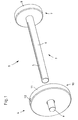
- Loading device 1 shown for loading a stent applicator 2 consists essentially of a cylinder 3 and a piston 4 comprehensive cylinder-piston assembly.
- the cylinder 3 is formed as at least partially provided with a longitudinal slot 5 tube 6, wherein the longitudinal slot 5 extends to the distal end of the cylinder tube 6.
- a handle 7 is arranged, which is formed in the illustrated embodiment as a patch on the proximal end of the cylinder tube 6 disc 8.
- the piston 4 is designed as a rod-shaped punch 9, which in the assembled state of the loading device 1 substantially in a form-fitting manner and in the longitudinal direction the cylinder tube 6 is displaceably mounted in the cylinder tube 6.
- a handle 10 is arranged, which is formed in the illustrated embodiment as attached to the cylinder tube 6 disc 11, which is connected in the region of the cylinder tube 6 formed in the slot 5 via a web 12 with the punch 9. How out Fig. 2 can be seen, the web 12 serves as a non-rotatable guide when moving the punch 9 along the slot 5 of the cylinder tube. 6
- the cylinder-piston assembly is first completed by inserting the punch 9 of the piston 4 in the cylinder tube 6.
- the web 9 connecting the punch 9 with the handle 10 facilitates thereby the tilt-free insertion of the punch 9 into the cylinder tube 6.
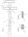
- Fig. 2 shows in top view the loading device 1 with a stent 13 arranged in the cylinder tube 6.
- the exertion of the lateral compressive force D on the stent 13 is usually done manually, but it is also possible to use for exerting the lateral compressive force D on the stent 13, a pressing device, for example in the form of a pair of pliers or a belt.
- a pressing device for example in the form of a pair of pliers or a belt.
- Such a belt which can be used as a pressing device may, for example, be commercially available cable ties.
- the cylinder tube 6 of the loading device 1 is inserted with the distal end first into the stent applicator 2 until the stent 13 is fully received in the stent applicator 2.
- the piston 4 is now displaced so far toward the stent applicator 2 until the distal end of the stamper 8 bears against the proximal end of the stent 13 still located in the cylinder tube 6.
- the actual emptying of the loading device 1 or loading of the stent applicator 2 takes place in the last method step.
- the piston 4 is fixed via the handle 10 in its position to the stent applicator 2 and the cylinder 3 via the handle 7 from the stent applicator 2 continues to be pulled out of the stent applicator 2.
- This relative movement between the piston 3 and the cylinder 4 causes the stent 13 is held by the plunger 9 of the piston 4 in retracting the cylinder 3 in its position in the stent applicator 2 and after complete withdrawal of the cylinder 3 completely and ready for subsequent surgical Placement is placed in the stent applicator 2.
- the stent 13 arranged in the cylinder tube 6 can be actively pushed out of the cylinder tube 6 via the plunger 9 of the piston 4.
- the cylinder tube 6 is inserted only a short distance into the stent applicator 2 and then displaced by fixing the cylinder 3 in this position in the stent applicator 2 of the piston 4 forward to the stent applicator 2 until the punch 9 the stent 13 completely out of the cylinder tube 6 and has pressed into the stent applicator 2 inside.
- the loading device 1 described above is particularly advantageous for loading a stent applicator 2 with wire mesh stents 13, since the actual insertion of the stent 13 into the stent applicator 2 takes place without manual intervention, whereby a risk of injury to the user of the loading device 1 by the sharp and pointed ends of Drahtgeflechtstents 13 can be excluded.
Landscapes
- Health & Medical Sciences (AREA)
- Engineering & Computer Science (AREA)
- Biomedical Technology (AREA)
- Cardiology (AREA)
- Oral & Maxillofacial Surgery (AREA)
- Transplantation (AREA)
- Heart & Thoracic Surgery (AREA)
- Vascular Medicine (AREA)
- Life Sciences & Earth Sciences (AREA)
- Animal Behavior & Ethology (AREA)
- General Health & Medical Sciences (AREA)
- Public Health (AREA)
- Veterinary Medicine (AREA)
- Media Introduction/Drainage Providing Device (AREA)
Applications Claiming Priority (1)
| Application Number | Priority Date | Filing Date | Title |
|---|---|---|---|
| DE102008036205A DE102008036205A1 (de) | 2008-08-02 | 2008-08-02 | Verfahren und Vorrichtung zum Beladen eines Stentapplikators |
Publications (2)
| Publication Number | Publication Date |
|---|---|
| EP2149356A2 true EP2149356A2 (fr) | 2010-02-03 |
| EP2149356A3 EP2149356A3 (fr) | 2010-04-28 |
Family
ID=41259390
Family Applications (1)
| Application Number | Title | Priority Date | Filing Date |
|---|---|---|---|
| EP09009963A Withdrawn EP2149356A3 (fr) | 2008-08-02 | 2009-08-01 | Procédé et dispositif destinés au chargement d'un applicateur de stent |
Country Status (3)
| Country | Link |
|---|---|
| US (1) | US20100057182A1 (fr) |
| EP (1) | EP2149356A3 (fr) |
| DE (1) | DE102008036205A1 (fr) |
Families Citing this family (2)
| Publication number | Priority date | Publication date | Assignee | Title |
|---|---|---|---|---|
| US10159586B2 (en) * | 2015-06-29 | 2018-12-25 | 480 Biomedical Inc. | Scaffold loading and delivery systems |
| ES1226710Y (es) * | 2018-10-30 | 2019-06-10 | Tractivus Sl | Sistema introductor de stent traqueal |
Citations (1)
| Publication number | Priority date | Publication date | Assignee | Title |
|---|---|---|---|---|
| DE10249927B3 (de) | 2002-10-26 | 2004-03-04 | Karl Storz Gmbh & Co. Kg | Vorrichtung zum Komprimieren rohrförmiger Endoprothesen sowie zum Einführen einer komprimierten Endoprothese in ein Applikationsrohr |
Family Cites Families (20)
| Publication number | Priority date | Publication date | Assignee | Title |
|---|---|---|---|---|
| WO1996037167A1 (fr) * | 1995-05-25 | 1996-11-28 | Raychem Corporation | Ensemble prothese endovasculaire |
| US5810869A (en) * | 1996-11-18 | 1998-09-22 | Localmed, Inc. | Methods for loading coaxial catheters |
| IT1286780B1 (it) * | 1996-11-20 | 1998-07-17 | Bard Galway Ltd | Dispositivo per montare una endoprotesi tubolare per impianto vascolare su un catetere di trasporto ed espansione |
| US5928258A (en) * | 1997-09-26 | 1999-07-27 | Corvita Corporation | Method and apparatus for loading a stent or stent-graft into a delivery sheath |
| US6024737A (en) * | 1998-02-25 | 2000-02-15 | Advanced Cardiovascular Systems, Inc. | Stent crimping device |
| US6202272B1 (en) * | 1998-02-26 | 2001-03-20 | Advanced Cardiovascular Systems, Inc. | Hand-held stent crimping device |
| EP0941713B1 (fr) * | 1998-03-04 | 2004-11-03 | Schneider (Europe) GmbH | Dispositif pour introduire une endoprothèse dans le tube d' un cathéter |
| US6051002A (en) * | 1998-10-09 | 2000-04-18 | Advanced Cardiovascular Systems, Inc. | Stent crimping device and method of use |
| DE19851846A1 (de) * | 1998-11-10 | 2000-05-18 | Jomed Implantate Gmbh | Crimp-Vorrichtung |
| DE19906957B4 (de) * | 1999-02-19 | 2007-07-12 | Qualimed Innovative Medizin-Produkte Gmbh | Inlett zur Verwendung beim Krimpen eines Stents und Krimpwerkzeug |
| US6090035A (en) * | 1999-03-19 | 2000-07-18 | Isostent, Inc. | Stent loading assembly for a self-expanding stent |
| US6387117B1 (en) * | 1999-09-22 | 2002-05-14 | Scimed Life Systems, Inc. | Stent crimping system |
| US6309383B1 (en) * | 2000-01-20 | 2001-10-30 | Isostent, Inc. | Stent crimper apparatus with radiation shied |
| US6859986B2 (en) * | 2003-02-20 | 2005-03-01 | Cordis Corporation | Method system for loading a self-expanding stent |
| US7316147B2 (en) * | 2004-01-29 | 2008-01-08 | Boston Scientific Scimed, Inc. | Apparatuses for crimping and loading of intraluminal medical devices |
| ATE458458T1 (de) * | 2006-03-24 | 2010-03-15 | Cordis Corp | Splitschleusenfreisetzungssystem für selbstexpandierende stents |
| FR2902641B1 (fr) * | 2006-06-22 | 2008-09-26 | Tokendo Soc Par Actions Simpli | Dispositif de chargement de protheses |
| US7815670B2 (en) * | 2006-07-11 | 2010-10-19 | Boston Scientific Scimed, Inc. | Method of loading a medical endoprosthesis through the side wall of an elongate member |
| WO2009111241A2 (fr) * | 2008-02-29 | 2009-09-11 | The Florida International University Board Of Trustees | Prothèse de valvule cardiaque artificielle à plusieurs feuillets destinée à être mise en place par un cathéter, et système de mise en place intravasculaire pour une prothèse de valvule cardiaque destinée à être mise en place par un cathéter |
| ATE556679T1 (de) * | 2008-04-09 | 2012-05-15 | Cook Medical Technologies Llc | Ladegerät und verfahren für expandierbare intraluminale medizinische vorrichtungen |
-
2008
- 2008-08-02 DE DE102008036205A patent/DE102008036205A1/de not_active Withdrawn
-
2009
- 2009-08-01 EP EP09009963A patent/EP2149356A3/fr not_active Withdrawn
- 2009-08-03 US US12/534,218 patent/US20100057182A1/en not_active Abandoned
Patent Citations (1)
| Publication number | Priority date | Publication date | Assignee | Title |
|---|---|---|---|---|
| DE10249927B3 (de) | 2002-10-26 | 2004-03-04 | Karl Storz Gmbh & Co. Kg | Vorrichtung zum Komprimieren rohrförmiger Endoprothesen sowie zum Einführen einer komprimierten Endoprothese in ein Applikationsrohr |
Also Published As
| Publication number | Publication date |
|---|---|
| EP2149356A3 (fr) | 2010-04-28 |
| US20100057182A1 (en) | 2010-03-04 |
| DE102008036205A1 (de) | 2010-02-04 |
Similar Documents
| Publication | Publication Date | Title |
|---|---|---|
| EP1156746B1 (fr) | Instrument pour couper des tissus biologiques et notamment des tissus humains | |
| EP2931187B1 (fr) | Applicateur de stent | |
| EP1648313B1 (fr) | Dispositif de mise en place endoscopique de clips medicaux se refermant automatiquement | |
| DE102004013406B4 (de) | Steuergriff für intraluminale Vorrichtungen | |
| DE102007010305A1 (de) | Vorrichtung zum Freisetzen eines selbstexpandierenden Stents in ein Körpergefäß | |
| DE112009001442T5 (de) | Medizinisches Behandlungsinstrument für ein rohrförmiges Organ | |
| DE102006004123A1 (de) | Einführsystem für Stents mit Zug-Druck-Kinematik | |
| DE102008053809A1 (de) | Chirurgisches Fadenpositioniersystem zum Verschließen einer Öffnung innerhalb einer Gewebewand | |
| WO2008068564A2 (fr) | Instrument chirurgical pour implanter un fil métallique, de préférence dans un os | |
| DE102010038975A1 (de) | Zylinder für eine Penisprothese mit entfernbarem Führungsmittel | |
| EP1865885A1 (fr) | Outil d'implantation de lentilles intra-oculaires | |
| EP0637432B1 (fr) | Instrument pour contourner | |
| DE10249927B3 (de) | Vorrichtung zum Komprimieren rohrförmiger Endoprothesen sowie zum Einführen einer komprimierten Endoprothese in ein Applikationsrohr | |
| CH714669A2 (de) | Vorrichtung und Verfahren zum Reinigen des äusseren Gehörgangs. | |
| EP0510624B1 (fr) | Cathéter à guidage avec région terminale précourbée | |
| EP2149356A2 (fr) | Procédé et dispositif destinés au chargement d'un applicateur de stent | |
| WO2011076390A1 (fr) | Dispositif pour placer un implant médical et agencement comprenant un tel dispositif | |
| WO2009071581A1 (fr) | Dispositif rapporté pour dispositif chirurgical et dispositif chirurgical correspondant pour percer un os | |
| DE102016118304A1 (de) | Komponente für ein medizinisches Instrument und medizinisches Instrument | |
| DE102013104565B3 (de) | Pusher-Baugruppe für ein Einführsystem für ein selbstexpandierendes Gefäßimplantat sowie ein entsprechendes Einführsystem | |
| EP2364610A1 (fr) | Pince à pincement | |
| DE102007032482A1 (de) | Vorrichtung zur intrakorporalen Applikation medizinischer Hilfsmittel | |
| DE102013217614B3 (de) | Stent-Falt- und Ladevorrichtung sowie Bronchoskopsystem | |
| DE102016111184B3 (de) | Hilfsmittel zum Verknoten von Luftballons | |
| EP2921143B1 (fr) | Instrument de tampon et système comprenant celui-ci destiné à traiter une structure osseuse ou de cartilage |
Legal Events
| Date | Code | Title | Description |
|---|---|---|---|
| PUAI | Public reference made under article 153(3) epc to a published international application that has entered the european phase |
Free format text: ORIGINAL CODE: 0009012 |
|
| AK | Designated contracting states |
Kind code of ref document: A2 Designated state(s): AT BE BG CH CY CZ DE DK EE ES FI FR GB GR HR HU IE IS IT LI LT LU LV MC MK MT NL NO PL PT RO SE SI SK SM TR |
|
| AX | Request for extension of the european patent |
Extension state: AL BA RS |
|
| PUAL | Search report despatched |
Free format text: ORIGINAL CODE: 0009013 |
|
| AK | Designated contracting states |
Kind code of ref document: A3 Designated state(s): AT BE BG CH CY CZ DE DK EE ES FI FR GB GR HR HU IE IS IT LI LT LU LV MC MK MT NL NO PL PT RO SE SI SK SM TR |
|
| AX | Request for extension of the european patent |
Extension state: AL BA RS |
|
| STAA | Information on the status of an ep patent application or granted ep patent |
Free format text: STATUS: THE APPLICATION IS DEEMED TO BE WITHDRAWN |
|
| 18D | Application deemed to be withdrawn |
Effective date: 20101029 |