EP2149385A1 - Ballonkatheter und Hüllenherstellungsverfahren - Google Patents
Ballonkatheter und Hüllenherstellungsverfahren Download PDFInfo
- Publication number
- EP2149385A1 EP2149385A1 EP09009798A EP09009798A EP2149385A1 EP 2149385 A1 EP2149385 A1 EP 2149385A1 EP 09009798 A EP09009798 A EP 09009798A EP 09009798 A EP09009798 A EP 09009798A EP 2149385 A1 EP2149385 A1 EP 2149385A1
- Authority
- EP
- European Patent Office
- Prior art keywords
- sheath
- diameter portion
- balloon
- outer diameter
- balloon catheter
- Prior art date
- Legal status (The legal status is an assumption and is not a legal conclusion. Google has not performed a legal analysis and makes no representation as to the accuracy of the status listed.)
- Granted
Links
Images





Classifications
-
- A—HUMAN NECESSITIES
- A61—MEDICAL OR VETERINARY SCIENCE; HYGIENE
- A61M—DEVICES FOR INTRODUCING MEDIA INTO, OR ONTO, THE BODY; DEVICES FOR TRANSDUCING BODY MEDIA OR FOR TAKING MEDIA FROM THE BODY; DEVICES FOR PRODUCING OR ENDING SLEEP OR STUPOR
- A61M25/00—Catheters; Hollow probes
- A61M25/10—Balloon catheters
- A61M25/1027—Making of balloon catheters
- A61M25/1036—Making parts for balloon catheter systems, e.g. shafts or distal ends
-
- B—PERFORMING OPERATIONS; TRANSPORTING
- B29—WORKING OF PLASTICS; WORKING OF SUBSTANCES IN A PLASTIC STATE IN GENERAL
- B29C—SHAPING OR JOINING OF PLASTICS; SHAPING OF MATERIAL IN A PLASTIC STATE, NOT OTHERWISE PROVIDED FOR; AFTER-TREATMENT OF THE SHAPED PRODUCTS, e.g. REPAIRING
- B29C61/00—Shaping by liberation of internal stresses; Making preforms having internal stresses; Apparatus therefor
-
- A—HUMAN NECESSITIES
- A61—MEDICAL OR VETERINARY SCIENCE; HYGIENE
- A61M—DEVICES FOR INTRODUCING MEDIA INTO, OR ONTO, THE BODY; DEVICES FOR TRANSDUCING BODY MEDIA OR FOR TAKING MEDIA FROM THE BODY; DEVICES FOR PRODUCING OR ENDING SLEEP OR STUPOR
- A61M25/00—Catheters; Hollow probes
- A61M25/0021—Catheters; Hollow probes characterised by the form of the tubing
- A61M25/0023—Catheters; Hollow probes characterised by the form of the tubing by the form of the lumen, e.g. cross-section, variable diameter
-
- A—HUMAN NECESSITIES
- A61—MEDICAL OR VETERINARY SCIENCE; HYGIENE
- A61M—DEVICES FOR INTRODUCING MEDIA INTO, OR ONTO, THE BODY; DEVICES FOR TRANSDUCING BODY MEDIA OR FOR TAKING MEDIA FROM THE BODY; DEVICES FOR PRODUCING OR ENDING SLEEP OR STUPOR
- A61M25/00—Catheters; Hollow probes
- A61M25/10—Balloon catheters
-
- B—PERFORMING OPERATIONS; TRANSPORTING
- B29—WORKING OF PLASTICS; WORKING OF SUBSTANCES IN A PLASTIC STATE IN GENERAL
- B29C—SHAPING OR JOINING OF PLASTICS; SHAPING OF MATERIAL IN A PLASTIC STATE, NOT OTHERWISE PROVIDED FOR; AFTER-TREATMENT OF THE SHAPED PRODUCTS, e.g. REPAIRING
- B29C55/00—Shaping by stretching, e.g. drawing through a die; Apparatus therefor
- B29C55/22—Shaping by stretching, e.g. drawing through a die; Apparatus therefor of tubes
-
- B—PERFORMING OPERATIONS; TRANSPORTING
- B29—WORKING OF PLASTICS; WORKING OF SUBSTANCES IN A PLASTIC STATE IN GENERAL
- B29C—SHAPING OR JOINING OF PLASTICS; SHAPING OF MATERIAL IN A PLASTIC STATE, NOT OTHERWISE PROVIDED FOR; AFTER-TREATMENT OF THE SHAPED PRODUCTS, e.g. REPAIRING
- B29C61/00—Shaping by liberation of internal stresses; Making preforms having internal stresses; Apparatus therefor
- B29C61/06—Making preforms having internal stresses, e.g. plastic memory
- B29C61/08—Making preforms having internal stresses, e.g. plastic memory by stretching tubes
-
- B—PERFORMING OPERATIONS; TRANSPORTING
- B29—WORKING OF PLASTICS; WORKING OF SUBSTANCES IN A PLASTIC STATE IN GENERAL
- B29L—INDEXING SCHEME ASSOCIATED WITH SUBCLASS B29C, RELATING TO PARTICULAR ARTICLES
- B29L2031/00—Other particular articles
- B29L2031/753—Medical equipment; Accessories therefor
- B29L2031/7542—Catheters
Definitions
- the present invention relates to a balloon catheter for use in combination with a side view endoscope in medical treatment and the like, and a method for fabricating a sheath for use in the balloon catheter.
- Priority is claimed on United States Patent Application No. 12/181,385, filed July 29, 2008 . The contents of which are incorporated herein by reference.
- a balloon catheter with a balloon attached at the distal end has been used as medical equipment for removing gallstones and the like.
- cannulation is performed from the duodenal papilla into the bile duct, and in the bile duct, the balloon is inflated to about a size which allows the balloon to be contacted with the bile duct wall. Then, the inflated balloon is used to rake gallstones out of the bile duct.
- the abovementioned balloon catheter is required to have properties such as a high cannulation capability (insertability) into the bile duct, and a capability of inflating the balloon to a size which allows close contact with the inner wall of the bile duct.
- the maximum inflation diameter of the balloon is mostly determined by the material of the balloon, the dimension of the inner diameter of the balloon when deflated, and the like. Accordingly, to achieve a greater maximum inflation diameter, it is necessary to increase the dimension of the deflated balloon to greater than that of a conventional balloon catheter, if the same material is used for these balloons.
- a balloon catheter comprising a so-called barrel-shaped or lantern-shaped balloon in which only the central portion is formed thick and the axial ends to be fixed to the catheter are formed thin, so as to increase the maximum inflation diameter of the balloon while retaining thinness of the outer diameter of the catheter's distal end (for example, refer to Japanese Unexamined Patent Application, First Publication No. 2001-46378 ).
- a first aspect of the present invention is a balloon catheter comprising: a flexible sheath which has at least one lumen; and a cylindrical balloon which is fixed to the outer peripheral surface of the sheath and can be inflated with a fluid supplied from the lumen; wherein the sheath has a large diameter portion whose outer diameter is greater than a basic outer diameter thereof, and the balloon is set to have a maximum inner diameter greater than the basic outer diameter when deflated, and is attached to the outer peripheral surface of the large diameter portion.
- basic outer diameter refers to the outer diameter dimension in a region of the sheath where the large diameter portion is formed.
- a second aspect of the present invention is a balloon catheter comprising: a flexible sheath which has at least one lumen; and a cylindrical balloon which is fixed to the outer peripheral surface of the sheath and can be inflated with a fluid supplied from the lumen; wherein the sheath has a small diameter portion on a distal side, and a large diameter portion which is formed to have an outer diameter greater than that of the small diameter portion at equal diameter all over the full length, on a proximal side from the small diameter portion, and the balloon is set to have a maximum inner diameter equal to the large diameter portion when deflated.
- a third aspect of the present invention is a method of fabricating a sheath for use in a balloon catheter, comprising: a first step of forming a basic outer diameter portion by softening the distal end of the sheath having an initial outer diameter by heating to a predetermined temperature, and pulling the distal end in the axial direction to make the outer diameter of the distal end smaller than the initial outer diameter; and after the first step, a second step of forming a large diameter portion by reheating a partial region of the basic outer diameter portion excluding the distal end thereof, and making the outer diameter of the partial region greater than the basic outer diameter with aid of residual strain occurring in the basic outer diameter portion.
- a balloon catheter 1 of the present embodiment comprises; a long and flexible sheath 2, a balloon 3 attached to an outer peripheral surface of the sheath 2, and a controller 4 attached to a proximal end of the sheath 2.
- the sheath 2 comprises a first sheath 5 on the distal side, and a second sheath 6 connected to the proximal end of the first sheath 5.
- various types of resins may be suitably employed such as fluorine-based resins including polytetrafluoroethylene (PTFE), polyolefin-based resins, polyurethane, polyamide, and polyamide elastomers.
- the first sheath 5 to be inserted into the body cavity is formed of a fluorine-based resin in consideration of biocompatibility, insertability into the bile duct (such as firmness, slidability, and flexibility), the slidability with respect to a guide wire, and the like, while the second sheath 6 mostly located in the channel of the endoscope is formed of a rigid and inexpensive resin such as polyamide in consideration of transferability of a pushing force (pushability), tensile strength, production cost, and the like.
- the basic outer diameter of the sheath 2 is defined as the outer diameter D1 (refer to FIG 2 ) of a region in the sheath 2 where a large diameter portion that will be described later is formed. Its value is set at 1.8 mm, for example.
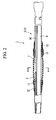
- FIG 2 is an enlarged cross-sectional view of a distal side of the first sheath 5
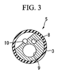
- FIG. 3 is a cross-sectional view taken along the line A-A of FIG 2 .
- a large diameter portion 7 having an outer diameter greater than the basic outer diameter D1.
- Axially opposite ends of the large diameter portion are respectively formed in a tapered shape of gradually decreasing diameter.
- An intermediate portion excluding the opposite ends thereof is set to have a constant diameter at a value greater than the basic outer diameter D1, for example, about 2.4 mm.
- the first sheath 5 is provided with three lumens: a first lumen 8 for supplying a liquid such as a contrast medium from the distal end; a second lumen 9 for insertion of a guide wire that will be described later; and a third lumen 10 for supplying a fluid into the balloon 3 to effect inflation.
- a first lumen 8 for supplying a liquid such as a contrast medium from the distal end
- a second lumen 9 for insertion of a guide wire that will be described later
- a third lumen 10 for supplying a fluid into the balloon 3 to effect inflation.
- the first lumen 8 communicates from a vicinity of the distal end of the first sheath 5 to the proximal end of the second sheath 6.
- the second lumen 9 communicates from the distal end of the first sheath 5 which is on the distal side from the large diameter portion 7, to the proximal end of the first sheath 5.
- the third lumen 10 is open to the outer peripheral surface of the large diameter portion 7, and communicates to the proximal end of the second sheath.
- the first sheath 5 takes such a triple lumen structure provided with the respective lumens 8, 9, and 10, while the second sheath 6 takes a double lumen structure provided with the first lumen 8 and the third lumen 10 only.
- a detailed configuration of a connection between the first sheath 5 and the second sheath 6 will be described later.
- the balloon 3 is an approximately cylindrical member formed of an elastic member such as latex rubber, into which the sheath 2 is inserted so as to cover the outer peripheral surface of the large diameter portion 7, and the axially opposite ends of which are fixed to the sheath 2 in an airtight manner.
- an elastic member such as latex rubber
- the axially opposite ends of the balloon 3 are fixed to portions which respectively have an outer diameter approximately the same as the basic outer diameter D1, and which are adjacent to the large diameter portion 7, with a thread 11 and an adhesive 12.
- a fixing method using wound thread and an adhesive other methods such as thermal welding and laser welding may also be appropriately used.
- the axially opposite ends of the balloon 3 are fixed to the sheath 2 in an airtight manner, which thereby enables inflation and deflation of the balloon 3 by supplying and recovering a fluid through the third lumen 10.
- the inner diameter of the balloon 3 when deflated is set at about 2.4 mm, which is approximately equal to the outer diameter of the large diameter portion 7. For this reason, in a state where the balloon 3 is attached to the large diameter portion 7, the balloon 3 is closely contacted with the outer peripheral surface of the large diameter portion 7 without the occurrence of sagging.
- the balloon 3 may also be attached to the large diameter portion 7 in an axially-extended state.
- the inner diameter of the balloon 3 when deflated can be set at about 2.6 mm before attachment of the balloon, which enables a greater inflation diameter.
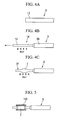
- FIG. 4A to FIG. 5 show an example of the fabrication method for forming the large diameter portion 7 on the first sheath 5.
- the user heats the distal end 13 of the first sheath 5 having an initial outer diameter, until it becomes a softened state.
- the glass transition point of the material of the first sheath 5 may be used as a guide, however the heating temperature may be appropriately adjusted according to various conditions.
- the distal end 13 is sufficiently softened, as shown in FIG 4B the distal end 13 is pulled in the axial direction to effect elongation, so as to form a basic outer diameter portion 14 having a diameter smaller than the initial outer diameter on the distal side of the first sheath 5 (first step).
- first step the first sheath 5 is formed with the basic outer diameter portion 14 on the distal side and the initial outer diameter portion 5A on the proximal side.
- residual strain occurs due to the elongation.
- the user reheats a partial region of the basic outer diameter portion 14 excluding the distal end to about the same degree as that of the first step, so as to soften the region. Then, as shown in FIG. 4C , the softened part of the basic outer diameter portion 14 recedes back in the axial direction due to the residual strain that has occurred in the first step. Accordingly, the outer diameter of the heated part is increased to a value greater than the basic outer diameter (second step).
- the large diameter portion 7 is formed in this manner.
- the formation of the large diameter portion 7 in this manner is easier than a normal shaping method with regard to the formation of the large diameter portion.
- the large diameter portion can be suitably formed by the above fabrication method.
- the initial outer diameter portion 5A which is greater than the basic outer diameter portion 14 remains on the proximal side, the pushability is retained and the operation for pushing the sheath by the user is satisfactorily transferred to the distal end.
- the large diameter portion 7 of this embodiment is formed so as to have an approximately constant diameter along the axial direction by performing the abovementioned second step in a state where, as shown in FIG 5 , the sheath 2 is inserted into an approximately cylindrical jig 100.
- FIG 6 is an enlarged cross-sectional view of the joint between the first sheath 5 and the second sheath 6.
- the second lumen 9 is open in the vicinity of the proximal end of the first sheath 5. That is, the balloon catheter 1 is constituted as a so-called monorail type in which the guide wire is inserted into the first sheath 5 only.
- the first sheath 5 and the second sheath 6 are integrally connected with use of a thread 17 and an adhesive 18 in a state where the first lumens 8 of the respective sheaths are connected with each other by using an auxiliary pipe 15 and the third lumens 10 of the respective sheaths are connected with each other by using an auxiliary pipe 16.
- the sheath 2 comprising the first sheath 5 and the second sheath 6 is formed in this manner.
- the approximately cylindrical second sheath 6 takes the double lumen structure comprising the first lumen 8 and the third lumen 10 as mentioned above, there is no need for providing the second lumen 9, and thus for that amount the inner diameters of the first lumen 8 and the third lumen 10 can be set greater. Accordingly, the fluid supplying and recovering efficiency for sending or sucking a gas/liquid etc. through these lumens 8 and 10 can be improved to enable constitution of a balloon catheter which can provide better manipulation performance.
- the outer diameter of the second sheath 6 is set at, for example, 2.0 mm so that a general-purpose guide wire having an outer diameter of 0.035 inches (0.089 mm) and an endoscope having a channel's inner diameter of 3.2 mm can be combined therewith for use in a monorail manner.
- the controller 4 attached to the proximal end of the second sheath 6 comprises; a main body 19, a fixation section 20 attached to the main body 19, a first port 21 communicating with the first lumen 8, and a second port 22 communicating with the third lumen 10.
- the fixation section 20 is a commonly known type formed in an approximate C-shape, which is capable of fixing the balloon catheter 1 to an endoscope or the like by engaging with the handle or the like of the endoscope as required.
- a syringe (not shown) or the like may be connected to the first port 21 so that a contrast medium or the like can be supplied into the first lumen 8.
- a syringe (not shown) or the like may be connected to the second port 22, too, so that a fluid such as air or a physiological salt solution for inflating the balloon 3 can be supplied into the third lumen 10.
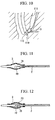
- the user inserts a side view endoscope from a natural opening such as the mouth into the body cavity of the patient, and moves the distal end of the endoscope 101 forward to a vicinity of the duodenal papilla 110 as shown in FIG. 8 .
- the user inserts the guide wire 102 from the forceps port (not shown) of the endoscope 101 and makes the distal end of the guide wire 102 protrude toward the duodenal papilla 110 while appropriately operating a raising base (not shown). Then, the distal end of the guide wire 102 is inserted from the duodenal papilla 110 into the bile duct 111.
- the user inserts the proximal end of the guide wire 102 into the distal opening of the second lumen 9 of the balloon catheter 1 and makes it protrude from the proximal opening, to thereby insert the guide wire 102 into the second lumen 9.
- the balloon catheter 1 is inserted from the forceps port into the channel of the endoscope 101, and is moved along the guide wire 102 into the bile duct 111.
- the deflated balloon 3 is closely contacted with the large diameter portion 7 without sagging, and thus will not be torn by being caught on the raising base or the like.
- the user After the balloon catheter 1 has been inserted into the bile duct 111, the user operates a syringe (not shown) connected to the first port 21 to eject a contrast medium from the distal end of the first lumen 8, and confirms the location of the gallstones 112 under radioscopy. Then, the balloon catheter is moved forward deeply into the bile duct 111 until the large diameter portion 7 is located at the rear of the gallstones 112.
- the large diameter portion 7 is made radiopaque by mixing a radiopaque material in the material for forming the sheath 2, in particular the large diameter portion 7, then the positional relation between the gallstones 112 and the large diameter portion 7 can be readily and accurately comprehended by the user.
- the user When the large diameter portion 7 has been moved forward to reach the rear of the gallstones 112, the user operates a syringe (not shown) connected to the second port 22 to supply air or a fluid such as a physiological salt solution into the third lumen 10.
- the supplied fluid is then injected into the cavity of the balloon 3 from the opening of the third lumen 10 provided on the outer peripheral surface of the large diameter portion 7, and as a result the balloon 3 is inflated as shown in FIG 9 .
- the maximum inner diameter of the balloon 3 when deflated is set at about 2.4 mm, which is greater than that of a general balloon for use in stone removal. Accordingly, even if the inner diameter of the bile duct 111 is expanded up to about, for example, 20 mm due to bile stasis or the like because of the gallstones 112, the balloon 3 can be inflated to have a diameter approximately the same as that of the bile duct 112 to effect close contact with the inner wall of the bile duct 111.
- the sheath 2 is provided with the large diameter portion 7 having an outer diameter greater than the basic outer diameter D1 and the balloon 3 is attached to the outer peripheral surface of the large diameter portion 7, then even a balloon whose diameter when deflated is set large so as to obtain a greater inflation diameter can be attached to the sheath without the occurrence of sagging.
- the balloon catheter when the balloon catheter is inserted into the forceps port of the endoscope, protruded from the distal end of the channel disposed with the raising base, or withdrawn into the channel, the balloon can be suitably prevented from being caught thereon and torn.
- the insertability of the sheath can be satisfactorily configured even with the large diameter portion 7.
- the axially opposite ends of the balloon 3 are fixed to portions of the outer surface of the sheath which respectively have an outer diameter smaller than that of the large diameter portion 7, and which are adjacent to the large diameter portion 7. Accordingly, since the step made by the large diameter portion 7 functions as a stopper against the fixation section, it is possible to suitably prevent the axial displacement of the balloon 3 occurring when the balloon catheter 1 is being inserted or when the gallstones are being raked by the balloon.
- a large diameter portion 7A may also be formed in an approximately spindle shape which has the greatest outer diameter in the axial center. In this case, since the surface of the sheath 2 can be smoothly formed as a whole, the insertability of the balloon catheter 1 and the withdrawal property at the time of stone removal can be further improved.
- Such a large diameter portion 7A can be readily formed by not using the cylindrical jig 100 in the abovementioned second step.
- the large diameter portion is to be formed in such a shape, it is preferable to form the balloon in a so-called barrel-shape or lantern-shape fitting the large diameter portion because the occurrence of sagging is more suitably prevented.
- a large diameter portion 7B may also be formed by attaching a spacer 23, which is formed in a desired shape, to the outer peripheral surface of the approximately cylindrical sheath 2.
- a desired shape of the large diameter portion can be readily provided on the sheath by using an easy-to-shape material.
- the first sheath may also be formed by joining the basic outer diameter portion and the initial outer diameter portion which have been separately formed.
- the spacer 23 is formed of a soft material, damage of the balloon when touching the projection of the raising base can be reduced.
- the sheath 2 can readily follow the passage of the curved bile duct and the like, which provides a high insertability into the bile duct and the like.
- first sheath 5 and the second sheath 6 are formed of different materials. However they may also be formed of the same material.
- FIG. 13 is a cross-sectional view showing a distal end of a balloon catheter 31 of the present embodiment. Similar to the first embodiment, the sheath 2 is provided with three lumens. However, for the sake of easy understanding of the structure, only the third lumen 10 is shown herein.
- the shape of the large diameter portion 7 is approximately the same as that of the first embodiment, and is formed to have an approximately constant outer diameter along the axial direction.
- the balloon 32 is formed in an approximately cylindrical shape to have an outer diameter, when deflated, approximately the same as the large diameter portion 7 along the axial direction.
- the axially opposite ends 32A of the balloon 32 are fixed to the sheath 2 in an airtight manner, by attaching them to the outer peripheral surface of the large diameter portion 7 with use of a thread, an adhesive, and the like.
- the balloon catheter 31 of this embodiment is also able to provide the same effect to that of the balloon catheter 1 of the first embodiment.
- the axially opposite ends 32A of the balloon 32 are fixed to the outer peripheral surface of the large diameter portion 7 whose outer diameter is approximately constant along the axial direction, then wrinkles, sagging, and the like hardly occur in the fixed ends 32A even if the cylindrical balloon 32 were used. Accordingly, there is no need of modification to reduce the inner diameter of the axial ends of the balloon so as to eliminate sagging and the like in the fixed part. Therefore, the balloon modification can be omitted so that the balloon catheter can achieve better production efficiency.
- the large diameter portion 7 may also be formed with use of a spacer 23.
- the outer diameter of the large diameter portion is approximately constant along the axial direction, there is no need of shaping the spacer 23 in a special manner except for providing a hole that communicates with the third lumen 10, and it is possible to improve the production efficiency as compared with the modified example of FIG. 12 where the spacer 23 is used in a similar way.
- FIG. 15 shows a distal end of a balloon catheter 41 of this embodiment. Regarding the lumen, FIG 15 shows only the third lumen 10 similar to FIG 13 .
- the sheath 42 of the balloon catheter 41 comprises only a small diameter portion 43 on the distal side and a large diameter portion 44 on the proximal side from the small diameter portion 43.
- the large diameter portion 44 is continuous at an approximately constant diameter up to the proximal end of the sheath 42.
- the outer diameter of the large diameter portion 44 is set at about 2.4 mm, which is approximately the same as that of the large diameter portion of the other embodiments.
- the distal end of the balloon 45 is fixed to a part of the small diameter portion 43 which is adjacent to the large diameter portion 44.
- the proximal end thereof is fixed to the outer peripheral surface of the large diameter portion 44.
- the balloon catheter 31 of this embodiment similar to the balloon catheter 1 of the first embodiment, the balloon can be prevented from being torn due to catching on the raising base or the like of the endoscope.
- the large diameter portion 44 is continuous at an approximately constant diameter up to the proximal end of the sheath 42, the structure is simplified. As a result, there is no need of a step such as the abovementioned second step in the production, so that the production cost can be reduced.
- the description was made with reference to an example where the balloon catheter is for use in stone removal to extract gallstones or the like.
- the balloon catheter of the present invention is not limited to this, and may also be used, for example, as a balloon catheter for use in expansion of narrowed luminal organs.
- the balloon catheter of the present invention may also be constituted by appropriately omitting these lumens.
- the friction coefficient of the outer peripheral surface of the large diameter portion may be set higher than that of the outer peripheral surface of other parts of the sheath by forming minute corrugations on the outer peripheral surface of the large diameter portion by means of plasma treatment or the like.
Landscapes
- Health & Medical Sciences (AREA)
- Life Sciences & Earth Sciences (AREA)
- Heart & Thoracic Surgery (AREA)
- Engineering & Computer Science (AREA)
- Biophysics (AREA)
- Pulmonology (AREA)
- Child & Adolescent Psychology (AREA)
- Anesthesiology (AREA)
- Biomedical Technology (AREA)
- Hematology (AREA)
- Animal Behavior & Ethology (AREA)
- General Health & Medical Sciences (AREA)
- Public Health (AREA)
- Veterinary Medicine (AREA)
- Media Introduction/Drainage Providing Device (AREA)
Applications Claiming Priority (1)
| Application Number | Priority Date | Filing Date | Title |
|---|---|---|---|
| US12/181,385 US8376992B2 (en) | 2008-07-29 | 2008-07-29 | Balloon catheter and sheath fabrication method |
Publications (2)
| Publication Number | Publication Date |
|---|---|
| EP2149385A1 true EP2149385A1 (de) | 2010-02-03 |
| EP2149385B1 EP2149385B1 (de) | 2016-04-13 |
Family
ID=41328524
Family Applications (1)
| Application Number | Title | Priority Date | Filing Date |
|---|---|---|---|
| EP09009798.1A Not-in-force EP2149385B1 (de) | 2008-07-29 | 2009-07-29 | Ballonkatheter |
Country Status (3)
| Country | Link |
|---|---|
| US (1) | US8376992B2 (de) |
| EP (1) | EP2149385B1 (de) |
| JP (1) | JP5378092B2 (de) |
Families Citing this family (7)
| Publication number | Priority date | Publication date | Assignee | Title |
|---|---|---|---|---|
| US20060079736A1 (en) | 2004-10-13 | 2006-04-13 | Sing-Fatt Chin | Method and device for percutaneous left ventricular reconstruction |
| EP1933756B1 (de) | 2005-08-19 | 2016-07-20 | CHF Technologies Inc. | Lenkbare läsionsausschliessende herzimplantate bei kongestiver herzinsuffizienz |
| AU2012315597B2 (en) | 2011-09-30 | 2016-01-07 | Bioventrix, Inc. | Trans-catheter ventricular reconstruction structures, methods, and systems for treatment of congestive heart failure and other conditions |
| US9653300B2 (en) * | 2013-04-16 | 2017-05-16 | United Microelectronics Corp. | Structure of metal gate structure and manufacturing method of the same |
| WO2015031647A2 (en) * | 2013-08-30 | 2015-03-05 | Bioventrix, Inc. | Cardiac tissue anchoring devices, methods, and systems for treatment of congestive heart failure and other conditions |
| US10490438B2 (en) * | 2014-03-07 | 2019-11-26 | Toshiba Memory Corporation | Non-volatile semiconductor memory device and manufacturing method of p-channel MOS transistor |
| US11478353B2 (en) | 2016-01-29 | 2022-10-25 | Bioventrix, Inc. | Percutaneous arterial access to position trans-myocardial implant devices and methods |
Citations (8)
| Publication number | Priority date | Publication date | Assignee | Title |
|---|---|---|---|---|
| US4188954A (en) | 1976-08-05 | 1980-02-19 | The Kendall Company | Catheter with improved balloon assembly |
| US5121536A (en) * | 1991-01-18 | 1992-06-16 | Applied Vascular Devices, Inc. | Method for making prestressed column |
| JPH0563551B2 (de) | 1984-08-25 | 1993-09-10 | Yasuo Tarui | |
| US5400789A (en) | 1991-10-08 | 1995-03-28 | Griffith; James M. | Sheath for guide wire probe |
| WO2000062852A1 (en) | 1999-04-15 | 2000-10-26 | Intella Interventional Systems | Single lumen balloon catheter |
| JP2001046378A (ja) | 1999-08-06 | 2001-02-20 | Olympus Optical Co Ltd | 超音波プローブ |
| US20020010420A1 (en) * | 1997-03-06 | 2002-01-24 | Celso J Bagaoisan | Balloon catheter and method of manufacture |
| US20070055301A1 (en) | 1995-09-18 | 2007-03-08 | Campbell Carey V | Balloon catheter device |
Family Cites Families (15)
| Publication number | Priority date | Publication date | Assignee | Title |
|---|---|---|---|---|
| US2886853A (en) * | 1954-01-05 | 1959-05-19 | Tno | Process for the production of hollow objects |
| US3634924A (en) * | 1970-04-20 | 1972-01-18 | American Hospital Supply Corp | Method of making multilumen balloon catheter |
| FR2215124A5 (de) * | 1972-12-22 | 1974-08-19 | Pontigny Jacques | |
| US5049132A (en) * | 1990-01-08 | 1991-09-17 | Cordis Corporation | Balloon catheter for delivering therapeutic agents |
| JPH0563551A (ja) | 1991-08-29 | 1993-03-12 | Kawasaki Steel Corp | プログラマブル論理回路装置 |
| JPH05220215A (ja) | 1991-12-20 | 1993-08-31 | Nippon Zeon Co Ltd | カテーテル |
| DE69428721T2 (de) * | 1993-12-10 | 2002-06-20 | Schneider (Usa) Inc., Plymouth | Führungskatheter |
| JPH1033681A (ja) | 1996-07-26 | 1998-02-10 | Aisin Seiki Co Ltd | 大動脈内バルーンカテーテル |
| JPH11244385A (ja) | 1998-03-03 | 1999-09-14 | Kanegafuchi Chem Ind Co Ltd | 医療用バルーンカテーテルシャフト及びその製造方法 |
| US20030163114A1 (en) * | 2002-02-26 | 2003-08-28 | Gershowitz Arthur D. | Retrograde cannula having manually retractable sealing member |
| US20050255317A1 (en) * | 2003-09-22 | 2005-11-17 | Advanced Cardiovascular Systems, Inc. | Polymeric marker with high radiopacity for use in medical devices |
| US7695466B2 (en) * | 2005-07-14 | 2010-04-13 | Beisel Robert F | Stylet free flexible-tip epidural catheter and method of making |
| JP4794258B2 (ja) * | 2005-09-28 | 2011-10-19 | 富士フイルム株式会社 | バルーン装着装置 |
| DE602006017366D1 (de) * | 2006-08-25 | 2010-11-18 | Pulsion Medical Sys Ag | Katheter für die enterale Ernährung und Vorrichtung zur Determinierung des intraabdominalen Druckes |
| EP2114504B1 (de) * | 2007-02-09 | 2013-04-24 | Steven J. Ferry | System zur intraluminalen bewegung in lebenden gefässen |
-
2008
- 2008-07-29 US US12/181,385 patent/US8376992B2/en not_active Expired - Fee Related
-
2009
- 2009-07-24 JP JP2009173537A patent/JP5378092B2/ja not_active Expired - Fee Related
- 2009-07-29 EP EP09009798.1A patent/EP2149385B1/de not_active Not-in-force
Patent Citations (8)
| Publication number | Priority date | Publication date | Assignee | Title |
|---|---|---|---|---|
| US4188954A (en) | 1976-08-05 | 1980-02-19 | The Kendall Company | Catheter with improved balloon assembly |
| JPH0563551B2 (de) | 1984-08-25 | 1993-09-10 | Yasuo Tarui | |
| US5121536A (en) * | 1991-01-18 | 1992-06-16 | Applied Vascular Devices, Inc. | Method for making prestressed column |
| US5400789A (en) | 1991-10-08 | 1995-03-28 | Griffith; James M. | Sheath for guide wire probe |
| US20070055301A1 (en) | 1995-09-18 | 2007-03-08 | Campbell Carey V | Balloon catheter device |
| US20020010420A1 (en) * | 1997-03-06 | 2002-01-24 | Celso J Bagaoisan | Balloon catheter and method of manufacture |
| WO2000062852A1 (en) | 1999-04-15 | 2000-10-26 | Intella Interventional Systems | Single lumen balloon catheter |
| JP2001046378A (ja) | 1999-08-06 | 2001-02-20 | Olympus Optical Co Ltd | 超音波プローブ |
Also Published As
| Publication number | Publication date |
|---|---|
| EP2149385B1 (de) | 2016-04-13 |
| US8376992B2 (en) | 2013-02-19 |
| JP2010029662A (ja) | 2010-02-12 |
| JP5378092B2 (ja) | 2013-12-25 |
| US20100030142A1 (en) | 2010-02-04 |
Similar Documents
| Publication | Publication Date | Title |
|---|---|---|
| JP4986176B2 (ja) | 経皮的気管切開用の挿入補助具 | |
| US20210322035A1 (en) | Increased axial load carrying sheathed irrigating balloon catheter | |
| JP4929351B2 (ja) | 気管瘻に気管カニューレを挿入するための装置 | |
| EP3795199B1 (de) | Ballonkatheter | |
| EP2149385B1 (de) | Ballonkatheter | |
| JP4791654B2 (ja) | 浮動スチフナーを有するバルーンカテーテル及び方法 | |
| US9446218B2 (en) | Microcatheter tip | |
| US9987025B2 (en) | Increased axial load carrying sheathed irrigating balloon catheter | |
| US20080306441A1 (en) | Non-buckling balloon catheter with spring loaded floating flexible tip | |
| US20060052750A1 (en) | Expandable transluminal sheath | |
| US20020055746A1 (en) | Method and apparatus for extracting foreign bodies from nasal passages and the like | |
| US20040236366A1 (en) | Non-buckling balloon catheter | |
| CN103118584A (zh) | 用于治疗鼻窦疾病的设备 | |
| EP2394689B1 (de) | Lagervorrichtung für einen Ballonkatheter | |
| WO2005016437A1 (en) | Catheter with full-length core wire shaft for core wire iinterchangeability | |
| CN105392517A (zh) | 可拆开导管 | |
| US20150297201A1 (en) | Fistula management device and method | |
| JP3958086B2 (ja) | 拡張バルーンカテーテル | |
| US11351346B2 (en) | Balloon sheath and associated methods | |
| JP3843635B2 (ja) | 拡張カテーテル | |
| JP7603471B2 (ja) | カテーテルシステム | |
| JP2007531589A (ja) | 拡大遷移半径を有する医療用バルーン | |
| CN115430015B (zh) | 导尿装置 | |
| CN222238531U (zh) | 一种封堵球囊导管组件 | |
| US12458784B2 (en) | Balloon dilation device |
Legal Events
| Date | Code | Title | Description |
|---|---|---|---|
| PUAI | Public reference made under article 153(3) epc to a published international application that has entered the european phase |
Free format text: ORIGINAL CODE: 0009012 |
|
| AK | Designated contracting states |
Kind code of ref document: A1 Designated state(s): AT BE BG CH CY CZ DE DK EE ES FI FR GB GR HR HU IE IS IT LI LT LU LV MC MK MT NL NO PL PT RO SE SI SK SM TR |
|
| AX | Request for extension of the european patent |
Extension state: AL BA RS |
|
| 17P | Request for examination filed |
Effective date: 20100419 |
|
| 17Q | First examination report despatched |
Effective date: 20100608 |
|
| REG | Reference to a national code |
Ref country code: DE Ref legal event code: R079 Ref document number: 602009037652 Country of ref document: DE Free format text: PREVIOUS MAIN CLASS: A61M0025000000 Ipc: A61M0025100000 |
|
| RIC1 | Information provided on ipc code assigned before grant |
Ipc: A61M 25/00 20060101ALI20150916BHEP Ipc: A61M 25/10 20130101AFI20150916BHEP |
|
| GRAP | Despatch of communication of intention to grant a patent |
Free format text: ORIGINAL CODE: EPIDOSNIGR1 |
|
| RAP1 | Party data changed (applicant data changed or rights of an application transferred) |
Owner name: OLYMPUS CORPORATION |
|
| INTG | Intention to grant announced |
Effective date: 20151029 |
|
| GRAS | Grant fee paid |
Free format text: ORIGINAL CODE: EPIDOSNIGR3 |
|
| GRAA | (expected) grant |
Free format text: ORIGINAL CODE: 0009210 |
|
| AK | Designated contracting states |
Kind code of ref document: B1 Designated state(s): AT BE BG CH CY CZ DE DK EE ES FI FR GB GR HR HU IE IS IT LI LT LU LV MC MK MT NL NO PL PT RO SE SI SK SM TR |
|
| REG | Reference to a national code |
Ref country code: GB Ref legal event code: FG4D |
|
| REG | Reference to a national code |
Ref country code: AT Ref legal event code: REF Ref document number: 789453 Country of ref document: AT Kind code of ref document: T Effective date: 20160415 Ref country code: CH Ref legal event code: EP |
|
| REG | Reference to a national code |
Ref country code: IE Ref legal event code: FG4D |
|
| REG | Reference to a national code |
Ref country code: DE Ref legal event code: R096 Ref document number: 602009037652 Country of ref document: DE |
|
| REG | Reference to a national code |
Ref country code: LT Ref legal event code: MG4D |
|
| REG | Reference to a national code |
Ref country code: AT Ref legal event code: MK05 Ref document number: 789453 Country of ref document: AT Kind code of ref document: T Effective date: 20160413 |
|
| REG | Reference to a national code |
Ref country code: NL Ref legal event code: MP Effective date: 20160413 |
|
| RAP2 | Party data changed (patent owner data changed or rights of a patent transferred) |
Owner name: OLYMPUS CORPORATION |
|
| RAP2 | Party data changed (patent owner data changed or rights of a patent transferred) |
Owner name: OLYMPUS CORPORATION |
|
| PG25 | Lapsed in a contracting state [announced via postgrant information from national office to epo] |
Ref country code: PL Free format text: LAPSE BECAUSE OF FAILURE TO SUBMIT A TRANSLATION OF THE DESCRIPTION OR TO PAY THE FEE WITHIN THE PRESCRIBED TIME-LIMIT Effective date: 20160413 Ref country code: FI Free format text: LAPSE BECAUSE OF FAILURE TO SUBMIT A TRANSLATION OF THE DESCRIPTION OR TO PAY THE FEE WITHIN THE PRESCRIBED TIME-LIMIT Effective date: 20160413 Ref country code: LT Free format text: LAPSE BECAUSE OF FAILURE TO SUBMIT A TRANSLATION OF THE DESCRIPTION OR TO PAY THE FEE WITHIN THE PRESCRIBED TIME-LIMIT Effective date: 20160413 Ref country code: NL Free format text: LAPSE BECAUSE OF FAILURE TO SUBMIT A TRANSLATION OF THE DESCRIPTION OR TO PAY THE FEE WITHIN THE PRESCRIBED TIME-LIMIT Effective date: 20160413 Ref country code: NO Free format text: LAPSE BECAUSE OF FAILURE TO SUBMIT A TRANSLATION OF THE DESCRIPTION OR TO PAY THE FEE WITHIN THE PRESCRIBED TIME-LIMIT Effective date: 20160713 |
|
| PG25 | Lapsed in a contracting state [announced via postgrant information from national office to epo] |
Ref country code: ES Free format text: LAPSE BECAUSE OF FAILURE TO SUBMIT A TRANSLATION OF THE DESCRIPTION OR TO PAY THE FEE WITHIN THE PRESCRIBED TIME-LIMIT Effective date: 20160413 Ref country code: GR Free format text: LAPSE BECAUSE OF FAILURE TO SUBMIT A TRANSLATION OF THE DESCRIPTION OR TO PAY THE FEE WITHIN THE PRESCRIBED TIME-LIMIT Effective date: 20160714 Ref country code: LV Free format text: LAPSE BECAUSE OF FAILURE TO SUBMIT A TRANSLATION OF THE DESCRIPTION OR TO PAY THE FEE WITHIN THE PRESCRIBED TIME-LIMIT Effective date: 20160413 Ref country code: AT Free format text: LAPSE BECAUSE OF FAILURE TO SUBMIT A TRANSLATION OF THE DESCRIPTION OR TO PAY THE FEE WITHIN THE PRESCRIBED TIME-LIMIT Effective date: 20160413 Ref country code: HR Free format text: LAPSE BECAUSE OF FAILURE TO SUBMIT A TRANSLATION OF THE DESCRIPTION OR TO PAY THE FEE WITHIN THE PRESCRIBED TIME-LIMIT Effective date: 20160413 Ref country code: PT Free format text: LAPSE BECAUSE OF FAILURE TO SUBMIT A TRANSLATION OF THE DESCRIPTION OR TO PAY THE FEE WITHIN THE PRESCRIBED TIME-LIMIT Effective date: 20160816 Ref country code: SE Free format text: LAPSE BECAUSE OF FAILURE TO SUBMIT A TRANSLATION OF THE DESCRIPTION OR TO PAY THE FEE WITHIN THE PRESCRIBED TIME-LIMIT Effective date: 20160413 |
|
| PG25 | Lapsed in a contracting state [announced via postgrant information from national office to epo] |
Ref country code: BE Free format text: LAPSE BECAUSE OF FAILURE TO SUBMIT A TRANSLATION OF THE DESCRIPTION OR TO PAY THE FEE WITHIN THE PRESCRIBED TIME-LIMIT Effective date: 20160413 Ref country code: IT Free format text: LAPSE BECAUSE OF FAILURE TO SUBMIT A TRANSLATION OF THE DESCRIPTION OR TO PAY THE FEE WITHIN THE PRESCRIBED TIME-LIMIT Effective date: 20160413 |
|
| REG | Reference to a national code |
Ref country code: DE Ref legal event code: R097 Ref document number: 602009037652 Country of ref document: DE |
|
| PG25 | Lapsed in a contracting state [announced via postgrant information from national office to epo] |
Ref country code: EE Free format text: LAPSE BECAUSE OF FAILURE TO SUBMIT A TRANSLATION OF THE DESCRIPTION OR TO PAY THE FEE WITHIN THE PRESCRIBED TIME-LIMIT Effective date: 20160413 Ref country code: DK Free format text: LAPSE BECAUSE OF FAILURE TO SUBMIT A TRANSLATION OF THE DESCRIPTION OR TO PAY THE FEE WITHIN THE PRESCRIBED TIME-LIMIT Effective date: 20160413 Ref country code: CZ Free format text: LAPSE BECAUSE OF FAILURE TO SUBMIT A TRANSLATION OF THE DESCRIPTION OR TO PAY THE FEE WITHIN THE PRESCRIBED TIME-LIMIT Effective date: 20160413 Ref country code: SK Free format text: LAPSE BECAUSE OF FAILURE TO SUBMIT A TRANSLATION OF THE DESCRIPTION OR TO PAY THE FEE WITHIN THE PRESCRIBED TIME-LIMIT Effective date: 20160413 Ref country code: RO Free format text: LAPSE BECAUSE OF FAILURE TO SUBMIT A TRANSLATION OF THE DESCRIPTION OR TO PAY THE FEE WITHIN THE PRESCRIBED TIME-LIMIT Effective date: 20160413 |
|
| PLBE | No opposition filed within time limit |
Free format text: ORIGINAL CODE: 0009261 |
|
| STAA | Information on the status of an ep patent application or granted ep patent |
Free format text: STATUS: NO OPPOSITION FILED WITHIN TIME LIMIT |
|
| PG25 | Lapsed in a contracting state [announced via postgrant information from national office to epo] |
Ref country code: SM Free format text: LAPSE BECAUSE OF FAILURE TO SUBMIT A TRANSLATION OF THE DESCRIPTION OR TO PAY THE FEE WITHIN THE PRESCRIBED TIME-LIMIT Effective date: 20160413 |
|
| REG | Reference to a national code |
Ref country code: CH Ref legal event code: PL |
|
| 26N | No opposition filed |
Effective date: 20170116 |
|
| GBPC | Gb: european patent ceased through non-payment of renewal fee |
Effective date: 20160729 |
|
| PG25 | Lapsed in a contracting state [announced via postgrant information from national office to epo] |
Ref country code: MC Free format text: LAPSE BECAUSE OF FAILURE TO SUBMIT A TRANSLATION OF THE DESCRIPTION OR TO PAY THE FEE WITHIN THE PRESCRIBED TIME-LIMIT Effective date: 20160413 |
|
| PG25 | Lapsed in a contracting state [announced via postgrant information from national office to epo] |
Ref country code: CH Free format text: LAPSE BECAUSE OF NON-PAYMENT OF DUE FEES Effective date: 20160731 Ref country code: FR Free format text: LAPSE BECAUSE OF NON-PAYMENT OF DUE FEES Effective date: 20160801 Ref country code: LI Free format text: LAPSE BECAUSE OF NON-PAYMENT OF DUE FEES Effective date: 20160731 |
|
| REG | Reference to a national code |
Ref country code: FR Ref legal event code: ST Effective date: 20170331 |
|
| REG | Reference to a national code |
Ref country code: IE Ref legal event code: MM4A |
|
| PG25 | Lapsed in a contracting state [announced via postgrant information from national office to epo] |
Ref country code: GB Free format text: LAPSE BECAUSE OF NON-PAYMENT OF DUE FEES Effective date: 20160729 Ref country code: SI Free format text: LAPSE BECAUSE OF FAILURE TO SUBMIT A TRANSLATION OF THE DESCRIPTION OR TO PAY THE FEE WITHIN THE PRESCRIBED TIME-LIMIT Effective date: 20160413 |
|
| PG25 | Lapsed in a contracting state [announced via postgrant information from national office to epo] |
Ref country code: IE Free format text: LAPSE BECAUSE OF NON-PAYMENT OF DUE FEES Effective date: 20160729 |
|
| PG25 | Lapsed in a contracting state [announced via postgrant information from national office to epo] |
Ref country code: LU Free format text: LAPSE BECAUSE OF NON-PAYMENT OF DUE FEES Effective date: 20160729 |
|
| PG25 | Lapsed in a contracting state [announced via postgrant information from national office to epo] |
Ref country code: CY Free format text: LAPSE BECAUSE OF FAILURE TO SUBMIT A TRANSLATION OF THE DESCRIPTION OR TO PAY THE FEE WITHIN THE PRESCRIBED TIME-LIMIT Effective date: 20160413 Ref country code: HU Free format text: LAPSE BECAUSE OF FAILURE TO SUBMIT A TRANSLATION OF THE DESCRIPTION OR TO PAY THE FEE WITHIN THE PRESCRIBED TIME-LIMIT; INVALID AB INITIO Effective date: 20090729 |
|
| PG25 | Lapsed in a contracting state [announced via postgrant information from national office to epo] |
Ref country code: TR Free format text: LAPSE BECAUSE OF FAILURE TO SUBMIT A TRANSLATION OF THE DESCRIPTION OR TO PAY THE FEE WITHIN THE PRESCRIBED TIME-LIMIT Effective date: 20160413 Ref country code: MT Free format text: LAPSE BECAUSE OF NON-PAYMENT OF DUE FEES Effective date: 20160731 Ref country code: IS Free format text: LAPSE BECAUSE OF FAILURE TO SUBMIT A TRANSLATION OF THE DESCRIPTION OR TO PAY THE FEE WITHIN THE PRESCRIBED TIME-LIMIT Effective date: 20160413 Ref country code: MK Free format text: LAPSE BECAUSE OF FAILURE TO SUBMIT A TRANSLATION OF THE DESCRIPTION OR TO PAY THE FEE WITHIN THE PRESCRIBED TIME-LIMIT Effective date: 20160413 |
|
| PG25 | Lapsed in a contracting state [announced via postgrant information from national office to epo] |
Ref country code: BG Free format text: LAPSE BECAUSE OF FAILURE TO SUBMIT A TRANSLATION OF THE DESCRIPTION OR TO PAY THE FEE WITHIN THE PRESCRIBED TIME-LIMIT Effective date: 20160413 |
|
| P01 | Opt-out of the competence of the unified patent court (upc) registered |
Effective date: 20230528 |
|
| PGFP | Annual fee paid to national office [announced via postgrant information from national office to epo] |
Ref country code: DE Payment date: 20240719 Year of fee payment: 16 |
|
| REG | Reference to a national code |
Ref country code: DE Ref legal event code: R119 Ref document number: 602009037652 Country of ref document: DE |
|
| PG25 | Lapsed in a contracting state [announced via postgrant information from national office to epo] |
Ref country code: DE Free format text: LAPSE BECAUSE OF NON-PAYMENT OF DUE FEES Effective date: 20260203 |