EP2149452B1 - Presse à rouleaux et procédé de fabrication d'un produit d'impression sur la presse à rouleaux - Google Patents
Presse à rouleaux et procédé de fabrication d'un produit d'impression sur la presse à rouleaux Download PDFInfo
- Publication number
- EP2149452B1 EP2149452B1 EP20090166471 EP09166471A EP2149452B1 EP 2149452 B1 EP2149452 B1 EP 2149452B1 EP 20090166471 EP20090166471 EP 20090166471 EP 09166471 A EP09166471 A EP 09166471A EP 2149452 B1 EP2149452 B1 EP 2149452B1
- Authority
- EP
- European Patent Office
- Prior art keywords
- web
- printing
- turning
- running direction
- wide part
- Prior art date
- Legal status (The legal status is an assumption and is not a legal conclusion. Google has not performed a legal analysis and makes no representation as to the accuracy of the status listed.)
- Not-in-force
Links
- 238000004519 manufacturing process Methods 0.000 title claims description 13
- 238000010020 roller printing Methods 0.000 title 2
- 239000000758 substrate Substances 0.000 claims description 39
- 239000000463 material Substances 0.000 description 50
- 239000000047 product Substances 0.000 description 41
- 239000006227 byproduct Substances 0.000 description 5
- 238000000034 method Methods 0.000 description 3
- WYWHKKSPHMUBEB-UHFFFAOYSA-N 6-Mercaptoguanine Natural products N1C(N)=NC(=S)C2=C1N=CN2 WYWHKKSPHMUBEB-UHFFFAOYSA-N 0.000 description 2
- 230000002457 bidirectional effect Effects 0.000 description 2
- 229940095374 tabloid Drugs 0.000 description 2
- 101100116570 Caenorhabditis elegans cup-2 gene Proteins 0.000 description 1
- 101100116572 Drosophila melanogaster Der-1 gene Proteins 0.000 description 1
- 230000001419 dependent effect Effects 0.000 description 1
- 238000011161 development Methods 0.000 description 1
- 230000018109 developmental process Effects 0.000 description 1
- 238000009415 formwork Methods 0.000 description 1
Images
Classifications
-
- B—PERFORMING OPERATIONS; TRANSPORTING
- B65—CONVEYING; PACKING; STORING; HANDLING THIN OR FILAMENTARY MATERIAL
- B65H—HANDLING THIN OR FILAMENTARY MATERIAL, e.g. SHEETS, WEBS, CABLES
- B65H45/00—Folding thin material
- B65H45/12—Folding articles or webs with application of pressure to define or form crease lines
- B65H45/28—Folding in combination with cutting
-
- B—PERFORMING OPERATIONS; TRANSPORTING
- B41—PRINTING; LINING MACHINES; TYPEWRITERS; STAMPS
- B41F—PRINTING MACHINES OR PRESSES
- B41F13/00—Common details of rotary presses or machines
- B41F13/54—Auxiliary folding, cutting, collecting or depositing of sheets or webs
- B41F13/56—Folding or cutting
- B41F13/58—Folding or cutting lengthwise
-
- B—PERFORMING OPERATIONS; TRANSPORTING
- B65—CONVEYING; PACKING; STORING; HANDLING THIN OR FILAMENTARY MATERIAL
- B65H—HANDLING THIN OR FILAMENTARY MATERIAL, e.g. SHEETS, WEBS, CABLES
- B65H45/00—Folding thin material
- B65H45/12—Folding articles or webs with application of pressure to define or form crease lines
- B65H45/22—Longitudinal folders, i.e. for folding moving sheet material parallel to the direction of movement
- B65H45/221—Longitudinal folders, i.e. for folding moving sheet material parallel to the direction of movement incorporating folding triangles
- B65H45/225—Arrangements of folding triangles
Definitions
- the invention relates to a web-fed printing press and to a method for producing a printed product on the web-fed press.
- the invention has for its object to provide a novel web printing press and a novel method for producing a printed product on the web printing machine, which flexible both 3-page products and 2-page products can be produced.
- a web-fed printing machine comprises: a printing line having at least one printing unit for printing a printing material web and a longitudinal cutting device, which is arranged in the web run after this printing unit and which is set up so that the printing substrate along a 1/3 -wide partial web and a 2/3-wide partial web is divisible, a turning unit, in which the 1/3-width partial web and the 2/3-width partial web are to be introduced in a first web running direction and the first turning bar for the 1/3 width Part web and a second turning bar for the 2/3-width partial web, wherein the two turning bars are arranged parallel to each other, so that over this the 1/3-wide and 2/3-wide partial web running parallel to 90 degrees in a second web running direction can be turned, and at least one in the second web running direction after the turning unit arranged folding hopper for simultaneously processing the 1/3-wide and 2/3-wide sub-web to 3-sided products and for processing the undivided printing substrate to 2-page products.
- a form cylinder such as e.g. a plate cylinder of the at least one printing unit along the bale width
- three standing or lying printed pages are arranged, so by using the longitudinal cutting device, the printed substrate sheet in a 1/3 width partial web (1 pressure side across the width having) and a 2/3-wide Part track (2 printed pages across the width having) to be cut longitudinally.
- the two partial webs can be turned and aligned so that the 2/3-width partial web runs centered on the hopper tip on the former and the 1/3 width partial web runs with a side edge matching the hopper tip on the former.
- a 3-sided product can be produced, in which between two contiguous, longitudinally folded printed pages (the 2/3-wide sub-web) a single printed page (the 1/3 -wide sub-web) is arranged.
- the undivided printing material web can then be turned and aligned by means of a turning bar (possibly an additional turning bar) so that the undivided printing material runs onto the formwork hopper in the middle of its hopper tip.
- a 2-page product can be produced, in which two contiguous printed pages are longitudinally folded in the middle.
- the longitudinal cutting device can be moved parallel to the second web running direction, so that it can be set to predetermined, predetermined cutting positions corresponding to different web widths of the printing material web.
- the longitudinal cutting device is movable transversely to the first web running direction or in the width of the printing material web to predetermined (for example stored in a machine control of the web press) cutting positions, whereby for different web widths always the o.g. 1/3-to-2/3-division of the printing substrate according to the invention can be achieved.
- predetermined for example stored in a machine control of the web press
- the first and the second turning bar are each movable individually or jointly parallel to the first running direction.
- the first and the second turning bar are variably adjustable in their position so that on the basis of different web widths resulting 1/3-part webs or 2/3-part webs can always be performed in the above manner on the former, so that a 3- Side product can be produced.
- the first and the second turning bar can be variably adjusted in their position in the first web running direction such that, for example, in the production of a two-sided product, one of the two turning bars for turning and aligning the Undivided substrate web can be used. That is, preferably, the second turning bar is formed so long that it covers the maximum web width.
- the first and the second turning bar are respectively movable individually or jointly parallel to the second web running direction or transversely to the first web running direction.
- both turning bars depending on the printed product to be produced, can be moved further into the printing material web transversely to the first web running direction or driven out of it.
- the second turning bar with its full length is driven into the printing material web (the first turning bar, which preferably has a length which covers a 1/3 wide partial web of a printing material web of maximum web width, remains out of operation or out of operation .) is driven out of the printing substrate), so that the undivided printing material runs into the middle of the hopper tip on the former.
- the web press further comprises: a second printing line with at least one printing unit for printing a printing substrate and a longitudinal cutting device, which is arranged in the web run after the printing unit of the second printing section and which is set up so that the printing material web of the second printing line can be divided longitudinally into a 1/3-width partial path and a 2/3-width partial path, wherein the turning unit is arranged between the respective pressure units of the first and the second pressure path and the 1/3 width partial path and the 2/3 width Partial orbit of the second pressure line in a third web running direction, which runs parallel and opposite to the first web running direction, in the Turning unit are to be introduced, and wherein the turning unit has a third turning bar for the 1/3 width of part of the second printing line and a fourth turning bar for the 2/3-wide part of the second printing line, the third and the fourth turning bar are arranged parallel to each other , so that over this the 1/3-wide and 2/3-wide sub-web of the second printing section can be rotated by 90 degrees concurrently in
- This embodiment of the web printing press according to the invention is a particularly cost-effective and practical solution, since two working in opposite directions print sections share a common turning unit, in which they introduce their respective printing material laterally, the printing material then turned 90 degrees are guided to respective former.
- it is of course also conceivable to guide the printing material webs of the two printing sections on a common former. It is also conceivable to guide the two partial webs of a respective printing section to different formers or, if several printing units of a particular printing section to print multiple substrates to lead their respective partial webs on a common former or on different former.
- the longitudinal cutting device of the second printing section is movable parallel to the second web running direction, so that it can be set to predetermined web cutting positions corresponding to different web widths of the printing material web of the second printing section.
- the longitudinal cutting device is movable transversely to the third web running direction or in the width of the printing material web to predetermined (for example stored in the machine control of the web press) cutting positions, whereby for different web widths always the o.g. 1/3-to-2/3-division of the printing substrate according to the invention can be achieved.
- the web width variability of the web press is promoted in an advantageous manner.
- the third and the fourth turning bar are each movable individually or jointly parallel to the third running direction.
- the third and the fourth turning bar are variably adjustable in their position so that arising on the basis of different web widths 1/3 partial webs or 2/3 partial webs always in the o.g. Way can be performed on the former of the second printing line (or, of course, possibly on the former of the first printing line), so that a 3-sided product can be produced.
- the third and fourth turning bars may be variably adjusted in position parallel to the third web running direction such that e.g. In the production of a two-sided product, one of the two turning bars can be used for turning and aligning the undivided printing material web. That is, preferably, the fourth turning bar is made long enough to cover the maximum web width.
- the third and the fourth turning bar are respectively movable individually or jointly parallel to the second web running direction or transversely to the third web running direction.
- both turning bars can be moved further into the printing material web transversely to the third web running direction or driven out of it.
- the fourth turning bar is driven into the printing material web with its full length (the third turning bar, which preferably has a length covering a 1/3 width partial web of a printing material web of maximum web width, remains out of operation or out of operation .) is driven out of the printing substrate), so that the undivided substrate web centered on the hopper tip on the former of the second printing line (or, of course, possibly on the former of the first printing line) runs.
- a printing substrate printed in at least one printing unit of the web printing press into a turning unit of the web press the web is longitudinally cut into a 1/3-wide sub-web and a 2/3-wide sub-web when entering the turning unit, the 1 / 3- turned wide sub-web in its web running direction over a turning bar of the turning unit by 90 degrees, the 2/3-width sub-web is turned in its web direction over another turning bar of the turning unit by 90 degrees, so that the web running directions of both sub-webs are the same, and are both sub-webs after turning over at least one former fed to produce 3-sided products.
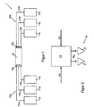
- FIGS. 1 to 4 show an embodiment of a web-fed printing press 1.
- the web-fed printing machine 1 has a first printing section 10a, a second printing section 10b, a turning unit 20 and a folding device 30 (see Fig.1 and Fig.2 ) on.
- the first printing section 10a has a plurality of printing units 11a configured as 8-arm towers (in FIG Fig.1 By way of example, three printing units 11 a are shown) for printing respective printing substrate webs 12 a, 13 a, 14 a.
- the first printing section 10a further comprises for each printing material web 12a-14a on a longitudinal cutting device 15a, which in the web run after the respective printing units 11a and according to this embodiment at the inlet (see Fig.1 ) of the turning unit 20 are arranged.
- the printing material webs 12a-14a of the first printing section 10a leave the printing units 11a of the first printing section 10a in vertical alignment and are rotated by respective deflection rollers (not shown) into a horizontally extending, first web running direction R1 deflected, in which the printing material webs 12a-14a run into the turning unit 20.
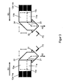
- Each of the longitudinal cutting devices 15a of the first printing section 10a is set up in such a way that the respective printing material web 12a-14a extends longitudinally into a 1/3-wide partial web T1a and a 2/3-wide partial web T2a (see FIG Figure 3 ) is divisible.
- each of the longitudinal cutting devices 15a of the first printing section 10a is bidirectional (as indicated by the double arrow in FIG. 1) transversely to the first web running direction R1 (parallel to a second web running direction R2) Figure 3 indicated) movable, so that it is adjustable to different web widths of the printing material web 12a-14a corresponding, predetermined cutting positions.
- the turning unit 20 has a plurality of turning bar arrangements for the respective printing substrate webs 12a-14a of the first printing line 10a.
- the turning bar arrangement for one of the printing material webs 12a-14a of the first printing section 10a will be described below, wherein the described turning bar arrangement is to be transferred to the turning bar arrangements for the other printing material webs 12a-14a of the first printing section 10a ,
- the turning bar arrangements for the first printing line 10a each have a first turning bar 21 for the 1/3 width partial web T1a and a second turning bar 22 for the 2/3 wide partial web T2a of a respective printing material web 12a-14a of the first printing line 10a on.
- the two turning bars 21, 22 are arranged parallel to each other, so that in the printing operation over this the 1/3 width partial web T1 a and the 2/3 width partial web T2a are rotated by 90 degrees in the same direction in the second web running direction R2.
- first turning bar 21 and the second turning bar 22 are each individually or jointly parallel to the first web running direction R1 and parallel to the second web running direction R2 bidirectionally (as indicated by the double arrows in Figure 3 indicated) movable.
- the folding device 30 has two in the second direction of web travel R2 arranged after the turning unit 20 formers 31 and 32.
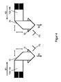
- the in the Figures 2-4 Folding funnel 31 shown on the left serves for the simultaneous processing of the 1/3-wide partial webs T1 a and the 2/3-wide partial webs T2a to 3-sided products P3 (see Figure 3 ) and for processing the undivided printing substrate webs 12a-14a to 2-side products P2 (see Figure 4 ).
- the in the Figures 2-4 Folding funnel 32 shown on the right is associated with the second pressure path 10b.
- the second printing section 10b has a plurality of printing units 11b (in FIG Fig.1 By way of example, three printing units 11b are shown) for printing respective printing substrate webs 12b, 13b, 14b.
- the second printing section 10b also has, for each printing material web 12b-14b, a longitudinal cutting device 15b which, in the web run, follows the respective printing units 11b and, according to this embodiment, the inlet (see FIG Fig.1 ) of the turning unit 20 are arranged.
- the printing material webs 12b-14b of the second printing section 10b leave the printing units 11b of the second printing section 10b in vertical alignment and are deflected by respective deflection rollers (not shown) into a horizontally extending, third web running direction R3, in which the printing substrate webs 12b-14b in FIG enter the turning unit 20.
- the third web running direction R3 runs parallel and opposite to the first web running direction R1.
- Each of the longitudinal cutting devices 15b of the second printing section 10b is set up in such a way that the respective printing material web 12b-14b is longitudinally in a 1/3 width Partial track T1b and a 2/3-wide partial track T2b (see Figure 3 ) is divisible.
- each of the longitudinal cutting devices 15b of the second printing section 10b is bidirectional (as indicated by the double arrow in FIG. 1) transversely to the third web running direction R3 (parallel to the second web running direction R2) Figure 3 indicated) movable, so that it is adjustable to different web widths of the printing substrate 12b-14b respectively corresponding, predetermined cutting positions.
- the turning unit 20 has a plurality of turning bar arrangements for the respective printing substrate webs 12b-14b of the second printing section 10b.
- the turning bar arrangement for one of the printing material webs 12b-14b of the second printing section 10b will be described below, wherein the described turning bar arrangement can be thoughtfully transferred to the turning bar arrangements for the other printing material webs 12b-14b of the second printing section 10b ,
- the turning bar arrangements for the second printing section 10b each have a third turning bar 23 for the 1/3 width partial web T1b and a fourth turning bar 24 for the 2/3 wide dividing line T2b of a respective printing material web 12b-14b of the second printing line 10b on.
- the two turning bars 23, 24 are arranged parallel to each other, so that in the printing operation over this the 1/3-width partial web T1 b and the 2/3-wide partial web T2b are rotated by 90 degrees in the same direction in the second web running direction R2.
- the third turning bar 23 and the fourth turning bar 24 are each bidirectionally individually or jointly parallel to the third web running direction R3 and parallel to the second web running direction R2 (as indicated by the double arrows in FIG Figure 3 indicated) movable.
- Folding funnel 32 shown on the right is used for the simultaneous processing of the 1/3-wide partial webs T1 b and the 2/3-wide partial webs T2b 3-sided products P3 (see Figure 3 ) and for processing the undivided printing substrate webs 12b-14b into 2-side products P2 (see Figure 4 ).
- FIGS. 1 to 4 exemplarily explained two possible operating variants of the web printing machine according to the invention in its basic features.
- the operation of the web-fed printing press 1 for producing a 3-sided product P3 is described only for the first printing line 10a and one of the printing material webs 12a-14a, the processes being thought of on the other printing material webs 12a-14a of the first printing line 10a or on the second printing section 10b are to be transmitted.
- the printed pages 11a In operation of the web-fed printing machine 1 for producing a 3-sided product P3, the printed pages 11a, whose plate cylinders are three standing or lying along their bale width in the printing unit 11a in the e.g. Tabloid format or in broadsheet format have arranged one behind the other, printed substrate web 12a-14a in the first web running direction R1 in the turning unit 20 led into it.
- the printing material web 12a-14a is cut longitudinally into a 1/3 width partial web T1a and a 2/3 width partial web T2a (see FIG Figure 3 ).
- the 1/3-wide partial web T1a is turned in its web running direction over the first turning bar 21 of the turning unit 20 by 90 degrees and the 2/3-width partial web T2a in its web running direction via a second turning bar 22nd the turning unit 20 turned by 90 degrees, so that both partial webs T1 a and T2a run in the second direction of web travel R2.
- both partial webs T1a, T2a are guided over the left former 31 for producing 3-side products P3.
- the second turning bar 22 is set so that the 2/3-width partial web T2a runs centered on the hopper tip on the left former 31, and the first turner bar 21 is set so that the 1/3 width partial web T1a with a side edge fits to the hopper tip on the former 31.
- a 3-sided product P3 can be produced, in which between two contiguous, longitudinally folded printed pages (the 2/3-wide partial web T2a) a single printed page (the 1/3-width partial web T1a) is arranged.
- the operation of the web-fed printing press 1 for producing a 2-page product P2 is described only for the first printing line 10a and one of the printing material webs 12a-14a, wherein the processes mentally on the other printing material webs 12a-14a of the first printing section 10a and on the second printing section 10b are to be transmitted.
- the printing substrate 12a-14a in the first web running direction R1 is printed in one of the printing units 11a, whose plate cylinders have two printing pages standing or lying along their bale width, eg in tabloid format or in broadsheet format introduced into the turning unit 20, wherein the longitudinal cutter 15a is put out of operation.
- the undivided printing material web 12a-14a is then turned and aligned by means of the second turning bar 22 (which has been moved accordingly) so that the undivided printing material web 12a-14a runs onto the former 31 in the middle of its hopper tip.
- a 2-sided product P2 can be produced, in which two contiguous printed pages are longitudinally folded in the middle.
Landscapes
- Engineering & Computer Science (AREA)
- Mechanical Engineering (AREA)
- Folding Of Thin Sheet-Like Materials, Special Discharging Devices, And Others (AREA)
- Rotary Presses (AREA)
Claims (6)
- Machine d'impression rotative (1), présentant :un parcours d'impression (10a) comportant :au moins une unité d'impression (11a) pour imprimer une bande de support d'impression (12a, 13a, 14a) etun dispositif de coupe longitudinale (15a) qui est disposé dans le parcours de la bande en aval decette unité d'impression (11a) et qui est conçu pour permettre de diviser ou de ne pas diviser labande de support d'impression (12a, 13a, 14a) en longueur en une sous-bande large de 1/3 (T1a) etune sous-bande large de 2/3 (T2a) en fonction de l'application de pression,une unité de retournement (20) dans laquelle la sous-bande large de 1/3 (T1a) et la sous-bande large de 2/3 (T2a) ou la bande de support d'impression (12a, 13a, 14a) non divisée doivent être introduites dans un premier sens de circulation de la bande (R1) et qui présente une première barre de retournement (21) pour la sous-bande large de 1/3 (T1a) et une deuxième barre de retournement pour la sous-bande large de 2/3 (T2a) ou la bande de support d'impression (12a, 13a,14a) non divisée,les deux barres de retournement (21, 22) étant disposées parallèlement l'une à l'autre, de manière à ce que grâce à celles-ci, les sous-bandes larges de 1/3 (T1a) et de 2/3 (T1a, T2a) oula bande de support d'impression (12a, 13a, 14a) non divisée puissent être retournées de 90 degrés dans le même sens de circulation dans un deuxième sens de circulation de bande (R2), les première etdeuxième tiges de retournement (21, 22) étant respectivement déplaçables individuellement ou en commun parallèlement au premier (R1) et/ou deuxième (R2) sens de circulation de la bandeet le dispositif de coupe longitudinale (15a) étant déplaçable parallèlement au deuxième sens de circulation de la bande, de manière à être réglable à des positions de coupe prédéfinies correspondant respectivement à différentes largeurs de bande de la bande de support d'impression (12a, 13a, 14a),et au moins un cône de pliage (31) disposé dans le deuxième sens de circulation de la bande (R2) en aval de l'unité de retournement (20) pour transformer simultanément la sous-bande large de 1/3 (T1a) et la sous-bande large de 2/3 (T2a) en produits à 3 faces (P3) et pour transformer la bande de support d'impression (12a, 13a, 14a) non divisée en produits à 2 faces (P2).
- Machine d'impression rotative (1) selon la revendication 1, présentant en outre :un deuxième parcours d'impression (10b) comportant :au moins une unité d'impression (11b) pour imprimer une bande de support d'impression (12b, 13b, 14b) etun dispositif de coupe longitudinale (15b) qui est disposé dans le parcours de circulation de la bande en aval de l'unité d'impression (11b) du deuxième parcours d'impression (10b) et qui est conçu pour permettre de diviser ou de ne pas diviser la bande de support d'impression (12b, 13b, 14b) du deuxième parcours d'impression (10b) en longueur en une sous-bande large de 1/3 (T1b) et une sous-bande large de 2/3 (T2b) en fonction de l'application de pression,l'unité de retournement (20) étant disposée entre les unités d'impression respectives (11a, 11b) des premier et deuxième parcours d'impression (10a, 10b) et la sous-bande large de 1/3 (T1b) et la sous-bande large de 2/3 (T2b) du deuxième parcours d'impression (10b) devant être introduites dans un troisième sens de circulation de la bande (R3) qui est orienté parallèlement et à l'inverse du premier sens de circulation de la bande (R1) dans l'unité de retournement (20), l'unité de retournement (20) présentant une troisième barre de retournement (23) pour la sous-bande large de 1/3 (T1b) et une quatrième barre de retournement (24) pour la sous-bande large de 2/3 (T2b) du deuxième parcours d'impression (10b) ou la bande de support d'impression (12a, 13a, 14a) non divisée,les troisième et quatrième barres de retournement (23, 24) étant disposées parallèlement l'une à l'autre, de manière à ce que grâce à celles-ci,les sous-bandes larges de 1/3 et de 2/3 (T1b, T2b) ou la bande de support d'impression (12a, 13a,14a) non divisée du deuxième parcours d'impression (10b) puissent être retournées de 90 degrés dans le même sens de circulation pour aller dans le deuxième sens de circulation de la bande (R2),au moins un cône de pliage (32) disposé dans le deuxième sens de circulation de la bande (R2) en aval de l'unité de retournement (20) pour transformer simultanément les sous-bandes larges de 1/3 et 2/3 (T1b, T2b) en produits à 3 faces (P3) et pour transformer la bande de support d'impression (12b, 13b, 14b) non divisée du deuxième parcours d'impression (10b) en produits à 2 faces (P2).
- Machine d'impression rotative (1) selon la revendication 2, dans laquelle le dispositif de coupe longitudinale (15b) du deuxième parcours d'impression (10b) est déplaçable parallèlement au deuxième sens de circulation de la bande (R2) de manière à être réglable à des positions de coupe prédéfinies correspondant respectivement à différentes largeurs de bande de la bande de support d'impression (12b, 13b, 14b) du deuxième parcours d'impression (10b).
- Machine d'impression rotative (1) selon la revendication 3, dans laquelle les troisième et quatrième barres de retournement (23, 24) sont respectivement déplaçables individuellement ou ensemble parallèlement au troisième sens de circulation de la bande (R3).
- Machine d'impression rotative (1) selon la revendication 3 ou 4, dans laquelle les troisième et quatrième barres de retournement (23, 24) sont respectivement déplaçables individuellement ou ensemble parallèlement au deuxième sens de circulation de la bande (R2).
- Procédé de fabrication d'un produit d'impression sur une machine d'impression rotative (1) selon la revendication 1, dans laquelle
une bande de support d'impression (12a, 13a, 14a ; 12b, 13b, 14b) imprimée dans au moins une unité d'impression (11a, 11b) de la machine d'impression rotative (1) est introduite dans une unité de retournement (20) de la machine d'impression rotative (1),
la bande de support d'impression (12a, 13a, 14a ; 12b, 13b, 14b) est divisée en longueur en une sous-bande large de 1/3 (T1a, T1b) et une sous-bande large de 2/3 (T2a, T2b),
des barres de retournement (21, 22, 23, 24) de l'unité de retournement sont déplaçables et réglées en fonction des sous-bandes (T1a, T1b, T2a, T2b),
la sous-bande large de 1/3 (T1a, T1b) est tournée de 90 degrés dans son sens de circulation de bande (R1 ; R3) à l'aide d'une barre de retournement (21, 23) de l'unité de retournement (20),
la sous-bande large de 2/3 (T2a ; T2b), est tournée de 90 degrés dans son sens de circulation de bande (R1 ; R3) à l'aide d'une autre barre de retournement (22, 24) de l'unité de retournement (20), de sorte que les sens de circulation de bande (R2) des deux sous-bandes (T1a ; T1b, T2a ; T2b) sont identiques et
les deux sous-bandes (T1a ; T1b, T2a ; T2b), après retournement, sont guidées via au moins un cône de plage (31, 32) pour fabriquer des produits à 3 faces (P3).
Applications Claiming Priority (1)
| Application Number | Priority Date | Filing Date | Title |
|---|---|---|---|
| DE200810035675 DE102008035675A1 (de) | 2008-07-30 | 2008-07-30 | Rollendruckmaschine und Verfahren zum Herstellen eines Druckproduktes auf der Rollendruckmaschine |
Publications (3)
| Publication Number | Publication Date |
|---|---|
| EP2149452A2 EP2149452A2 (fr) | 2010-02-03 |
| EP2149452A3 EP2149452A3 (fr) | 2011-11-02 |
| EP2149452B1 true EP2149452B1 (fr) | 2014-10-22 |
Family
ID=41170076
Family Applications (1)
| Application Number | Title | Priority Date | Filing Date |
|---|---|---|---|
| EP20090166471 Not-in-force EP2149452B1 (fr) | 2008-07-30 | 2009-07-27 | Presse à rouleaux et procédé de fabrication d'un produit d'impression sur la presse à rouleaux |
Country Status (2)
| Country | Link |
|---|---|
| EP (1) | EP2149452B1 (fr) |
| DE (1) | DE102008035675A1 (fr) |
Family Cites Families (2)
| Publication number | Priority date | Publication date | Assignee | Title |
|---|---|---|---|---|
| DE102004001399A1 (de) * | 2004-01-09 | 2005-08-04 | Koenig & Bauer Ag | Druckmaschine |
| DE102005034331B4 (de) * | 2005-04-13 | 2009-04-09 | Koenig & Bauer Aktiengesellschaft | Rollenrotationsdruckmaschine |
-
2008
- 2008-07-30 DE DE200810035675 patent/DE102008035675A1/de not_active Withdrawn
-
2009
- 2009-07-27 EP EP20090166471 patent/EP2149452B1/fr not_active Not-in-force
Also Published As
| Publication number | Publication date |
|---|---|
| DE102008035675A1 (de) | 2013-02-28 |
| EP2149452A2 (fr) | 2010-02-03 |
| EP2149452A3 (fr) | 2011-11-02 |
Similar Documents
| Publication | Publication Date | Title |
|---|---|---|
| EP1990190B1 (fr) | Presse rotative à bandes | |
| EP0107126A1 (fr) | Dispositif de guidage de la bande de papier dans une rotative d'impression | |
| EP1072551A2 (fr) | Ensemble d'une machine de pliage dans une machine à imprimer rotative pour journaux | |
| EP1106554A2 (fr) | Plieuse mobile et arrangement de triangle plieur | |
| DE4327646C2 (de) | Breiten-Einstellverfahren für eine Papierbahn sowie damit ausgerüstete lithographische Rotationspresse | |
| EP1634833B1 (fr) | Machine à imprimer comprenant au moins un groupe d'impression. | |
| DE102005034331B4 (de) | Rollenrotationsdruckmaschine | |
| EP1456107B1 (fr) | Dispositif de production de produits plies | |
| EP0957057B1 (fr) | Dispositif de pliage longitudinal pour l'appareil de pliage de machines d'impression rotatives | |
| EP2193918B1 (fr) | Agencement de cône plieur | |
| EP2223806A1 (fr) | Dispositif et procédé d'écartement de bandes se déroulant dans le sens transversal par rapport à l'axe longitudinal d'une presse d'impression rotative | |
| EP2149452B1 (fr) | Presse à rouleaux et procédé de fabrication d'un produit d'impression sur la presse à rouleaux | |
| EP2020292A2 (fr) | Presse rotative à rouleaux | |
| DE102007030844A1 (de) | Rollenrotationsdruckmaschine, insbesondere Tiefdruckmaschine, mit halbbreiter Bedruckstoffbahn | |
| EP1718463B1 (fr) | Machine a imprimer a cone plieur | |
| DE102008005392A1 (de) | Bahnspreizeinrichtung für eine Rotationsdruckmaschine und damit ausgerüstete Rotationsdruckmaschine | |
| DE10163211C2 (de) | Vorrichtung zur Herstellung von Falzprodukten | |
| DE102011088783B4 (de) | Rollen-Rotationsdruckmaschine | |
| DE102008054367A1 (de) | Falztrichteranordnung | |
| EP1992485A2 (fr) | Presse rotative et un procédé de production d'un produit d'impression | |
| EP2030933A2 (fr) | Procédé destiné au fonctionnement d'une imprimante rotative à rouleaux | |
| DE102011088780B4 (de) | Rollen-Rotationsdruckmaschine | |
| DE102016216429B4 (de) | Druckprodukt, Verfahren und Rollendruckmaschine zur Herstellung eines Druckproduktes | |
| DE102008034982B4 (de) | Falzrichteranordnung für eine Rollendruckmaschine | |
| EP2202191B1 (fr) | Presse rotative à rouleaux et un procédé de production d'un produit d'impression |
Legal Events
| Date | Code | Title | Description |
|---|---|---|---|
| PUAI | Public reference made under article 153(3) epc to a published international application that has entered the european phase |
Free format text: ORIGINAL CODE: 0009012 |
|
| AK | Designated contracting states |
Kind code of ref document: A2 Designated state(s): AT BE BG CH CY CZ DE DK EE ES FI FR GB GR HR HU IE IS IT LI LT LU LV MC MK MT NL NO PL PT RO SE SI SK SM TR |
|
| AX | Request for extension of the european patent |
Extension state: AL BA RS |
|
| PUAL | Search report despatched |
Free format text: ORIGINAL CODE: 0009013 |
|
| AK | Designated contracting states |
Kind code of ref document: A3 Designated state(s): AT BE BG CH CY CZ DE DK EE ES FI FR GB GR HR HU IE IS IT LI LT LU LV MC MK MT NL NO PL PT RO SE SI SK SM TR |
|
| AX | Request for extension of the european patent |
Extension state: AL BA RS |
|
| RIC1 | Information provided on ipc code assigned before grant |
Ipc: B65H 45/28 20060101ALI20110926BHEP Ipc: B41F 13/58 20060101AFI20110926BHEP |
|
| 19U | Interruption of proceedings before grant |
Effective date: 20120201 |
|
| 19W | Proceedings resumed before grant after interruption of proceedings |
Effective date: 20130603 |
|
| RAP1 | Party data changed (applicant data changed or rights of an application transferred) |
Owner name: MANROLAND WEB SYSTEMS GMBH |
|
| 17P | Request for examination filed |
Effective date: 20130713 |
|
| RBV | Designated contracting states (corrected) |
Designated state(s): AT BE BG CH CY CZ DE DK EE ES FI FR GB GR HR HU IE IS IT LI LT LU LV MC MK MT NL NO PL PT RO SE SI SK SM TR |
|
| 17Q | First examination report despatched |
Effective date: 20130920 |
|
| GRAP | Despatch of communication of intention to grant a patent |
Free format text: ORIGINAL CODE: EPIDOSNIGR1 |
|
| INTG | Intention to grant announced |
Effective date: 20140717 |
|
| GRAS | Grant fee paid |
Free format text: ORIGINAL CODE: EPIDOSNIGR3 |
|
| GRAA | (expected) grant |
Free format text: ORIGINAL CODE: 0009210 |
|
| AK | Designated contracting states |
Kind code of ref document: B1 Designated state(s): AT BE BG CH CY CZ DE DK EE ES FI FR GB GR HR HU IE IS IT LI LT LU LV MC MK MT NL NO PL PT RO SE SI SK SM TR |
|
| REG | Reference to a national code |
Ref country code: GB Ref legal event code: FG4D Free format text: NOT ENGLISH |
|
| REG | Reference to a national code |
Ref country code: CH Ref legal event code: EP Ref country code: CH Ref legal event code: NV Representative=s name: E. BLUM AND CO. AG PATENT- UND MARKENANWAELTE , CH |
|
| REG | Reference to a national code |
Ref country code: AT Ref legal event code: REF Ref document number: 692412 Country of ref document: AT Kind code of ref document: T Effective date: 20141115 |
|
| REG | Reference to a national code |
Ref country code: IE Ref legal event code: FG4D Free format text: LANGUAGE OF EP DOCUMENT: GERMAN |
|
| REG | Reference to a national code |
Ref country code: DE Ref legal event code: R096 Ref document number: 502009010122 Country of ref document: DE Effective date: 20141204 |
|
| REG | Reference to a national code |
Ref country code: NL Ref legal event code: T3 |
|
| REG | Reference to a national code |
Ref country code: LT Ref legal event code: MG4D |
|
| PG25 | Lapsed in a contracting state [announced via postgrant information from national office to epo] |
Ref country code: PT Free format text: LAPSE BECAUSE OF FAILURE TO SUBMIT A TRANSLATION OF THE DESCRIPTION OR TO PAY THE FEE WITHIN THE PRESCRIBED TIME-LIMIT Effective date: 20150223 Ref country code: LT Free format text: LAPSE BECAUSE OF FAILURE TO SUBMIT A TRANSLATION OF THE DESCRIPTION OR TO PAY THE FEE WITHIN THE PRESCRIBED TIME-LIMIT Effective date: 20141022 Ref country code: NO Free format text: LAPSE BECAUSE OF FAILURE TO SUBMIT A TRANSLATION OF THE DESCRIPTION OR TO PAY THE FEE WITHIN THE PRESCRIBED TIME-LIMIT Effective date: 20150122 Ref country code: ES Free format text: LAPSE BECAUSE OF FAILURE TO SUBMIT A TRANSLATION OF THE DESCRIPTION OR TO PAY THE FEE WITHIN THE PRESCRIBED TIME-LIMIT Effective date: 20141022 Ref country code: IS Free format text: LAPSE BECAUSE OF FAILURE TO SUBMIT A TRANSLATION OF THE DESCRIPTION OR TO PAY THE FEE WITHIN THE PRESCRIBED TIME-LIMIT Effective date: 20150222 Ref country code: FI Free format text: LAPSE BECAUSE OF FAILURE TO SUBMIT A TRANSLATION OF THE DESCRIPTION OR TO PAY THE FEE WITHIN THE PRESCRIBED TIME-LIMIT Effective date: 20141022 |
|
| PG25 | Lapsed in a contracting state [announced via postgrant information from national office to epo] |
Ref country code: SE Free format text: LAPSE BECAUSE OF FAILURE TO SUBMIT A TRANSLATION OF THE DESCRIPTION OR TO PAY THE FEE WITHIN THE PRESCRIBED TIME-LIMIT Effective date: 20141022 Ref country code: HR Free format text: LAPSE BECAUSE OF FAILURE TO SUBMIT A TRANSLATION OF THE DESCRIPTION OR TO PAY THE FEE WITHIN THE PRESCRIBED TIME-LIMIT Effective date: 20141022 Ref country code: CY Free format text: LAPSE BECAUSE OF FAILURE TO SUBMIT A TRANSLATION OF THE DESCRIPTION OR TO PAY THE FEE WITHIN THE PRESCRIBED TIME-LIMIT Effective date: 20141022 Ref country code: PL Free format text: LAPSE BECAUSE OF FAILURE TO SUBMIT A TRANSLATION OF THE DESCRIPTION OR TO PAY THE FEE WITHIN THE PRESCRIBED TIME-LIMIT Effective date: 20141022 Ref country code: LV Free format text: LAPSE BECAUSE OF FAILURE TO SUBMIT A TRANSLATION OF THE DESCRIPTION OR TO PAY THE FEE WITHIN THE PRESCRIBED TIME-LIMIT Effective date: 20141022 Ref country code: GR Free format text: LAPSE BECAUSE OF FAILURE TO SUBMIT A TRANSLATION OF THE DESCRIPTION OR TO PAY THE FEE WITHIN THE PRESCRIBED TIME-LIMIT Effective date: 20150123 |
|
| REG | Reference to a national code |
Ref country code: DE Ref legal event code: R097 Ref document number: 502009010122 Country of ref document: DE |
|
| PG25 | Lapsed in a contracting state [announced via postgrant information from national office to epo] |
Ref country code: EE Free format text: LAPSE BECAUSE OF FAILURE TO SUBMIT A TRANSLATION OF THE DESCRIPTION OR TO PAY THE FEE WITHIN THE PRESCRIBED TIME-LIMIT Effective date: 20141022 Ref country code: SK Free format text: LAPSE BECAUSE OF FAILURE TO SUBMIT A TRANSLATION OF THE DESCRIPTION OR TO PAY THE FEE WITHIN THE PRESCRIBED TIME-LIMIT Effective date: 20141022 Ref country code: DK Free format text: LAPSE BECAUSE OF FAILURE TO SUBMIT A TRANSLATION OF THE DESCRIPTION OR TO PAY THE FEE WITHIN THE PRESCRIBED TIME-LIMIT Effective date: 20141022 Ref country code: CZ Free format text: LAPSE BECAUSE OF FAILURE TO SUBMIT A TRANSLATION OF THE DESCRIPTION OR TO PAY THE FEE WITHIN THE PRESCRIBED TIME-LIMIT Effective date: 20141022 Ref country code: RO Free format text: LAPSE BECAUSE OF FAILURE TO SUBMIT A TRANSLATION OF THE DESCRIPTION OR TO PAY THE FEE WITHIN THE PRESCRIBED TIME-LIMIT Effective date: 20141022 |
|
| PLBE | No opposition filed within time limit |
Free format text: ORIGINAL CODE: 0009261 |
|
| STAA | Information on the status of an ep patent application or granted ep patent |
Free format text: STATUS: NO OPPOSITION FILED WITHIN TIME LIMIT |
|
| PG25 | Lapsed in a contracting state [announced via postgrant information from national office to epo] |
Ref country code: IT Free format text: LAPSE BECAUSE OF FAILURE TO SUBMIT A TRANSLATION OF THE DESCRIPTION OR TO PAY THE FEE WITHIN THE PRESCRIBED TIME-LIMIT Effective date: 20141022 |
|
| 26N | No opposition filed |
Effective date: 20150723 |
|
| PG25 | Lapsed in a contracting state [announced via postgrant information from national office to epo] |
Ref country code: MC Free format text: LAPSE BECAUSE OF FAILURE TO SUBMIT A TRANSLATION OF THE DESCRIPTION OR TO PAY THE FEE WITHIN THE PRESCRIBED TIME-LIMIT Effective date: 20141022 Ref country code: SI Free format text: LAPSE BECAUSE OF FAILURE TO SUBMIT A TRANSLATION OF THE DESCRIPTION OR TO PAY THE FEE WITHIN THE PRESCRIBED TIME-LIMIT Effective date: 20141022 |
|
| GBPC | Gb: european patent ceased through non-payment of renewal fee |
Effective date: 20150727 |
|
| PG25 | Lapsed in a contracting state [announced via postgrant information from national office to epo] |
Ref country code: LU Free format text: LAPSE BECAUSE OF FAILURE TO SUBMIT A TRANSLATION OF THE DESCRIPTION OR TO PAY THE FEE WITHIN THE PRESCRIBED TIME-LIMIT Effective date: 20150727 |
|
| REG | Reference to a national code |
Ref country code: IE Ref legal event code: MM4A |
|
| PG25 | Lapsed in a contracting state [announced via postgrant information from national office to epo] |
Ref country code: GB Free format text: LAPSE BECAUSE OF NON-PAYMENT OF DUE FEES Effective date: 20150727 |
|
| REG | Reference to a national code |
Ref country code: FR Ref legal event code: PLFP Year of fee payment: 8 |
|
| PG25 | Lapsed in a contracting state [announced via postgrant information from national office to epo] |
Ref country code: IE Free format text: LAPSE BECAUSE OF NON-PAYMENT OF DUE FEES Effective date: 20150727 |
|
| REG | Reference to a national code |
Ref country code: AT Ref legal event code: MM01 Ref document number: 692412 Country of ref document: AT Kind code of ref document: T Effective date: 20150727 |
|
| PG25 | Lapsed in a contracting state [announced via postgrant information from national office to epo] |
Ref country code: AT Free format text: LAPSE BECAUSE OF NON-PAYMENT OF DUE FEES Effective date: 20150727 |
|
| PG25 | Lapsed in a contracting state [announced via postgrant information from national office to epo] |
Ref country code: MT Free format text: LAPSE BECAUSE OF FAILURE TO SUBMIT A TRANSLATION OF THE DESCRIPTION OR TO PAY THE FEE WITHIN THE PRESCRIBED TIME-LIMIT Effective date: 20141022 |
|
| PG25 | Lapsed in a contracting state [announced via postgrant information from national office to epo] |
Ref country code: SM Free format text: LAPSE BECAUSE OF FAILURE TO SUBMIT A TRANSLATION OF THE DESCRIPTION OR TO PAY THE FEE WITHIN THE PRESCRIBED TIME-LIMIT Effective date: 20141022 Ref country code: HU Free format text: LAPSE BECAUSE OF FAILURE TO SUBMIT A TRANSLATION OF THE DESCRIPTION OR TO PAY THE FEE WITHIN THE PRESCRIBED TIME-LIMIT; INVALID AB INITIO Effective date: 20090727 Ref country code: BG Free format text: LAPSE BECAUSE OF FAILURE TO SUBMIT A TRANSLATION OF THE DESCRIPTION OR TO PAY THE FEE WITHIN THE PRESCRIBED TIME-LIMIT Effective date: 20141022 |
|
| REG | Reference to a national code |
Ref country code: FR Ref legal event code: PLFP Year of fee payment: 9 |
|
| PG25 | Lapsed in a contracting state [announced via postgrant information from national office to epo] |
Ref country code: BE Free format text: LAPSE BECAUSE OF NON-PAYMENT OF DUE FEES Effective date: 20150731 |
|
| PG25 | Lapsed in a contracting state [announced via postgrant information from national office to epo] |
Ref country code: TR Free format text: LAPSE BECAUSE OF FAILURE TO SUBMIT A TRANSLATION OF THE DESCRIPTION OR TO PAY THE FEE WITHIN THE PRESCRIBED TIME-LIMIT Effective date: 20141022 |
|
| PG25 | Lapsed in a contracting state [announced via postgrant information from national office to epo] |
Ref country code: MK Free format text: LAPSE BECAUSE OF FAILURE TO SUBMIT A TRANSLATION OF THE DESCRIPTION OR TO PAY THE FEE WITHIN THE PRESCRIBED TIME-LIMIT Effective date: 20141022 |
|
| REG | Reference to a national code |
Ref country code: FR Ref legal event code: PLFP Year of fee payment: 10 |
|
| PGFP | Annual fee paid to national office [announced via postgrant information from national office to epo] |
Ref country code: DE Payment date: 20180723 Year of fee payment: 10 Ref country code: NL Payment date: 20180719 Year of fee payment: 10 Ref country code: FR Payment date: 20180725 Year of fee payment: 10 |
|
| REG | Reference to a national code |
Ref country code: DE Ref legal event code: R081 Ref document number: 502009010122 Country of ref document: DE Owner name: MANROLAND GOSS WEB SYSTEMS GMBH, DE Free format text: FORMER OWNER: MANROLAND WEB SYSTEMS GMBH, 86153 AUGSBURG, DE |
|
| PGFP | Annual fee paid to national office [announced via postgrant information from national office to epo] |
Ref country code: CH Payment date: 20180719 Year of fee payment: 10 |
|
| REG | Reference to a national code |
Ref country code: DE Ref legal event code: R119 Ref document number: 502009010122 Country of ref document: DE |
|
| REG | Reference to a national code |
Ref country code: CH Ref legal event code: PL |
|
| PG25 | Lapsed in a contracting state [announced via postgrant information from national office to epo] |
Ref country code: NL Free format text: LAPSE BECAUSE OF NON-PAYMENT OF DUE FEES Effective date: 20190801 Ref country code: DE Free format text: LAPSE BECAUSE OF NON-PAYMENT OF DUE FEES Effective date: 20200201 |
|
| REG | Reference to a national code |
Ref country code: NL Ref legal event code: MM Effective date: 20190801 |
|
| PG25 | Lapsed in a contracting state [announced via postgrant information from national office to epo] |
Ref country code: LI Free format text: LAPSE BECAUSE OF NON-PAYMENT OF DUE FEES Effective date: 20190731 Ref country code: CH Free format text: LAPSE BECAUSE OF NON-PAYMENT OF DUE FEES Effective date: 20190731 |
|
| PG25 | Lapsed in a contracting state [announced via postgrant information from national office to epo] |
Ref country code: FR Free format text: LAPSE BECAUSE OF NON-PAYMENT OF DUE FEES Effective date: 20190731 |