EP2149610B1 - Vorrichtung zum nachweis genetischen materials mittels polymerasekettenreaktion - Google Patents
Vorrichtung zum nachweis genetischen materials mittels polymerasekettenreaktion Download PDFInfo
- Publication number
- EP2149610B1 EP2149610B1 EP07730404.6A EP07730404A EP2149610B1 EP 2149610 B1 EP2149610 B1 EP 2149610B1 EP 07730404 A EP07730404 A EP 07730404A EP 2149610 B1 EP2149610 B1 EP 2149610B1
- Authority
- EP
- European Patent Office
- Prior art keywords
- reaction chamber
- substrate
- chamber
- heating
- micro
- Prior art date
- Legal status (The legal status is an assumption and is not a legal conclusion. Google has not performed a legal analysis and makes no representation as to the accuracy of the status listed.)
- Not-in-force
Links
Images








Classifications
-
- B—PERFORMING OPERATIONS; TRANSPORTING
- B01—PHYSICAL OR CHEMICAL PROCESSES OR APPARATUS IN GENERAL
- B01L—CHEMICAL OR PHYSICAL LABORATORY APPARATUS FOR GENERAL USE
- B01L7/00—Heating or cooling apparatus; Heat insulating devices
- B01L7/52—Heating or cooling apparatus; Heat insulating devices with provision for submitting samples to a predetermined sequence of different temperatures, e.g. for treating nucleic acid samples
-
- B—PERFORMING OPERATIONS; TRANSPORTING
- B01—PHYSICAL OR CHEMICAL PROCESSES OR APPARATUS IN GENERAL
- B01L—CHEMICAL OR PHYSICAL LABORATORY APPARATUS FOR GENERAL USE
- B01L3/00—Containers or dishes for laboratory use, e.g. laboratory glassware; Droppers
- B01L3/50—Containers for the purpose of retaining a material to be analysed, e.g. test tubes
- B01L3/502—Containers for the purpose of retaining a material to be analysed, e.g. test tubes with fluid transport, e.g. in multi-compartment structures
- B01L3/5027—Containers for the purpose of retaining a material to be analysed, e.g. test tubes with fluid transport, e.g. in multi-compartment structures by integrated microfluidic structures, i.e. dimensions of channels and chambers are such that surface tension forces are important, e.g. lab-on-a-chip
- B01L3/502761—Containers for the purpose of retaining a material to be analysed, e.g. test tubes with fluid transport, e.g. in multi-compartment structures by integrated microfluidic structures, i.e. dimensions of channels and chambers are such that surface tension forces are important, e.g. lab-on-a-chip specially adapted for handling suspended solids or molecules independently from the bulk fluid flow, e.g. for trapping or sorting beads or physically stretching molecules
-
- B—PERFORMING OPERATIONS; TRANSPORTING
- B01—PHYSICAL OR CHEMICAL PROCESSES OR APPARATUS IN GENERAL
- B01L—CHEMICAL OR PHYSICAL LABORATORY APPARATUS FOR GENERAL USE
- B01L2200/00—Solutions for specific problems relating to chemical or physical laboratory apparatus
- B01L2200/02—Adapting objects or devices to another
- B01L2200/026—Fluid interfacing between devices or objects, e.g. connectors, inlet details
- B01L2200/027—Fluid interfacing between devices or objects, e.g. connectors, inlet details for microfluidic devices
-
- B—PERFORMING OPERATIONS; TRANSPORTING
- B01—PHYSICAL OR CHEMICAL PROCESSES OR APPARATUS IN GENERAL
- B01L—CHEMICAL OR PHYSICAL LABORATORY APPARATUS FOR GENERAL USE
- B01L2200/00—Solutions for specific problems relating to chemical or physical laboratory apparatus
- B01L2200/06—Fluid handling related problems
- B01L2200/0647—Handling flowable solids, e.g. microscopic beads, cells, particles
- B01L2200/0668—Trapping microscopic beads
-
- B—PERFORMING OPERATIONS; TRANSPORTING
- B01—PHYSICAL OR CHEMICAL PROCESSES OR APPARATUS IN GENERAL
- B01L—CHEMICAL OR PHYSICAL LABORATORY APPARATUS FOR GENERAL USE
- B01L2300/00—Additional constructional details
- B01L2300/08—Geometry, shape and general structure
- B01L2300/0809—Geometry, shape and general structure rectangular shaped
- B01L2300/0816—Cards, e.g. flat sample carriers usually with flow in two horizontal directions
-
- B—PERFORMING OPERATIONS; TRANSPORTING
- B01—PHYSICAL OR CHEMICAL PROCESSES OR APPARATUS IN GENERAL
- B01L—CHEMICAL OR PHYSICAL LABORATORY APPARATUS FOR GENERAL USE
- B01L2300/00—Additional constructional details
- B01L2300/14—Means for pressure control
-
- B—PERFORMING OPERATIONS; TRANSPORTING
- B01—PHYSICAL OR CHEMICAL PROCESSES OR APPARATUS IN GENERAL
- B01L—CHEMICAL OR PHYSICAL LABORATORY APPARATUS FOR GENERAL USE
- B01L2300/00—Additional constructional details
- B01L2300/18—Means for temperature control
- B01L2300/1805—Conductive heating, heat from thermostatted solids is conducted to receptacles, e.g. heating plates, blocks
- B01L2300/1827—Conductive heating, heat from thermostatted solids is conducted to receptacles, e.g. heating plates, blocks using resistive heater
-
- B—PERFORMING OPERATIONS; TRANSPORTING
- B01—PHYSICAL OR CHEMICAL PROCESSES OR APPARATUS IN GENERAL
- B01L—CHEMICAL OR PHYSICAL LABORATORY APPARATUS FOR GENERAL USE
- B01L2400/00—Moving or stopping fluids
- B01L2400/04—Moving fluids with specific forces or mechanical means
- B01L2400/0403—Moving fluids with specific forces or mechanical means specific forces
- B01L2400/043—Moving fluids with specific forces or mechanical means specific forces magnetic forces
-
- B—PERFORMING OPERATIONS; TRANSPORTING
- B01—PHYSICAL OR CHEMICAL PROCESSES OR APPARATUS IN GENERAL
- B01L—CHEMICAL OR PHYSICAL LABORATORY APPARATUS FOR GENERAL USE
- B01L2400/00—Moving or stopping fluids
- B01L2400/04—Moving fluids with specific forces or mechanical means
- B01L2400/0475—Moving fluids with specific forces or mechanical means specific mechanical means and fluid pressure
- B01L2400/0487—Moving fluids with specific forces or mechanical means specific mechanical means and fluid pressure fluid pressure, pneumatics
-
- B—PERFORMING OPERATIONS; TRANSPORTING
- B01—PHYSICAL OR CHEMICAL PROCESSES OR APPARATUS IN GENERAL
- B01L—CHEMICAL OR PHYSICAL LABORATORY APPARATUS FOR GENERAL USE
- B01L3/00—Containers or dishes for laboratory use, e.g. laboratory glassware; Droppers
- B01L3/50—Containers for the purpose of retaining a material to be analysed, e.g. test tubes
- B01L3/502—Containers for the purpose of retaining a material to be analysed, e.g. test tubes with fluid transport, e.g. in multi-compartment structures
- B01L3/5027—Containers for the purpose of retaining a material to be analysed, e.g. test tubes with fluid transport, e.g. in multi-compartment structures by integrated microfluidic structures, i.e. dimensions of channels and chambers are such that surface tension forces are important, e.g. lab-on-a-chip
- B01L3/502715—Containers for the purpose of retaining a material to be analysed, e.g. test tubes with fluid transport, e.g. in multi-compartment structures by integrated microfluidic structures, i.e. dimensions of channels and chambers are such that surface tension forces are important, e.g. lab-on-a-chip characterised by interfacing components, e.g. fluidic, electrical, optical or mechanical interfaces
Definitions
- the present invention relates to a method and to a portable device or microdevice to specifically detect genetic material in a biological sample using the technique known as PCR (Polymerase Chain Reaction).
- the microdevice has the object of increasing the efficiency, simplicity of use and the portability of the PCR in comparison with analysis on a laboratory scale.
- the microdevice makes it possible to quickly diagnose the presence of a determined sequence of oligonucleotides (DNA and RNA), by the technique of real-time PCR in a final volume, for example, of 10 microlitres and in less than 30 minutes.
- PCR Polymerase Chain Reaction
- the detection of genetic material is, therefore, based on its amplification, since in the initial sample it is found in very small quantities which cannot be detected, whilst, through PCR reaction, the genetic material starts its amplification until it can be detected (if it is not present in the sample, obviously the detection is not made).
- the PCR reaction in a microdevice is performed in a micro-chamber (within a chip or plastic support) which has a small inlet for the sample and a second orifice for the outlet thereof.
- the devices used are very complex since they comprise several chambers whereby the sample is made to pass to perform the concentration of the target analyte, PCR reaction and detection, which slows down the process.
- the means of heating are typically external to the chamber or plastic support wherein the PCR reaction is produced, and they do not provide a suitable and fast heating in all parts of the chamber where the reaction occurs.
- the means of heating are very diverse, but always external to the plastic support or chip which incorporate the chamber wherein the PCR reaction is produced.
- LEE JEONG-GUN ET AL "Microchip-based one step DNA extraction and real-time PCR in one chamber for rapid pathogen identification"
- LAB ON A CHIP ROYAL SOCIETY OF CHEMISTRY - CAMBRIDGE, GB, vol. 6, no. 7, 1 January 2006 (2006-01-01)
- DOI: 10.1039/B515876A refers to a real-time PCR detection wherein laser irradiation is used instead of electric heaters.
- EP-1740722A1 refers to a DNA isolation method by removal of constituents, interfering with a subsequent PCR
- the U.S. Patent publication US 2006/084165 A1 relates to a method and apparatus for a rapid disruption of cells or viruses using micro magnetic beads and a laser are provided.
- the present invention performs the concentration of the sample by superparamagnetic particles, specific identification by real-time PCR reaction and detection by fluorescence.
- concentration, the lysis, when necessary, the heating, the PCR reaction, and the detection by fluorescence are performed in the same micro-chamber, i.e. without the genetic material leaving this micro-chamber.
- the superparamagnetic particles are mixed with the sample to be analysed, which permits enrichment in the fraction which contains the target sequence.
- the sample is introduced, with the superparamagnetic particles, inside a micro-chamber. Magnets are applied on the opposing surfaces of the micro-chamber, at a very short distance, so that the magnetic field generated retains the superparamagnetic particles (whilst the rest of the sample exits the micro-chamber).
- the reagents are introduced in the micro-chamber which will produce the PCR reaction and the fluorescence markers, the magnets are removed, the inlet/outlet is plugged and a heating profile is then applied through a heating device situated beside the chamber, producing the amplification of the genetic material in the same micro-chamber.
- the device is taken to optical means which make it possible to capture the fluorescence and thus detect the presence of the genetic material sought, without this or the superparamagnetic particles leaving the micro-chamber.
- the device in addition to containing the micro-chamber wherein the PCR reaction is produced, receives the heat generated by the means of heating which are composed of a series of titanium/platinum electrodes, as well as the means necessary to perform all the phases of the detection process in the same reaction micro-chamber.
- one of the aspects of the invention relates to a device for the detection of genetic material by polymerase chain reaction, which comprises a substrate wherein a reaction chamber as well as an inlet micro-conduit and an outlet micro-conduit are formed, respectively for the inlet and outlet of a sample to be analysed from said chamber.
- the device incorporates means of heating suitably disposed for heat to uniformly heat said chamber.
- said substrate (chip or plastic support) is retained with dismountable character in an encapsulate formed by an upper base and a lower base positioning the micro-chamber between said upper and lower bases.
- the means of heating are integrated in the substrate itself wherein the reaction chamber is formed.
- the chamber is accessible through the upper and lower bases by corresponding openings existing in said bases, with the object of performing various phases of the process on the chamber, for example the application of a magnetic field by magnets and the optical detection.
- the device may have a temperature sensor to measure the temperature in the reaction chamber, as well as electric contacts to electrically supply the means of heating and provide a connection with the temperature sensor.
- Said means of heating comprise a plurality of conductive wires connected between two terminals.
- the device has means which make it possible to produce a uniform current distribution in said conductive wires, so that each of said wires generates a very similar quantity of heat. In this way, and due to the uniform distribution of the wires under the whole surface of the reaction chamber, a uniform heating is provided throughout the reaction chamber.
- Another aspect of the invention relates to an apparatus for the detection of genetic material by a polymerase chain reaction, which incorporates the aforementioned device, and it is complemented with electronic means external to said device to control the temperature produced by the means of heating of the reaction chamber, as well as a fluorescence measuring system.
- Another aspect of the invention is related to a plastic support for the specific detection of genetic material by polymerase chain reaction, which comprises an upper face and a lower face, and it is characterized in that between said upper and lower faces it incorporates a reaction chamber and an inlet micro-conduit and an outlet micro-conduit connected to said chamber.
- the reaction chamber and the inlet and outlet micro-conduits are accessible from at least one of said faces to be able to perform the detection process on the chamber.
- An object of the invention is also a method for the specific detection of genetic material by polymerase chain reaction, which is characterized in that the main phases of the method are carried out in the same reaction chamber.
- the method comprises introducing in a reaction chamber a sample to be analysed which contains magnetic particles, so that a magnetic field is subsequently applied in said reaction chamber, to retain the magnetic particles inside said chamber, the rest of the sample flowing out of the chamber, where a PCR reaction is subsequently produced controlling the temperature by means of heating associated to said chamber. Finally, the sample retained in the reaction chamber is optically detected.
- the method can be applied, for example, to microbiological, clinical, food samples, etc.
- the invention provides a portable and autonomous detection device which permits the specific identification of genetic markers by the real-time PCR technique, automatically, including in the chamber the concentration and preparation of the sample, the amplification and the optical detection.
- the miniaturized system increases the efficiency, simplicity of use and portability of the PCR in comparison with analysis on a laboratory scale.
- the micro-device makes it possible to quickly diagnose the presence of a determined sequence of oligonucleotides (DNA and RNA), by the technique of real-time PCR in a final volume less than 10 microlitres and in less than 30 minutes.
- the temperatures necessary to carry out the real-time PCR are achieved by an original system of integrated heating close to the reaction chamber, which maintains the temperature homogeneously throughout the chip during the different cycles the PCR consists of.
- Said temperature is preferably in the range of ambient temperature and 95oC.
- the device object of the invention comprises a reaction chamber (1) connected to two micro-conduits.
- this chamber has dimensions of 12 x 3 mm as indicated in figure 7 , and is elongated with a central portion with rectangular plan and triangular end portions in correspondence with the inlet and the outlet to facilitate the injection/extraction of the PCR mixture.
- the micro-conduits (2,3) connected to the chamber (1) have a length of approximately 2.5 mm and a width of 70 ⁇ m and end in a connection to the outside which makes it possible to introduce and evacuate the liquid within the fluidic circuit as observed in figure 2 .
- the device incorporates, in this preferred embodiment, integrated heating elements solidly joined to the reaction chamber (1) disposed so that they can heat said chamber uniformly and controlled by external means.
- the microfluidic circuit formed by the reaction chamber and the two micro-conduits is formed preferably on a substrate of 4.5 ⁇ m of SU-8-5 which serves to electrically insulate the terminals (4) for the electrical supply of the means of heating from the liquid.
- the height of these chambers may vary depending on the sample volume which one wants to thermocycle (from 120 ⁇ m to 400 ⁇ m).
- This microfluidic circuit is produced from a photodefinable exoxy resin called SU-8-50 which is deposited on a Pyrex substrate (5), as shown in figure 5 .
- the substrate can be produced by another polymeric substrate (PMMA, SU-8, COC).
- PMMA polymeric substrate
- SU-8 polymeric substrate
- COC polymeric substrate
- the means of heating comprise a plurality of conductive wires (6) connected between two terminals (4), and, preferably, they are produced by a sheet of titanium (Ti) superimposed on a sheet of platinum (Pt).
- the wires (6) are parallel throughout their length, and they are arranged equidistant to one another.
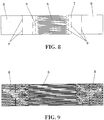
- the heating wires (6) are formed in a heating plate (7) of conductive material and with elongated form, which has a connection surface (8) at each one it its ends, and wherein is connected respectively a first and a second connection terminal. Said conductive wires (6) are straight and are connected between said connection surfaces (8), as shown in figure 8 .
- connection surfaces (8) have transversal cuts (9) in the form of a straight line which define conductive paths of current to produce a uniform distribution of current in the conductive wires (6), as shown in the simulation of figure 9 .
- said conductive paths are defined by at least two parallel groups of aligned cuts (9). These cuts (9) achieve that the distribution of the current is uniform irrespective of the position in which the flexible electrical points (17) are found and with which each terminal of the means of heating is supplied, as observed in figure 2(b) .
- Figure 9 shows the simulations performed in ANSYS which demonstrate that the maximum variation of the current between two heaters of this type does not exceed 0.04 ⁇ A.
- the design of the heating elements incorporates two compensation structures with the same purpose, but to resolve different problems: Compensation of the geometry.
- the electric current always tries to go through the path of least electrical resistance. Due to the symmetrical geometry of the heater, all the resistances, which are located in a parallel configuration, have the same resistance. However, although the area of the external electric contact has been made very large in order so that there is no predominant direction, as it is made with the same material as the resistance, it has a certain electrical resistance. This means that there is a preferred path, the central (if the contact is centred). Due to the required level of uniformity of temperatures due to the application, that small lack of uniformity is not acceptable, for which reason balanced current structures have been designed and simulated between the different branches.
- These structures have the function of equalling the total path in all resistances so that there is not one more favourable than the others.
- These structures are T-shaped.
- the central area of the T has the aim of cutting a short path and deviating the current through the sides. 4 levels have been added, this number depending on the degree of uniformity required. As it goes up a level, the "T" is of greater size (25%), covering a greater surface. Each arm of the T is equivalent to the distance between this and the previous T.
- the opening should be a third of the opening which is seen in the last line of "T" (the closest to the electric contact). The separation between this opening and the closest line of the "T” should be so that the angle opened is 25o.
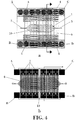
- the PCR device has six heating plates (7) placed in parallel as shown in figure 4(b) , and preferably transversally to the reaction chamber (1).
- Each heating plate (7) has 32 tracks of wires (6) of Pt of 20 ⁇ m width and 5 mm in length, separated 50 ⁇ m from one another, which end in two electric contacts (one on each side of the chip), through which they are supplied at 45 V by an external power source. It has conductive wires (6) under the whole area of the reaction chamber (1) as is observed in figure 4 , so that all zones of the chamber are uniformly heated.
- the PCR device contains a temperature sensor, in particular a resistance sensor (10) of four wires, placed in the centre of the reaction chamber (1) as shown in figure 4 .
- a temperature sensor in particular a resistance sensor (10) of four wires, placed in the centre of the reaction chamber (1) as shown in figure 4 .
- the contacts (A,B,C,D) are those belonging to the temperature sensor.
- This resistance sensor (10), shown in figure 6 is based on the principle that the electrical resistance of the platinum depends on the temperature and varies linearly with it. When the sensor is supplied with a voltage of 4.5 V through contacts (A) and (B) and the current is measured through contacts (C) and (D), it is possible to calculate the resistance and therefore the temperature in the centre of the PCR chamber.
- the heating wires (6) are immersed in one of the walls that form the reaction chamber (1).
- the wires can go on the pyrex or on the SU-8. In a preferred configuration the wires go on the pyrex and coated with a layer of SU-8-5.
- the device For the use of the device it is necessary to fill the chamber with a PCR mixture, and then close the inlet and outlet micro-conduits (2,3) of the chamber (1) by the use of an encapsulation with Silicon seals which close the inlet and outlet orifices.
- the encapsulation is based on two capsules or bases pressed together with screws (11), which leaves the reaction chamber (1) in the middle.
- the lower capsule (12) acts as support of the reaction chamber (1) formed on the substrate (5), whilst the upper capsule (13) acts as support for a PCB (printed circuit board) (14) and contains an o-ring (15) for each inlet/outlet of the chamber (1), as well as two orifices (16) which place in contact the inlet/outlet of micro size of the device with connectors of greater size whereto can be joined a tube or syringe as shown in figure 10 .
- PCB printed circuit board
- the upper capsule (13) places in contact through retractile electrical points (17) in its interior, the contacts of the PCB (14) with the electrodes of the PCR device, so that through electric contacts (21) existing in the PCB (14) it is possible to supply the means of heating by an external power source.
- the (11), the PCR chip is fluidically and electrically capsulated without the need for adhesives, so that it is possible to easily replace and connect the PCR device, it being possible to easily use the same encapsulation for different chips.
- the lower capsule and the upper capsule respectively have an upper opening (18) and a lower opening (19), both the size of the chamber (1) to, on the one hand, place magnets (20) on the surface of the chip and, on the other hand, have visual access to the inside of the chamber (1) when the fluorescence is measured.
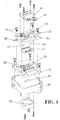
- Figure 1 shows the process to encapsulate the device, fluidically and electronically.
- the upper capsule or base (13) and the lower capsule or base (12) can be seen, made in PMMA, with screws (11) and pins to facilitate the alignment.
- the PCB (14) is also observed with various electronic components to supply the means of heating and the electrical connector in the lower part.
- the device encapsulation is mounted on a support (22) which has a central opening (23), so that a fan (24) is coupled at its lower part to be able to more quickly cool the reaction chamber. It can be observed that both capsules have grooves (25) which favour the passage of air driven by the fan to facilitate the cooling by forced convention.
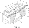
- the upper capsule or base (13) has an inlet conduit (26) and an outlet conduit (27), which connect respectively with said inlet and outlet micro-conduits (2,3) of the reaction chamber (1), through the internal conduits (28,29) as shown in figure 19 .
- the sample is introduced in the reaction chamber (1), for example, by a syringe as represented in figure 10 .
- the encapsulation should permit the placement of the magnets (20) very close to the chip, i.e. to the reaction chamber (1), in addition to not hindering its cooling or the light beam.
- the openings (18) and (19) of the upper and lower capsules make it possible to place the magnets (20) inside them so that they can be later removed.
- a universal concentration system which permits the capture and concentration of biological samples (microbiological, clinical, food, environmental, etc).
- This system can use superparamagnetic particles coated by specific antibodies or superparamagnetic particles that specifically attract nucleic acids.
- On placing the test sample in liquid state with the magnetic particles it achieves a preconcentration of the fraction which contains the specific sequence for the PCR reaction.
- a volume of the sample which can be analysed (1-3 ml), is made to pass through the micro-chamber (1) whist applying a magnetic field thereto.
- the volume of the sample can be between 1-10 ml.
- the sample Once the sample has been introduced in the chamber through the inlet, it is displaced, by the movement of the syringe plunger, throughout the chamber to the outlet where it is eliminated to the outside of the encapsulation maintaining the magnetic field.
- the sample exits the chamber (1) through the micro-conduit (3) which connects with the outlet conduit (27) through the inner conduit (29).
- the gasket seal (15) avoids any leak in the passage of liquid between the micro-conduit (3) and the inner conduit (29).
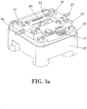
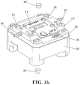
- the magnetic field is applied on placing the two magnets (20) on the reaction chamber (1), one in the upper part and another in the lower part, as shown in figure 3 .
- the encapsulation makes it possible to place the magnets very close to the micro-chamber.
- the upper magnet is in contact with the cover of the micro-chamber, which has an approximate thickness between 70 ⁇ m and 100 ⁇ m, which makes it possible to perform an extremely efficient magnetic capture due to the proximity of the magnet.
- the lower magnet is in contact with the pyrex substrate (5), which has a thickness between 750 ⁇ m and 750 ⁇ m.
- the PCR mixture is then introduced in the same reaction chamber (1), the magnets (20) are removed to then proceed with the amplification reaction.
- the following universal systems can be used which permit the capture and concentration of genetic material: superparamagnetic particles (DYNAL ⁇ ) which specifically trap nucleic acids and superparamagnetic particles coated by covalent bonding, by specific antibodies to a target analyte.
- superparamagnetic particles DYNAL ⁇
- the sample, with this complex is introduced through the inlet of the encapsulation and is made to pass through the reaction chamber (1) where, when necessary, the biomolecules (DNA and RNA) and the PCR reaction is performed and, at the same time, a magnetic field is applied which retains the magnetic particles inside the micro-chamber. In this way, after the passage of the solution, only the magnetic particle-target analyte complex, which includes the specific sequence, which serves as mould for the PCR reaction, is retained in the chamber.
- the PCR mixture is introduced therein.
- the chip, encapsulated and perfectly closed, is placed under an epifluorescent microscope or a CCD chamber of a photomultiplier with the respective optical filters which permit measuring the fluorescence.
- the pre-activation time necessary for the polymerase enzyme is sufficient to provoke the lysis of the target analyte, contained in the chamber in the form of magnetic particle-antibody-analyte complex and leave accessible the nucleic acid (DNA and RNA) for its subsequent detection by amplification.
- the amplification program contains the temperature cycles corresponding to pre-activation of the enzyme and amplification (denaturing, hybridization and extension), in a range between ambient temperature and 95oC.
- amplification product by real-time PCR is observed in the chip, through the transparent coating of SU-8, and it is possible to use specific molecular probes for the product amplified and labelled at end 5' with fluorophore, for example Cy5, at end 3' with BHQ-2.
- Cy5 is a registered trademark of GE Healthcare Bio-Sciences, Little Chalfont, United Kingdom.
- BHQ-2 is registered trademark of Biosearch Technologies, Inc., Novato, CV).
- the fluorescence is measured during the amplification reaction using voltage units. When the sample is positive, an exponential increase in the fluorescence is observed until reaching a maximum. The start of this increase in fluorescence occurs from a certain cycle of amplification, which depends on the initial quantity of nucleic acid. The complete amplification protocol lasts no longer than 30 minutes.
- the PCR reaction chamber (1) remains in contact with the air, for three main reasons: (i) To be able to place the magnets in contact with the chip; (ii) So that the cooling is quicker and (iii) To be able to perform the optical detection.
- the magnets (20) are placed one under the other above the chamber, by hand, so that they fit through the openings (18) and (19) of the capsule for which reason it is very easy to concentrate the sample and extract the nucleic acid and remove them subsequently to be able to amplify the nucleic acid and be able to perform the optical detection.
- the external electronic apparatus for the heating of the means of heating consists of:
- the system of heating works as follows: in first place, the sensor of the chip measures the resistance (and with it the temperature of the chamber) and according to the temperature needed at any time, it is decided whether to supply the heaters or the fan. If the temperature measured is less than needed at that time, the voltage source which supplies the heaters switches on and heats the chamber until reaching the desired temperature. But if, in contrast, the temperature measured by the sensor is greater than that needed at that time, the voltage source which supplies the fan switches on to cool the PCR chamber. All of this is controlled by software connected to the data collection system.
- the data collection apparatus is based on a microscope and contains:
- the viewing of the amplified nucleic acid is possible thanks to the accumulation for each amplification cycle of flurochrome Cy5, which is excited at 640 mm and emits at 670 mm.
- the light emitted by the mercury lamp passes through the excitation filter. This only lets the light of 640 mm pass through, which reaches the sample. In consequence, the flurochrome is excited and emits a red light of 670 mm which is deviated towards the emission filter, thanks to the dichroic mirror. Finally, this emission light reaches the photomultiplier, which is connected to a data collection system.
- the upper capsule or base (13) has an orifice (18) situated above the chamber (1), so that it permits this type of optical detection, since the cover of the micro-chamber is transparent. Furthermore, it is important to highlight that the SU-8, unlike other polymeric materials, has a very low autofluorescence at this wavelength, so that it makes it possible to detect the fluorescence signal of the sample labelled with Cy5.
- the magnets (20) used for the preparation of the sample are Neodymium-lron-Bro (NdFeB) and they have the shape of a disc, as observed in figure 3b , with a diameter of 10 mm and a height of 4 mm.
- the orientation of the magnetization is axial with a (B-H) max of 30 MGO e .
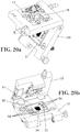
- Figure 20 has represented another preferred embodiment of the invention, wherein the upper base (13) and the lower base (12) of the encapsulation, are joined in hinged or articulated form at one of their sides, forming a portable device of small dimensions.
- the PCR (30) chip which includes the reaction chamber (1), the micro-conduits (2,3) and the means of heating, is embedded in a plastic support (31) which has windows (32,32') respectively on its upper and lower faces, which give access to the chip (30) as shown in figure 21 .
- the plastic support (31) In one of the surfaces of the plastic support (31) are arranged two orifices (33) connected inside the plastic support with the micro-conduits (2,3).
- the plastic support also has orifices (34) on one of its surfaces which give access to electric terminals (38) connected to the means of heating and the temperature sensor of the chip (30).
- the plastic support (31) is formed by several sheets as observed in figure 21 .
- it has an upper sheet (35) and a lower sheet (36), between which is arranged in a sandwich type structure, the chip (30).
- the plastic support closes the encapsulation bases, so that the conduits (26,27) disposed on one of the bases, are connected to the orifices (33) of the plastic support (31). Similarly, electric contacts (39) are placed inside one of the bases to contact with the terminals (38) on closing the encapsulation.
- a fan can be positioned in one of the bases, to drive air with the object of reducing the temperature of the reaction chamber when necessary.
- the PCR devices are manufactured on pyrex substrates.
- polymeric substrates such as, for example, PMMA as is described in patent IS-2,255,463 and without any substrate apart from the SU-8 in patent IS-2,263,400 , so that its manufacturing cost is considerably reduced.
- a pyrex substrate whereon is carried out a photolithography process with the positive photoresin S1818, using the appropriate mask.
- an adherence promoter is first deposited and then the resin at 4000 rpm during 30 seconds, the substrate is subjected to a thermal treatment at 90oC during 20 minutes, it is exposed to UV light with a dose of 300 mJ/cm 2 and it is removed.
- the lower substrate is the same pyrex substrate where the electrodes have previously been manufactured and the upper substrate, which is a Kapton film adhered to a pyrex substrate.
- the seed layer of SU-8-5 is manufactured on this substrate with two objectives: (i) to electrically insulate the electrodes and (ii) to improve adherence between the pyrex substrate and the chambers manufactured in SU-8-50.
- SU-8-5 and the SU-8-50 are chemically similar, the only difference existing between these two commercial products is the viscosity, which depends on the quantity of solvent they carry.
- the viscosity of the SU-8-5 (approximately 290 cSt) is much less than that of the SU-8-50 (approximately 2250 cSt). Therefore, the thickness of the layer of SU-8-5 is much less after being deposited by centrifugation on the pyrex substrate.
- the adherence of this fine layer is better than the adherence of a thicker layer of the same material.
- the substrate is immersed in a PGMEA bath with stirring during 2 minutes and it is rinsed with IPA.
- the photoresin which has not been polymerized is dissolved, the seed layer of SU-8-5 remaining on the pyrex substrate.
- the adherence is improved as the degree of polymerization of the photoresin is increased. Therefore, the substrate is subjected to a last thermal treatment (30 minutes at 170 oC) wherein this degree of polymerization considerably increases.
- the cavities of the PCR chambers can be manufactured with their microchannels in it, by another photolithography process. But this time a thicker layer of SU-8-50 is used, which can vary between 20 and 200 ⁇ m of thickness, according to the height of chamber desired. Although some process parameters may change, the procedure to follow is similar. In first place 2 ml of resin are deposited and the substrate is rotated during a few seconds to produce a uniform layer. Then, the solvent is evaporated with thermal treatment at 90oC. Then the resin polymerizes by exposure to UV light and a thermal treatment at 90oC. Finally, the non-polymerized resin is developed to produce the desired structures. In this case, the degree of polymerization is relatively low so that it can continue polymerizing afterwards during the adherence process, in contact with another layer of SU-8.
- the last layer deposited on the substrate is always 20 ⁇ m in height, since the subsequent adherence process is optimized for these layers of SU-8.
- the photolithography on the kapton is carried out exactly the same as the photolithography of the cavities, but with the suitable mask.
- a layer of SU-8-50 of 100 ⁇ m thickness is manufactured so that the cover of the PCR chamber is sufficiently rigid to support the pressure generated during the thermocycling.
- a layer of 80 ⁇ m is first deposited, its solvent is evaporated at 90oC during 30 minutes.
- a layer of SU-8-50 is again deposited at 20 ⁇ m and its solvent is evaporated at 90oC during 8 minutes.
- the layer is polymerized at 90oC during 4 minutes.
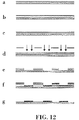
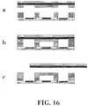
- Figure 16 shows a diagram of this manufacturing process, which is composed of the following operational areas:
- Adherence between the kapton film and the SU-8 is very poor. Due to this, it is possible to release to upper substrate after the adherence process. To do this, the two substrates are introduced adhered in an IPA ultrasound bath during 10 minutes and the pyrex substrate is removed with the aid of a knife.
- the two layers of SU-8 are produced adhered together on the pyrex substrate forming the sealed PCR chambers, with integrated platinum electrodes.
- a pyrex substrate is achieved which contains 16 PCR devices. Therefore, cutting this substrate in the cutter gives rise to 16 devices.
Landscapes
- Chemical & Material Sciences (AREA)
- Health & Medical Sciences (AREA)
- Chemical Kinetics & Catalysis (AREA)
- General Health & Medical Sciences (AREA)
- Clinical Laboratory Science (AREA)
- Dispersion Chemistry (AREA)
- Fluid Mechanics (AREA)
- Analytical Chemistry (AREA)
- Hematology (AREA)
- Physics & Mathematics (AREA)
- Life Sciences & Earth Sciences (AREA)
- Biochemistry (AREA)
- Molecular Biology (AREA)
- Apparatus Associated With Microorganisms And Enzymes (AREA)
- Automatic Analysis And Handling Materials Therefor (AREA)
Claims (8)
- Vorrichtung zum spezifischen Nachweis von genetischem Material durch Echtzeit-Polymerase-Kettenreaktion, die eine Reaktionskammer (1) umfasst, welche für die Durchführung der Polymerase-Kettenreaktion geeignet ist und für den Einlass und Auslass einer zu analysierenden Probe in bzw. aus der Reaktionskammer (1) mit einer Einlassmikroleitung (2) bzw. einer Auslassmikroleitung (3) verbunden ist, dadurch gekennzeichnet, dass sie umfasst:ein Substrat (5), in dem die Reaktionskammer (1) gebildet ist;eine obere Basis (13) und eine untere Basis (12), so dass das Substrat (5) zwischen der oberen und der unteren Basis (13, 12) zurückgehalten wird;Heizeinrichtungen, die eine Vielzahl von leitfähigen Drähten (6) umfassen, die zwischen zwei Terminals verbunden sind, und wobei die Heizeinrichtungen in das Substrat (5) integriert sind und wobei die leitfähigen Drähte unterhalb der Oberfläche der ganzen Reaktionskammer (1) gleichmäßig verteilt sind, um die Reaktionskammer (1) zu heizen, und so konfiguriert sind, dass die Amplifikation des genetischen Materials in der Reaktionskammer (1) erfolgen kann;eine erste Öffnung (18) in der oberen Basis, die visuellen Zugang zu einem oberen Teil der Kammer gewährt, und eine zweite Öffnung (19) in der unteren Basis, die visuellen Zugang zu einem unteren Teil der Reaktionskammer (1) gewährt;ein Paar Magneten (20), wobei die Magneten (20) in Größe und Form so angepasst sind, dass sie lösbar in der ersten bzw. zweiten Öffnung (18, 19) untergebracht sein können;wobei die erste und die zweite Öffnung (18, 19) visuellen Zugang zum Inneren der Reaktionskammer (1) gewähren, um einen Fluoreszenznachweis des genetischen Materials innerhalb der Reaktionskammer (1) zu ermöglichen;einen Temperaturfühler (10), der so angeordnet ist, dass er die Temperatur in der Reaktionskammer (1) misst;elektrische Kontakte, die sich in wenigstens einer der oberen oder der unteren Basis (13, 12) befindet und elektrisch mit der Heizeinrichtung und dem Temperaturfühler verbunden ist.
- Vorrichtung gemäß Anspruch 1, dadurch gekennzeichnet, dass das Substrat (5) in zerlegbarer Weise zwischen der oberen und der unteren Basis (13, 12) zurückgehalten wird.
- Vorrichtung gemäß einem der vorstehenden Ansprüche, dadurch gekennzeichnet, dass der Temperaturfühler (10) in das Substrat (5) integriert ist, wobei die Reaktionskammer (1) entsteht.
- Vorrichtung gemäß einem der vorstehenden Ansprüche, dadurch gekennzeichnet, dass wenigstens eine der Wände, die die Reaktionskammer (1) bilden, transparent ist.
- Vorrichtung gemäß einem der vorstehenden Ansprüche, dadurch gekennzeichnet, dass eine der Basen (13, 12) eine Einlassleitung und eine Auslassleitung aufweist, die mit der Einlass- bzw. Auslassmikroleitung (2, 3) der Reaktionskammer (1) verbunden sind.
- Vorrichtung gemäß einem der vorstehenden Ansprüche, dadurch gekennzeichnet, dass das Substrat (5), in dem die Reaktionskammer (1) gebildet ist, die Einlass- und Auslassmikroleitung (2, 3) und die Heizeinrichtungen zwischen einer oberen und einer unteren Kunststoffplatte (35, 36), die einen abnehmbaren Kunststoffträger (31) bilden, platziert sind und dass der Kunststoffträger (31) ein Fenster (32, 32') aufweist, durch das hindurch die Reaktionskammer (1) zugänglich ist, und wobei der Kunststoffträger (31) zwei Perforationen (34) in einer seiner Flächen, die mit der Einlass- bzw. Auslassmikroleitung (2, 3) der Reaktionskammer (1) verbunden sind, aufweist und wobei der Kunststoffträger (31) elektrische Anschlüsse (38) aufweist, die von einer seiner Flächen her zugänglich sind und die mit den in das Substrat (5) eingetauchten Heizeinrichtungen verbunden sind.
- Vorrichtung gemäß einem der vorstehenden Ansprüche, dadurch gekennzeichnet, dass wenigstens ein Teil der leitfähigen Drähte (6) im Wesentlichen parallel zueinander verlaufen, wobei die Heizeinrichtungen wenigstens eine längliche Leitungsplatte umfassen, die an jedem ihrer Enden Anschlussflächen aufweist, und in denen sich ein erster bzw. ein zweiter Verbindungsanschluss befinden, und dass die leitfähigen Drähte gerade sind und zwischen den Anschlussflächen verbunden sind, und wobei jeder Verbindungsanschluss über leitfähige Bahnen, die in den Anschlussflächen definiert sind, mit den leitfähigen Drähten verbunden ist, wobei eine gleichmäßige Stromverteilung in den leitfähigen Drähten entsteht und wobei die Anschlussflächen Querschnitte in Form einer Geraden aufweisen, die die leitfähigen Bahnen definieren, und wobei die Vorrichtung wenigstens zwei parallele Gruppen von aneinander ausgerichteten Schnitten aufweist.
- Vorrichtung gemäß einem der vorstehenden Ansprüche, dadurch gekennzeichnet, dass eine der Basen elektrische Anschlüsse aufweist, die mit den Anschlussflächen der Heizeinrichtungen in Kontakt stehen.
Applications Claiming Priority (1)
| Application Number | Priority Date | Filing Date | Title |
|---|---|---|---|
| PCT/ES2007/000163 WO2008116941A1 (es) | 2007-03-26 | 2007-03-26 | Método y dispositivo para la detección de material genético mediante reacción en cadena de polimerasa |
Publications (3)
| Publication Number | Publication Date |
|---|---|
| EP2149610A1 EP2149610A1 (de) | 2010-02-03 |
| EP2149610A4 EP2149610A4 (de) | 2014-08-27 |
| EP2149610B1 true EP2149610B1 (de) | 2018-05-16 |
Family
ID=39788063
Family Applications (1)
| Application Number | Title | Priority Date | Filing Date |
|---|---|---|---|
| EP07730404.6A Not-in-force EP2149610B1 (de) | 2007-03-26 | 2007-03-26 | Vorrichtung zum nachweis genetischen materials mittels polymerasekettenreaktion |
Country Status (4)
| Country | Link |
|---|---|
| US (1) | US20100112579A1 (de) |
| EP (1) | EP2149610B1 (de) |
| BR (1) | BRPI0721509A2 (de) |
| WO (1) | WO2008116941A1 (de) |
Cited By (1)
| Publication number | Priority date | Publication date | Assignee | Title |
|---|---|---|---|---|
| WO2026059461A1 (en) * | 2024-09-12 | 2026-03-19 | Terrabio Sp. Z O. O. | Portable analyzer |
Families Citing this family (9)
| Publication number | Priority date | Publication date | Assignee | Title |
|---|---|---|---|---|
| DE102009055800B4 (de) * | 2009-11-18 | 2013-01-03 | Fraunhofer-Gesellschaft zur Förderung der angewandten Forschung e.V. | System und ein Verfahren zur Detektion von in flüssigen Proben enthaltenen Analytmolekülen |
| US11648561B2 (en) | 2012-02-13 | 2023-05-16 | Neumodx Molecular, Inc. | System and method for processing and detecting nucleic acids |
| US9738887B2 (en) | 2012-02-13 | 2017-08-22 | Neumodx Molecular, Inc. | Microfluidic cartridge for processing and detecting nucleic acids |
| WO2014066376A1 (en) * | 2012-10-25 | 2014-05-01 | Neumodx Molecular, Inc. | Method and materials for isolation of nucleic acid materials |
| WO2016097429A1 (es) * | 2014-12-18 | 2016-06-23 | Ikerlan, S. Coop. | Dispositivo desechable adecuado para la realización simultánea de una pluralidad de experimentos biológicos en muestras fluídicas |
| TWI603447B (zh) * | 2014-12-30 | 2017-10-21 | 精材科技股份有限公司 | 晶片封裝體及其製造方法 |
| US12576404B2 (en) * | 2018-04-30 | 2026-03-17 | The Johns Hopkins University | Disposable reagent scaffold for biochemical process integration |
| CN111849760B (zh) * | 2020-08-31 | 2025-10-28 | 苏州思纳福医疗科技有限公司 | 一种pcr反应装置 |
| CN114210377B (zh) * | 2021-12-21 | 2023-01-06 | 哈尔滨工业大学 | 一种基于电场调控的便携式多功能可视化微流体设备 |
Family Cites Families (19)
| Publication number | Priority date | Publication date | Assignee | Title |
|---|---|---|---|---|
| US881541A (en) * | 1907-07-18 | 1908-03-10 | Richard W Buckley Jr | Anchor. |
| NL9002696A (nl) * | 1990-11-15 | 1992-06-01 | U Gene Research Bv | Werkwijze en kit voor het aantonen van microoerganismen. |
| US5795470A (en) | 1991-03-25 | 1998-08-18 | Immunivest Corporation | Magnetic separation apparatus |
| GB9107124D0 (en) * | 1991-04-05 | 1991-05-22 | Dynal As | Chemical process |
| US5994056A (en) | 1991-05-02 | 1999-11-30 | Roche Molecular Systems, Inc. | Homogeneous methods for nucleic acid amplification and detection |
| US6953676B1 (en) * | 1992-05-01 | 2005-10-11 | Trustees Of The University Of Pennsylvania | Mesoscale polynucleotide amplification device and method |
| US5639423A (en) * | 1992-08-31 | 1997-06-17 | The Regents Of The University Of Calfornia | Microfabricated reactor |
| US5849208A (en) * | 1995-09-07 | 1998-12-15 | Microfab Technoologies, Inc. | Making apparatus for conducting biochemical analyses |
| US5863502A (en) * | 1996-01-24 | 1999-01-26 | Sarnoff Corporation | Parallel reaction cassette and associated devices |
| US6572830B1 (en) * | 1998-10-09 | 2003-06-03 | Motorola, Inc. | Integrated multilayered microfludic devices and methods for making the same |
| US6159378A (en) | 1999-02-23 | 2000-12-12 | Battelle Memorial Institute | Apparatus and method for handling magnetic particles in a fluid |
| DE60022025T2 (de) | 1999-05-28 | 2006-06-29 | Cepheid, Sunnyvale | Anlage zum brechen von zellen |
| FR2826592B1 (fr) * | 2001-06-27 | 2003-08-15 | Bio Merieux | Procede, dispositif, et equipement de separation par voie humide de micro particules magnetiques |
| EP1331035A1 (de) | 2002-01-23 | 2003-07-30 | F. Hoffmann-La Roche AG | Apparat zum Zurückhalten von Magnetteilchen in einer von einer Flüssigkeit durchströmte Zelle |
| WO2005023427A1 (en) | 2003-09-05 | 2005-03-17 | Stokes Bio Limited | A microfluidic analysis system |
| KR100580639B1 (ko) * | 2003-12-30 | 2006-05-16 | 삼성전자주식회사 | 미세유체 검출을 위한 형광검출기 |
| DE102004021780B4 (de) * | 2004-04-30 | 2008-10-02 | Siemens Ag | Verfahren und Anordnung zur DNA-Isolierung mit Trockenreagenzien |
| JP4183256B2 (ja) * | 2004-08-04 | 2008-11-19 | キヤノン株式会社 | 核酸増幅反応産物の鎖分離方法、核酸増幅反応産物の検出方法 |
| EP1650297B1 (de) * | 2004-10-19 | 2011-04-13 | Samsung Electronics Co., Ltd. | Verfahren und Apparatur zur schnellen Zerstörung von Zellen und Viren durch die Verwendung von mikro magnet Kügelchen und Laser |
-
2007
- 2007-03-26 EP EP07730404.6A patent/EP2149610B1/de not_active Not-in-force
- 2007-03-26 US US12/593,283 patent/US20100112579A1/en not_active Abandoned
- 2007-03-26 BR BRPI0721509-6A patent/BRPI0721509A2/pt not_active IP Right Cessation
- 2007-03-26 WO PCT/ES2007/000163 patent/WO2008116941A1/es not_active Ceased
Non-Patent Citations (1)
| Title |
|---|
| None * |
Cited By (1)
| Publication number | Priority date | Publication date | Assignee | Title |
|---|---|---|---|---|
| WO2026059461A1 (en) * | 2024-09-12 | 2026-03-19 | Terrabio Sp. Z O. O. | Portable analyzer |
Also Published As
| Publication number | Publication date |
|---|---|
| BRPI0721509A2 (pt) | 2013-01-15 |
| EP2149610A1 (de) | 2010-02-03 |
| EP2149610A4 (de) | 2014-08-27 |
| US20100112579A1 (en) | 2010-05-06 |
| WO2008116941A1 (es) | 2008-10-02 |
Similar Documents
| Publication | Publication Date | Title |
|---|---|---|
| EP2149610B1 (de) | Vorrichtung zum nachweis genetischen materials mittels polymerasekettenreaktion | |
| CN102083533B (zh) | 微流控芯片装置及其使用 | |
| US6878540B2 (en) | Device for lysing cells, spores, or microorganisms | |
| US6893879B2 (en) | Method for separating analyte from a sample | |
| US9181571B2 (en) | Reusable PCR amplification system and method | |
| US8968585B2 (en) | Methods of fabrication of cartridges for biological analysis | |
| US9416343B2 (en) | Instruments for biological sample-to-answer devices | |
| US9518291B2 (en) | Devices and methods for biological sample-to-answer and analysis | |
| US20130220931A1 (en) | Composition, apparatus, and method for separating an analyte from a sample | |
| JP2006504974A (ja) | 薄膜層を用いて流体を誘導するマイクロ流体システム | |
| CN1157639A (zh) | 中型多核苷酸扩增装置 | |
| US9090890B2 (en) | Devices and methods for biological sample preparation | |
| US10308977B2 (en) | Device and method for processing a biological sample and analysis system for analyzing a biological specimen | |
| US20140057278A1 (en) | Pen-shaped device for biological sample preparation and analysis | |
| CN115427149B (zh) | 以微移液器形式进行的多重聚合酶链反应 | |
| WO2014071259A1 (en) | Methods of fabrication of cartridges for biological analysis | |
| WO2014071258A1 (en) | Devices and methods for biological sample-to-answer and analysis | |
| WO2014071260A1 (en) | Pen-shaped device for biological sample preparation and analysis | |
| AU2003200701B2 (en) | Integrated fluid manipulation cartridge | |
| Lee et al. | Submicroliter-volume bulk-micromachined Si-PMMA thermal cycler with a multi-stacked dielectric membrane | |
| Banerjee | A PROTOTYPE ON-CHIP MICRO-HEATER FOR DISPOSABLE MICRO-PCR MODULE | |
| AU8364801A (en) | Integrated fluid manipulation cartridge |
Legal Events
| Date | Code | Title | Description |
|---|---|---|---|
| PUAI | Public reference made under article 153(3) epc to a published international application that has entered the european phase |
Free format text: ORIGINAL CODE: 0009012 |
|
| 17P | Request for examination filed |
Effective date: 20091026 |
|
| AK | Designated contracting states |
Kind code of ref document: A1 Designated state(s): AT BE BG CH CY CZ DE DK EE ES FI FR GB GR HU IE IS IT LI LT LU LV MC MT NL PL PT RO SE SI SK TR |
|
| AX | Request for extension of the european patent |
Extension state: AL BA HR MK RS |
|
| DAX | Request for extension of the european patent (deleted) | ||
| A4 | Supplementary search report drawn up and despatched |
Effective date: 20140728 |
|
| RIC1 | Information provided on ipc code assigned before grant |
Ipc: B01J 19/00 20060101ALI20140722BHEP Ipc: G01N 33/50 20060101ALI20140722BHEP Ipc: B01L 3/00 20060101ALI20140722BHEP Ipc: C12Q 1/68 20060101AFI20140722BHEP Ipc: B01L 7/00 20060101ALI20140722BHEP |
|
| GRAP | Despatch of communication of intention to grant a patent |
Free format text: ORIGINAL CODE: EPIDOSNIGR1 |
|
| STAA | Information on the status of an ep patent application or granted ep patent |
Free format text: STATUS: GRANT OF PATENT IS INTENDED |
|
| INTG | Intention to grant announced |
Effective date: 20180103 |
|
| RIN1 | Information on inventor provided before grant (corrected) |
Inventor name: VERDOY BERASTEGUI, DOLORES Inventor name: OLABARRIA DE PABLO, GARBINE Inventor name: RUANO LOPEZ, JESUS, MIGUEL Inventor name: BERGANZO RUIZ, JAVIER |
|
| GRAS | Grant fee paid |
Free format text: ORIGINAL CODE: EPIDOSNIGR3 |
|
| GRAA | (expected) grant |
Free format text: ORIGINAL CODE: 0009210 |
|
| STAA | Information on the status of an ep patent application or granted ep patent |
Free format text: STATUS: THE PATENT HAS BEEN GRANTED |
|
| AK | Designated contracting states |
Kind code of ref document: B1 Designated state(s): AT BE BG CH CY CZ DE DK EE ES FI FR GB GR HU IE IS IT LI LT LU LV MC MT NL PL PT RO SE SI SK TR |
|
| REG | Reference to a national code |
Ref country code: GB Ref legal event code: FG4D |
|
| REG | Reference to a national code |
Ref country code: CH Ref legal event code: EP |
|
| REG | Reference to a national code |
Ref country code: IE Ref legal event code: FG4D |
|
| REG | Reference to a national code |
Ref country code: DE Ref legal event code: R096 Ref document number: 602007054846 Country of ref document: DE |
|
| REG | Reference to a national code |
Ref country code: AT Ref legal event code: REF Ref document number: 999609 Country of ref document: AT Kind code of ref document: T Effective date: 20180615 |
|
| REG | Reference to a national code |
Ref country code: NL Ref legal event code: MP Effective date: 20180516 |
|
| REG | Reference to a national code |
Ref country code: LT Ref legal event code: MG4D |
|
| PG25 | Lapsed in a contracting state [announced via postgrant information from national office to epo] |
Ref country code: ES Free format text: LAPSE BECAUSE OF FAILURE TO SUBMIT A TRANSLATION OF THE DESCRIPTION OR TO PAY THE FEE WITHIN THE PRESCRIBED TIME-LIMIT Effective date: 20180516 Ref country code: LT Free format text: LAPSE BECAUSE OF FAILURE TO SUBMIT A TRANSLATION OF THE DESCRIPTION OR TO PAY THE FEE WITHIN THE PRESCRIBED TIME-LIMIT Effective date: 20180516 Ref country code: BG Free format text: LAPSE BECAUSE OF FAILURE TO SUBMIT A TRANSLATION OF THE DESCRIPTION OR TO PAY THE FEE WITHIN THE PRESCRIBED TIME-LIMIT Effective date: 20180816 Ref country code: SE Free format text: LAPSE BECAUSE OF FAILURE TO SUBMIT A TRANSLATION OF THE DESCRIPTION OR TO PAY THE FEE WITHIN THE PRESCRIBED TIME-LIMIT Effective date: 20180516 Ref country code: FI Free format text: LAPSE BECAUSE OF FAILURE TO SUBMIT A TRANSLATION OF THE DESCRIPTION OR TO PAY THE FEE WITHIN THE PRESCRIBED TIME-LIMIT Effective date: 20180516 |
|
| PG25 | Lapsed in a contracting state [announced via postgrant information from national office to epo] |
Ref country code: GR Free format text: LAPSE BECAUSE OF FAILURE TO SUBMIT A TRANSLATION OF THE DESCRIPTION OR TO PAY THE FEE WITHIN THE PRESCRIBED TIME-LIMIT Effective date: 20180817 Ref country code: LV Free format text: LAPSE BECAUSE OF FAILURE TO SUBMIT A TRANSLATION OF THE DESCRIPTION OR TO PAY THE FEE WITHIN THE PRESCRIBED TIME-LIMIT Effective date: 20180516 Ref country code: NL Free format text: LAPSE BECAUSE OF FAILURE TO SUBMIT A TRANSLATION OF THE DESCRIPTION OR TO PAY THE FEE WITHIN THE PRESCRIBED TIME-LIMIT Effective date: 20180516 |
|
| REG | Reference to a national code |
Ref country code: AT Ref legal event code: MK05 Ref document number: 999609 Country of ref document: AT Kind code of ref document: T Effective date: 20180516 |
|
| PG25 | Lapsed in a contracting state [announced via postgrant information from national office to epo] |
Ref country code: SK Free format text: LAPSE BECAUSE OF FAILURE TO SUBMIT A TRANSLATION OF THE DESCRIPTION OR TO PAY THE FEE WITHIN THE PRESCRIBED TIME-LIMIT Effective date: 20180516 Ref country code: PL Free format text: LAPSE BECAUSE OF FAILURE TO SUBMIT A TRANSLATION OF THE DESCRIPTION OR TO PAY THE FEE WITHIN THE PRESCRIBED TIME-LIMIT Effective date: 20180516 Ref country code: DK Free format text: LAPSE BECAUSE OF FAILURE TO SUBMIT A TRANSLATION OF THE DESCRIPTION OR TO PAY THE FEE WITHIN THE PRESCRIBED TIME-LIMIT Effective date: 20180516 Ref country code: EE Free format text: LAPSE BECAUSE OF FAILURE TO SUBMIT A TRANSLATION OF THE DESCRIPTION OR TO PAY THE FEE WITHIN THE PRESCRIBED TIME-LIMIT Effective date: 20180516 Ref country code: CZ Free format text: LAPSE BECAUSE OF FAILURE TO SUBMIT A TRANSLATION OF THE DESCRIPTION OR TO PAY THE FEE WITHIN THE PRESCRIBED TIME-LIMIT Effective date: 20180516 Ref country code: AT Free format text: LAPSE BECAUSE OF FAILURE TO SUBMIT A TRANSLATION OF THE DESCRIPTION OR TO PAY THE FEE WITHIN THE PRESCRIBED TIME-LIMIT Effective date: 20180516 Ref country code: RO Free format text: LAPSE BECAUSE OF FAILURE TO SUBMIT A TRANSLATION OF THE DESCRIPTION OR TO PAY THE FEE WITHIN THE PRESCRIBED TIME-LIMIT Effective date: 20180516 |
|
| REG | Reference to a national code |
Ref country code: DE Ref legal event code: R097 Ref document number: 602007054846 Country of ref document: DE |
|
| PG25 | Lapsed in a contracting state [announced via postgrant information from national office to epo] |
Ref country code: IT Free format text: LAPSE BECAUSE OF FAILURE TO SUBMIT A TRANSLATION OF THE DESCRIPTION OR TO PAY THE FEE WITHIN THE PRESCRIBED TIME-LIMIT Effective date: 20180516 |
|
| PLBE | No opposition filed within time limit |
Free format text: ORIGINAL CODE: 0009261 |
|
| STAA | Information on the status of an ep patent application or granted ep patent |
Free format text: STATUS: NO OPPOSITION FILED WITHIN TIME LIMIT |
|
| 26N | No opposition filed |
Effective date: 20190219 |
|
| PG25 | Lapsed in a contracting state [announced via postgrant information from national office to epo] |
Ref country code: SI Free format text: LAPSE BECAUSE OF FAILURE TO SUBMIT A TRANSLATION OF THE DESCRIPTION OR TO PAY THE FEE WITHIN THE PRESCRIBED TIME-LIMIT Effective date: 20180516 |
|
| REG | Reference to a national code |
Ref country code: DE Ref legal event code: R119 Ref document number: 602007054846 Country of ref document: DE |
|
| PG25 | Lapsed in a contracting state [announced via postgrant information from national office to epo] |
Ref country code: MC Free format text: LAPSE BECAUSE OF FAILURE TO SUBMIT A TRANSLATION OF THE DESCRIPTION OR TO PAY THE FEE WITHIN THE PRESCRIBED TIME-LIMIT Effective date: 20180516 |
|
| REG | Reference to a national code |
Ref country code: CH Ref legal event code: PL |
|
| GBPC | Gb: european patent ceased through non-payment of renewal fee |
Effective date: 20190326 |
|
| PG25 | Lapsed in a contracting state [announced via postgrant information from national office to epo] |
Ref country code: LU Free format text: LAPSE BECAUSE OF NON-PAYMENT OF DUE FEES Effective date: 20190326 |
|
| REG | Reference to a national code |
Ref country code: BE Ref legal event code: MM Effective date: 20190331 |
|
| PG25 | Lapsed in a contracting state [announced via postgrant information from national office to epo] |
Ref country code: LI Free format text: LAPSE BECAUSE OF NON-PAYMENT OF DUE FEES Effective date: 20190331 Ref country code: GB Free format text: LAPSE BECAUSE OF NON-PAYMENT OF DUE FEES Effective date: 20190326 Ref country code: DE Free format text: LAPSE BECAUSE OF NON-PAYMENT OF DUE FEES Effective date: 20191001 Ref country code: CH Free format text: LAPSE BECAUSE OF NON-PAYMENT OF DUE FEES Effective date: 20190331 Ref country code: IE Free format text: LAPSE BECAUSE OF NON-PAYMENT OF DUE FEES Effective date: 20190326 |
|
| PG25 | Lapsed in a contracting state [announced via postgrant information from national office to epo] |
Ref country code: BE Free format text: LAPSE BECAUSE OF NON-PAYMENT OF DUE FEES Effective date: 20190331 Ref country code: FR Free format text: LAPSE BECAUSE OF NON-PAYMENT OF DUE FEES Effective date: 20190331 |
|
| PG25 | Lapsed in a contracting state [announced via postgrant information from national office to epo] |
Ref country code: TR Free format text: LAPSE BECAUSE OF FAILURE TO SUBMIT A TRANSLATION OF THE DESCRIPTION OR TO PAY THE FEE WITHIN THE PRESCRIBED TIME-LIMIT Effective date: 20180516 |
|
| PG25 | Lapsed in a contracting state [announced via postgrant information from national office to epo] |
Ref country code: MT Free format text: LAPSE BECAUSE OF NON-PAYMENT OF DUE FEES Effective date: 20190326 Ref country code: PT Free format text: LAPSE BECAUSE OF FAILURE TO SUBMIT A TRANSLATION OF THE DESCRIPTION OR TO PAY THE FEE WITHIN THE PRESCRIBED TIME-LIMIT Effective date: 20180917 |
|
| PG25 | Lapsed in a contracting state [announced via postgrant information from national office to epo] |
Ref country code: CY Free format text: LAPSE BECAUSE OF FAILURE TO SUBMIT A TRANSLATION OF THE DESCRIPTION OR TO PAY THE FEE WITHIN THE PRESCRIBED TIME-LIMIT Effective date: 20180516 |
|
| PG25 | Lapsed in a contracting state [announced via postgrant information from national office to epo] |
Ref country code: IS Free format text: LAPSE BECAUSE OF FAILURE TO SUBMIT A TRANSLATION OF THE DESCRIPTION OR TO PAY THE FEE WITHIN THE PRESCRIBED TIME-LIMIT Effective date: 20180916 |
|
| PG25 | Lapsed in a contracting state [announced via postgrant information from national office to epo] |
Ref country code: HU Free format text: LAPSE BECAUSE OF FAILURE TO SUBMIT A TRANSLATION OF THE DESCRIPTION OR TO PAY THE FEE WITHIN THE PRESCRIBED TIME-LIMIT; INVALID AB INITIO Effective date: 20070326 |