EP2149690A2 - Turbinenrotor - Google Patents
Turbinenrotor Download PDFInfo
- Publication number
- EP2149690A2 EP2149690A2 EP09166749A EP09166749A EP2149690A2 EP 2149690 A2 EP2149690 A2 EP 2149690A2 EP 09166749 A EP09166749 A EP 09166749A EP 09166749 A EP09166749 A EP 09166749A EP 2149690 A2 EP2149690 A2 EP 2149690A2
- Authority
- EP
- European Patent Office
- Prior art keywords
- rotor
- turbine rotor
- weld
- welding
- contact face
- Prior art date
- Legal status (The legal status is an assumption and is not a legal conclusion. Google has not performed a legal analysis and makes no representation as to the accuracy of the status listed.)
- Withdrawn
Links
Images






Classifications
-
- F—MECHANICAL ENGINEERING; LIGHTING; HEATING; WEAPONS; BLASTING
- F01—MACHINES OR ENGINES IN GENERAL; ENGINE PLANTS IN GENERAL; STEAM ENGINES
- F01D—NON-POSITIVE DISPLACEMENT MACHINES OR ENGINES, e.g. STEAM TURBINES
- F01D5/00—Blades; Blade-carrying members; Heating, heat-insulating, cooling or antivibration means on the blades or the members
- F01D5/02—Blade-carrying members, e.g. rotors
- F01D5/06—Rotors for more than one axial stage, e.g. of drum or multiple disc type; Details thereof, e.g. shafts, shaft connections
- F01D5/063—Welded rotors
-
- B—PERFORMING OPERATIONS; TRANSPORTING
- B23—MACHINE TOOLS; METAL-WORKING NOT OTHERWISE PROVIDED FOR
- B23K—SOLDERING OR UNSOLDERING; WELDING; CLADDING OR PLATING BY SOLDERING OR WELDING; CUTTING BY APPLYING HEAT LOCALLY, e.g. FLAME CUTTING; WORKING BY LASER BEAM
- B23K31/00—Processes relevant to this subclass, specially adapted for particular articles or purposes, but not covered by any single one of main groups B23K1/00 - B23K28/00
- B23K31/02—Processes relevant to this subclass, specially adapted for particular articles or purposes, but not covered by any single one of main groups B23K1/00 - B23K28/00 relating to soldering or welding
-
- B—PERFORMING OPERATIONS; TRANSPORTING
- B23—MACHINE TOOLS; METAL-WORKING NOT OTHERWISE PROVIDED FOR
- B23K—SOLDERING OR UNSOLDERING; WELDING; CLADDING OR PLATING BY SOLDERING OR WELDING; CUTTING BY APPLYING HEAT LOCALLY, e.g. FLAME CUTTING; WORKING BY LASER BEAM
- B23K33/00—Specially-profiled edge portions of workpieces for making soldering or welding connections; Filling the seams formed thereby
- B23K33/004—Filling of continuous seams
-
- F—MECHANICAL ENGINEERING; LIGHTING; HEATING; WEAPONS; BLASTING
- F05—INDEXING SCHEMES RELATING TO ENGINES OR PUMPS IN VARIOUS SUBCLASSES OF CLASSES F01-F04
- F05D—INDEXING SCHEME FOR ASPECTS RELATING TO NON-POSITIVE-DISPLACEMENT MACHINES OR ENGINES, GAS-TURBINES OR JET-PROPULSION PLANTS
- F05D2230/00—Manufacture
- F05D2230/20—Manufacture essentially without removing material
- F05D2230/23—Manufacture essentially without removing material by permanently joining parts together
- F05D2230/232—Manufacture essentially without removing material by permanently joining parts together by welding
Definitions
- the present invention relates to turbine rotors.
- the steam turbine rotor is divided into a plurality of stages, each of which is made of an optimal rotor material. The respective stages are connected together by bolt fastening, welding, or the like, to form one rotor.
- a weld type turbine rotor constructed by welding, has a structure with a cavity sealed at the center of the rotor in assembling rotors so as to reduce stress at start-up.
- the turbine rotor formed by welding allows weld metal to penetrate up to a rotor center hole, thereby to form a penetration bead. Since the inside of the rotor center hole is air atmosphere which cannot be substituted by inert atmosphere, back shield for preventing oxidation cannot be applied.
- welding is performed by introducing a welding torch from an outer peripheral side, the weld metal reacts with air in the center hole, so that the penetration beads are excessively oxidized.
- the shape of the penetration beads excessively oxidized becomes irregular, which may largely differ from that indicated by a design drawing, causing flaws in some cases.
- the turbine rotor does not become a desired one from the viewpoint of the reliability of strength.
- 2000-186509 have proposed that an inspection hole penetrating from the outer periphery of the rotor up to the center hole is provided for inspecting the formed penetration beads, and that a radiographic test (RT) or a visual test (VT) is performed by inserting a radiation source or a camera into the center hole.
- RT radiographic test
- VT visual test
- a through hole for gas charging is provided at the center hole and a back shield is introduced in the through hole.
- a rotor provided with the through hole as described above may receive concentrated stress during the rotation, which is undesirable from the viewpoint of the strength maintenance and the reliability of the rotor.
- An object of the present invention is to provide a welded rotor which is welded without forming the penetration beads. As a result, this eliminates the necessity of inspection of the shape of penetration beads of the welded rotor, improving the reliability of strength of a weld.
- the present invention relates to a steam turbine rotor including a rotor for low pressure and a rotor for high pressure which are integrated by connecting at least parts of the rotors to each other via a weld including weld metal.
- the turbine rotor of the present invention which is to solve the above-mentioned problems, includes the rotor for low pressure and the rotor for high pressure which are in contact with each other via at least two contact faces in a radial direction and/or an axial direction of the turbine rotor in integrating the rotors by welding the respective ends of the rotors.
- the at least two contact faces in a radial direction and/or an axial direction of the turbine rotor comprise at least one contact face in a radial direction and at least one contact face in an axial direction. At least a part of the weld is desirably located on a contact face in the axial direction.
- at least one of the contact faces in the radial direction is located on a lower pressure side with respect to a center line of a welding groove.
- the length of at least one of the contact faces in the radial direction is preferably in a range of 0.5 to 2.0 mm.
- At least one of the contact faces in the axial direction desirably has an end located on a lower pressure side with respect to the center of the welding groove.
- At least one of the contact faces in the axial direction desirably has an end located on a higher pressure side with respect to at least one of the contact faces in the radial direction.
- the turbine rotor preferably has a center hole formed at a center portion of the turbine rotor.
- a steam temperature of 538 to 600°C is 1% Cr-Mo-V steel or 12% Cr steel (see Japanese Patent Publication No. 1833108 or ASTM A470 Class 8).
- Material used for a high and low pressure integrated rotor, which includes rotor components from the high pressure to the low pressure integrally formed of the same material at a steam temperature of 538 to 566 °C, is 2% Ni-2% Cr-Mo-V steel (see Japanese Patent Publication No. 3106121 ).
- a turbine rotor of the present invention is formed by connecting a plurality of members together into which a rotor material is divided.
- Properties required for rotor materials of the large-sized steam turbine rotor are appropriate high-temperature creep rupture strength at high pressure (high temperature), and appropriate tensile strength and toughness at low pressure (low temperature).
- Each stage of the turbine rotor requires different properties. Further, it is difficult for only one material to satisfy both properties for high and low pressures required for the rotor material of the large-sized steam turbine rotor.
- a turbine rotor including one or more rotor stages connected together by welding is disclosed in Mitsubishi Heavy Industries Technical Review, Vol. 37, No. 3 (2000-5 ).
- the turbine rotor of the present invention has a center hole in the rotor member.
- the turbine rotor formed by welding one or more rotor stages allows weld metal to penetrate up to a rotor center hole to forms penetration bead. Since the rotor center hole is sealed in assembly of the rotor, the inside of the rotor center hole remains under air atmosphere, not substituted by inert atmosphere.
- welding is performed in this state by introducing a weld torch from an outer peripheral side, the weld metal reacts with air in the center hole, so that the penetration beads are excessively oxidized.
- the shape of the penetration beads excessively oxidized becomes irregular, which may largely differ from that indicated by a design drawing.
- a hole is provided in a welding groove for charging inert gas into the center hole of the rotor (see Fuji Electric Journal, Vol. 77, No. 2 (2004 )).
- the soundness of shape that is, the conformance to the designed shape, should be examined after the welding step.
- Normal inspection methods include a penetrant test (PT) for the surface of a weld, and an ultrasonic test (UT) for the inside of the weld.
- Aradiographictest (RT) and a visual test (VT) can inspect the shape of the penetration bead. These tests, however, need to introduce a radiation source or a camera into the center hole. It is also proposed that an inspection hole is provided in the rotor to penetrate from the outer periphery up to the center hole. However, the provision of a through hole in the rotor is undesirable from the viewpoint of the reliability of strength. It is also undesirable, from the viewpoint of the reliability of strength, not to inspect the shape of the penetration beads formed at the center hole of the rotor.
- the inventors have studied about a method for securing the reliability of strength of a weld without forming any penetration bead, whose shape needs to be inspected. For example, when butted portions in mating shape are welded as disclosed in Japanese Examined Patent Application Publication No. Hei 06-78721 , the amount of heat input in welding is adjusted so that a penetration depth does not penetrate the butted portion to avoid formation of the penetration beads. A preliminary test, performing welding while adjusting the amount of heat input, showed a result that weld metal was spouted during the welding and sound weld could not be formed.
- Japanese Unexamined Patent Publication No. 2005-344527 discloses that the butted portions obtained after welding have an oblique or zigzag shapes.
- Japanese Unexamined Patent Publication No. 2001-123801 discloses that the butted portions obtained after welding keep the mating shapes provided before welding.
- any of the shapes is designed for the purpose of positioning of the rotor in assembly, that is, reducing an eccentricity of the rotor in rotation, and has only a small effect of preventing the weld metal from spouting in the root pass welding.
- the butted portions with such shapes cannot always prevent the spouting of the weld metal in the root pass wending.
- the inventors have studied about means for enhancing the reliability of strength of the turbine rotor, which is constructed by coupling the butt portions of rotors via the weld without forming any penetration bead in the turbine rotor.
- a rotor for low pressure and a rotors for high pressure are in contact with each other via at least two faces in a radial direction and in an axial direction, respectively, around a center hole part. At least parts of the contact faces are welded and integrated together to form a turbine rotor.
- the rotor for high pressure is provided with stepped portions at a contact end face with the rotor for low pressure.
- the stepped portions are, from the outside, a parallel surface, a vertical surface, and another parallel surface to the radial direction of the rotor.
- the rotor for low pressure is also provided with stepped portions corresponding to engage with those of the rotor for high pressure.
- at least two surfaces parallel to the radial direction are provided on the contact faces, and the contact faces located in the outermost position are welded. The welding may be performed so as to cover the entire contact faces on the outermost side, or so as not to cover the entire contact faces.
- the contact faces parallel to the radial direction of the rotor are discontinuous, whereby no penetration bead is formed. The spouting of air in the center hole is also prevented.
- the inner part of the surfaces parallel, to the radial direction is preferably located closer to the rotor for low pressure than the outer one (that is, the surface parallel to the axial direction of the rotor preferably extends toward the rotor for low pressure than the weld).
- the surface parallel to the radial direction of the rotor is preferably parallel to the radial direction of the rotor to the greatest extent practicable from the viewpoint of design.
- the surface parallel to the axial direction of the rotor may not be strictly parallel to the axis of the rotor.
- Fig. 1 is a sectional view of the turbine rotor for high and low pressure steams according to the present invention.
- the turbine rotor for high and low pressure steam shown in Fig. 1 is divided into two components, that is, a rotor 62 for high pressure and a rotor 61 for low pressure, which are connected to each other by a weld 6 (weld metal 66) to construct the turbine rotor.
- a joint connected by the weld 6 has a hollow portion 64, which decreases the weight of the turbine rotor.
- the rotor 62 for high pressure includes 1% Cr-Mo-V steel.
- the rotor 61 for low pressure includes 3 to 4% Ni-Cr-Mo-V steel.
- Table 1 shows chemical compositions (weight percent) of weld wires and materials constituting the rotor of a typical turbine rotor, the rest of the compositions being Fe.
- the material of the rotor 62 for high pressure includes 1.13 % Cr and the material of the rotor 61 for low pressure includes 1.83 % Cr.
- the weld wire should include an amount of Cr between the amounts of Cr of both rotors.
- the weld wire includes (1) 1.22 % Cr or (2) 2.22 % Cr, which is more than the amounts of both rotors, so as not to reduce the strength of the wire even under the heat treatment at a temperature equal to or higher than a last tempering temperature of both rotors.
- Fig. 2 is a partial sectional view of a weld joint of the turbine rotor according to the present invention.
- Butted portions 7 are provided at the bottom of a welding groove 30 provided in a rotor material 1 for high pressure and a rotor material 2 for low pressure so as va align both rotor.
- the turbine rotor is constituted by filling welding groove 30 with the weld wire to form the weld 6 and fusion-joining the rotor materials 1 and 2 to each other.
- a hollow portion 3 is provided in the rotor materials 1 and 2 to reduce the weight of the rotor.
- the hollow portion 3 has convex portions 4 and 5 for avoiding concentration of load stress in an actual machine on the butted portions 7.
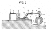
- Fig. 3 is a schematic diagram of a welding machine for welding the turbine rotor.
- the welding machine is used to perform a tungsten inert gas (TIG) welding method.
- the welding machine 8 includes a torch 10 which electrodes 9 are attached to, a weld wire 11 forming the weld 6, and an arm 12 supporting and fixing the torch 10 and the weld wire 11.
- the welding machine 8 further includes a weld power 13 for supplying current of a predetermined value to the electrodes 9, a gas bombe 14 for supplying inert gas to be spouted from around the electrodes 9 so as to suppress oxidization of the weld 6, a positioner 15 for supporting and rotating the turbine rotor, and a wire feeder 16 for feeding the weld wire 11 to the weld 6.
- a power cable 17 extending from the weld power 13 is attached to the electrodes 9 so as to supply the current from the weld power 13 to the electrodes 9.
- a gas hose 18 is attached to the torch 10 for receiving the inert gas supplied from the gas bombe 14.
- a power cable 19 is attached to the turbine rotor so as to generate electric arc between the electrodes 9 and the turbine rotor.
- a signal cable 20 for the positioner is attached to the positioner 15, so that the rotation speed and rotation direction of the positioner 15 is controlled by receiving a control signal from the weld power 13.
- the wire feeder 16 controls the feed speed of the weld wire 11 by receiving a control signal from a signal cable 21 for the wire feeder.
- the welding machine of the present invention can employ a submerged arc welding (SAW) method, a shielded metal are welding method, a metal inert gas (MIG) welding method, as well as the tungsten inert gas (TIG) welding method shown in Fig. 3 , and a combination thereof.
- SAW submerged arc welding
- MIG metal inert gas
- TOG tungsten inert gas
- Fig. 3 shows that the rotor is positioned laterally and welding is performed in the downward direction, the rotor may be positioned vertically and welding may be performed in the horizontal direction.
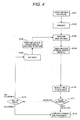
- Fig. 4 shows an example of a flowchart of a welding procedure for welding and connecting a plurality of rotors or rotor parts in the turbine rotor according to the present invention.
- step S101 when an instruction to start a welding procedure is given in step S101, rotors are preheated for relaxation of thermal stress in welding in step S102. Then, in step S103, main welding is performed to weld and connect the rotors together by the welding machine shown in Fig. 3 . In step S104, annealing for stress removal is performed so as to uniformize heat having entered in the weld 6 in the main welding. In step S110, inspection of weld flaws in the weld 6 is performed. In step S111, the flaw is detected.
- step S111 When the size of the flaw is not allowable from the viewpoint of mechanical strength in step S112, the weld 6 is cut in step S108, and then the end face of the rotor is subjected to groove processing in step S109.
- step S113 the connection procedure is completed.
- Fig. 5 shows an example of a flowchart of another welding procedure, which is not based on the example of the present invention. This flowchart further includes steps S105 to S107 between step S104 and step S110 in the flowchart shown in Fig. 4 .
- step S105 the shape of penetration bead is inspected.
- step S106 it is determined whether or not the shape of the penetration bead is compliant with the design drawing.
- the shape is not compliant with the design drawing, it is determined whether or not the shape of the penetration bead is allowable in step S107.
- the weld 6 is cut in step S108, and the end face of the rotor is subjected to the groove processing in step S109. Then, the operation returns to step S103, and the main welding is performed again.
- step S110 When the shape of the penetration bead is determined to be compliant with the design drawing in step S106, or when the shape of the penetration bead is determined to be allowable in step S107, inspection of weld flaws in the weld 6 is performed in step S110. Comparing Figs. 4 with 5, the example of the present invention does not include steps S105 to S107, that is, the inspection step of the shape of the penetration bead and the rewelding step of the penetration bead are not necessary, which can shorten the process time.
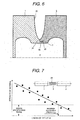
- Fig. 6 shows a section of the vicinity of the weld before welding. The rotor for high pressure and the rotors for low pressure are in contact with each other at the butted portions formed in mating (bitting) shape.
- the contact faces include an outer contact face 31 in the radial direction, an outer contact face 32 in the axial direction, and an inner contact face 33 in the radial direction, which are positioned from the outside in this order.
- the contact face 32 in the axial direction is arranged on the side of the rotor material 2 for low pressure. This is because a heater (not shown) is attached more easily to the rotor material 2 for low pressure in preheating for facile engagement of the butted portions 7.
- the length L 3 of the inner contact face 33 in the radial direction is 1.8 mm. This length is determined based on the result of experiments of a material strength test for the weld joint comprised of both rotor materials and the weld metal 6 (the weld 6) as shown in Fig.
- the lateral axis in Fig. 7 indicates the length of a cutout 34 introduced into the weld joint comprised of the rotor material 1, the rotor material 2, and the weld metal 6.
- the longitudinal axis in Fig. 7 indicates the strength of the material of the weld joint.
- the longitudinal axis also indicates the level of design specifications required for preventing breakage of the weld in operation of the actual machine. The result shows that the material strength of the weld joint tends to decrease with the length of the cutout 34 increasing.
- the length of the cutout 34 should be equal to or less than the maximum allowable length L max .
- the maximum allowable length L max of the cutout 34 was 2.0 mm.
- the inner contact face in the radial direction has a lower limit of the length for supporting the weight of the rotor itself.
- Fig. 8 shows an example of the result of calculation showing the relationship between the length L 3 of the inner contact face 33 in the radial direction and the load stress on the contact face 33.
- the longitudinal axis also indicates the uppermost limit ⁇ max which may cause a breakage of the material.
- the load stress decreases.
- the length L 3 of the inner contact face 33 in the radial direction should be equal to or more than the minimum required length L min .
- the minimum required length L min of the length L 3 of the inner contact face 33 in the radial direction was 0.5 mm.
- the length L 3 of the inner contact face 33 in the radial direction needs to be in the range of 0.5 to 2.0 mm, as represented by the following Equation (1). 0.5 ⁇ L 3 ⁇ 2.0
- Fig. 9 shows a section of the vicinity of the weld after the welding process.
- the weld metal 6 is fused by arc heat discharged from the weld torch, and the welding groove 30 is filled with the weld metal 6, and then the rotor material 1 for high pressure and the rotor material 2 for low pressure are connected metallurgically to each other.
- the weld metal 6 penetrates the rotor material.
- the outer contact face 31 in the radial direction is entirely diminished by the penetration of the weld metal 6.
- the outer contact face 32 in the axial direction is diminished by the penetration of the weld metal 6, but at least a part of the outer contact face 32 remains.
- the length L 2 of the outer contact face 32 in the axial direction was 2.0 mm after the welding. Before the welding, the length L 2 of the outer contact face 32 in the axial direction had been 2.5 mm, and was reduced by 0.5 mm due to the penetration of the weld metal 6. That is, the tip of the penetration portion of the weld metal 6 is located on the outer contact face 32 in the axial direction. The entire inner contact face 33 in the radial direction remains without penetration of the weld metal 6 into it.
- Fig. 10 shows an example of the result of measurement showing the relationship between the amount of heat input Q and the penetration depth D.
- the rotor material is Cr-Mo-V steel and the welding method is TIG.
- the lateral axis indicates the amount of heat input represented by the following Equation (2). This represents the amount of heat per unit length introduced into the material, where the amount is determined by a scanning speed and arc heat generated between the torch and the material.
- Q EI / v wherein E is a voltage value applied between the torch and the material, I is a current value passing through the arc, and v is a scanning speed when a heat source (the torch) moves relatively with respect to the material.
- the longitudinal axis represents the penetration depth D indicating the depth in which the material is fused by the heat input.
- FIG. 11 is a schematic diagram showing the details of the butted portions shown in Fig. 9 .
- the length L 1 of the outer contact face 31 in the radial direction is 2 mm. Therefore, based on the measurement result shown in Fig. 10 , welding is performed by introducing heat Q of about 36 kJ/cm, allowing the weld metal 6 to penetrate only the outer contact face 31 in the radial direction of three contact faces as shown in Fig. 11 .
- Fig. 12 shows a procedure and a physical phenomenon in welding the butted portions together. First, the shape (L 1 , L 2 , L 3 ) of the butted portion is read in (steps 201).
- an amount of heat input Q is selected to satisfy the following Equation (3) (step S203).
- L 1 ⁇ D ⁇ ⁇ ⁇ L 1 2 + L 2 2 At this time, in order not to form penetration beads, the amount of heat input Q should be selected to simultaneously satisfy the Equations (3) and (4).
- L 1 ⁇ D ⁇ L 1 + L 2 Then, the heat for welding is input (step S204) in welding to leave the inner contact face in the radial direction (step S205) and a part of the outer contact face in the axial direction (step S206).
- the penetration beads are not formed (step S207), and then the inspection of the shape is not necessary (step S208).
- This example has the first effect of shortening the manufacturing process time of the welded rotor, and also has the second effect of improving the reliability of strength because no through hole for inspection is required (step S209).
- the center hole of the rotor is sealed (step S210) because no through hole is formed. Air remaining in the center hole of the rotor is heated by the heat input (step 5204) and expanded (step S211). As a result, the weld metal might be easily spouted in a position where the material in the rotor center hole is softened in the root pass welding.
- the heat input expands the material (step S212).
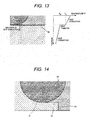
- the schematic diagram of the temperature distribution of the vicinity of the outer contact face in the axial direction will be described below using Fig. 13 .
- the outer contact face 32 in the axial direction intersects the direction of heat transfer at about a right angle.
- the entire contact face 32 is in microscopically inhomogeneous contact with the rotor material 2.
- the contact face 32 is in point or surface contact by microscopic asperities on it. Since some voids exist between the contact face 32 and the rotor material 2, the thermal conductivity is reduced.
- the temperature, gradient becomes discontinuous between the material A, to which heat is first transferred, and the material B, to which heat is next transferred to after the heat transfer via the outer contact face 32 in the axial direction. That is, the material A is at a higher temperature, whereas the material B is at a lower temperature, satisfying the following Equation (5).
- a thermal expansion ⁇ L of the material due to an increase in temperature is represented by the following Equation (6).
- ⁇ L ⁇ ⁇ t - r . t . L
- a a thermal expansion coefficient
- T is a temperature of the material after heating
- r.t. is a room temperature (of about 27 °C)
- L is a length of a heated part.
- Equation (7) is satisfied based on the Equations (5) and (6).
- ⁇ ⁇ L A > ⁇ ⁇ L B This shows that the amount of expansion of the material A is larger than that of the material B.
- the physical phenomenon shown in Fig. 10 is as follows. Expansion of the material A (step S212) compresses the microscopic voids on the outer contact face 32 in the axial direction (step S213), allowing the contact face 32 to be easily brought into intimate contact with the rotor material 2. Thus, the contact face 32 interrupts a route through which the remaining air expanded in the center hole may be spouted (step S214), preventing the spouting of the weld metal of an first layer (step S215).
- the spouting of the weld metal of the first layer leads to a kind of welding flaw, which is subjected to the welding flaw inspection as shown in step S110 of Fig. 4 .
- the prevention of the spouting of the weld metal of the first layer may lead to reduction in flaws of the welding, which can contribute to the second effect of improving the reliability of strength.
- example 2 of the present invention will be described.
- This example is the same as Example 1 except, for the length of the outer contact face 32 in the axial direction, and therefore a description of the same other components as Example 1 will be omitted below.
- the result of a preliminary verification test performed prior to this example will be described below.
- the length L 2 of the outer contact face 32 in the axial direction was 2.5 mm before and after the welding. That is, the penetration tip of the weld metal 6 did not reach the outer contact face 32 in the axial direction. In this case, the effect was not obtained of preventing the spouting of the metal by compression of the outer contact face 32 in the axial direction as described in Fig. 11 .
- example 3 of the present invention will be described.
- This example is the same as Example 1 except for the length of the outer contact face 32 in the axial direction, and therefore a description of the same other components as Example 1 will be omitted below.
- the result, of a preliminary verification test performed prior to this example will be described below.
- the length L 2 of the outer contact face 32 in the axial direction was 2.5 mm before the welding and 0 mm after the welding. That is, the weld metal 6 included the entire area of the outer contact face 32 in the axial direction. In this case, since the outer contact face 32 in the axial direction disappeared, the effect of preventing the spouting of the weld metal was not obtained.
- example 4 of the present invention will be described.
- This example is the same as Example 1 except for the length of the outer contact face 32 in the axial direction, and therefore a description of the same other components as Example 1 will be omitted below.
- the result of a preliminary verification test performed prior to this example will be described below.
- the length L 2 of the outer contact face 32 in the axial direction was 4.0 mm before the welding and was also 4.0 mm after the welding. That is, the penetration tip of the weld metal 6 did not reach the outer contact face 32 in the axial direction. In this case, since the outer contact face 32 in the axial direction disappeared, the effect of preventing the spouting of the metal was not obtained.
- example 5 of the present invention will be described This example is the same as Example 1 except for the length of the outer contact face 32 in the axial direction, and therefore a description of the same other components as Example 1 will be omitted below.
- the result of a preliminary verification test performed prior to this example will be described below.
- the length L 2 of the outer contact face 32 in the axial direction was 3.0 mm before the welding and 0 mm after the welding. That is, the weld metal 6 included the entire area of the outer contact face 32 in the axial direction. In this case, since the outer contact face 32 in the axial direction disappeared, the effect of preventing the spouting of the weld metal was not obtained.
- Example 6 of the present invention will be described.
- Example 2 This example is the same as Example 1 except for a combination of the material and weld wire, and therefore a description of the same other components as Example 1 will be omitted below.
- the rotor 62 for high pressure includes 12 % Cr steel.
- the rotor 61 for low pressure includes Cr-Mo-V steel.
- Table 2 shows chemical compositions (weight percent) of the weld wire and materials constituting the rotors of the turbine rotor, the rest of the compositions being Fe.
- the material of the rotor 62 for high pressure includes 10.04 % Cr and the material of the rotor 61 for low pressure includes 1.13 % Cr.
- the buttering material should include an amount of Cr between the amounts of Cr of both rotors.
- the buttering material applied to the rotor for high pressure was 9% Cr steel.
- the weld wire includes 1.22 % Cr or 2.22 % Cr, which is more than the amounts of the rotor 61 for low pressure, so as not to reduce the strength of the wire even under the heat treatment at a temperature equal to or higher than a last tempering temperature of both rotors.
- Table 2 shows chemical compositions of the typical weld wires. Different combinations of the material and the weld wire do not change the effect shown in Example 1.
- Example 7 of the present invention will be described.
- Example 2 This example is the same as Example 1 except for a combination of the material and weld wire, and therefore a description of the same other components as Example 1 will be omitted below.
- the rotor 62 for high pressure and the rotor 61 for low pressure include 3 to 4% Ni-Cr-Mo-V steel.
- Table 3 shows chemical compositions (weight percent) of the weld wire and materials constituting the rotors of the turbine rotor, the rest of the compositions being Fe.
- each of the material of the rotor 62 for high pressure and the rotor 61 for low pressure includes 3.71 % Ni.
- the weld metal 6 should include an amount of Ni between the amounts of Ni of both rotors.
- the weld metal 6 includes 2.87 % or 3.21 % Ni, which is lower than the amounts of both rotors.
- Table 3 shows chemical compositions of the typical weld wires. Different combinations of the material and the weld wire do not change the effect shown in example 1.
- Fig. 18 is a schematic sectional view of a turbine rotor for the high and low pressure according to the present invention.
- This turbine rotor has the same shape as the turbine rotor of Example 1 shown in Fig. 1 , but the welding position is located at the high- pressure side.
- the weld may be located at the low-pressure side as shown in Fig. 19 .
- the turbine rotor may have plurality of welds as shown in Fig. 20 .
- the weld is preferably located at the most cost-effective position, which is determined based on the pressure and temperature required for the turbine rotor and costs of the rotor materials for high pressure and for low pressure.
- Example 9 of the present invention will be described.
- This example is the same as Example 1 except for the direction of the outer contact face 32 in the axis direction, the direction of the inner contact face 33 in the radial direction, or the both directions of the outer contact face 32 in the axis direction and the inner contact face 33 in the radial direction. Therefore, a description of the same other components as Example 1 will be omitted below.
- Fig. 21 is the same as Example 1 except for the direction of the outer contact face 32 in the axis direction, the direction of the inner contact face 33 in the radial direction, or the both directions of the outer contact face 32 in the axis direction and the inner contact face 33 in the radial direction. Therefore, a description of the same other components as Example 1 will be omitted below.
- FIG. 21 is a schematic diagram showing butted portions in which the outer contact face 32 in the axial direction is inclined such that the outer contact face 32 is directed toward the outside of the rotor on the side of the rotor material 1 for high pressure and also directed toward the inside of the rotor on the side of the rotor material 2 for low pressure. It is not preferable that the contact face 32 is inclined in the reverse direction because the rotor material 1 for high pressure cannot be assembled to the rotor material 2 for low pressure.
- Fig. 22 is a schematic diagram showing butted portions in which the inner contact face 33 in the radial direction is inclined such that the inner contact face 33 is directed toward the rotor material 2 for low pressure on the inner side of the rotor.
- Fig. 23 is a schematic diagram showing butted portions in which both the outer contact face 32 in the axial direction and the inner contact face 33 in the radial direction are inclined.
- the outer contact face 32 is directed toward the outside of the rotor on the side of the rotor material 1 for high pressure and also directed toward the inside of the rotor on the side of the rotor material 2 for low pressure.
- the inner contact face 33 is directed toward the rotor material 2 for low pressure on the inner side of the rotor.
Landscapes
- Engineering & Computer Science (AREA)
- Mechanical Engineering (AREA)
- General Engineering & Computer Science (AREA)
- Turbine Rotor Nozzle Sealing (AREA)
- Butt Welding And Welding Of Specific Article (AREA)
Applications Claiming Priority (1)
| Application Number | Priority Date | Filing Date | Title |
|---|---|---|---|
| JP2008197171A JP2010031812A (ja) | 2008-07-31 | 2008-07-31 | タービンロータ |
Publications (2)
| Publication Number | Publication Date |
|---|---|
| EP2149690A2 true EP2149690A2 (de) | 2010-02-03 |
| EP2149690A3 EP2149690A3 (de) | 2011-02-16 |
Family
ID=41063453
Family Applications (1)
| Application Number | Title | Priority Date | Filing Date |
|---|---|---|---|
| EP09166749A Withdrawn EP2149690A3 (de) | 2008-07-31 | 2009-07-29 | Turbinenrotor |
Country Status (3)
| Country | Link |
|---|---|
| US (1) | US20100028155A1 (de) |
| EP (1) | EP2149690A3 (de) |
| JP (1) | JP2010031812A (de) |
Cited By (4)
| Publication number | Priority date | Publication date | Assignee | Title |
|---|---|---|---|---|
| EP2357054A1 (de) * | 2010-02-12 | 2011-08-17 | General Electric Company | Verfahren zum Horizontalschweißen und Verbindungsstruktur dafür |
| CN102852559A (zh) * | 2011-06-30 | 2013-01-02 | 通用电气公司 | 涡轮盘预制件、其制成的焊接涡轮转子及制造它们的方法 |
| CN104191096A (zh) * | 2014-05-30 | 2014-12-10 | 徐州徐工液压件有限公司 | 液压缸护套焊接结构及加工工艺 |
| EP3466600A1 (de) * | 2017-09-19 | 2019-04-10 | Mitsubishi Heavy Industries, Ltd. | Verfahren zum verbinden von elementen und turbinenkomponenten |
Families Citing this family (9)
| Publication number | Priority date | Publication date | Assignee | Title |
|---|---|---|---|---|
| JP5193960B2 (ja) | 2009-06-30 | 2013-05-08 | 株式会社日立製作所 | タービンロータ |
| JP5553739B2 (ja) * | 2010-12-16 | 2014-07-16 | 株式会社日立製作所 | 溶接構造物 |
| JP5822496B2 (ja) * | 2011-03-23 | 2015-11-24 | 三菱日立パワーシステムズ株式会社 | タービンロータ及びタービンロータの製造方法 |
| JP5979859B2 (ja) | 2011-12-08 | 2016-08-31 | 三菱日立パワーシステムズ株式会社 | バックシールド溶接方法 |
| EP2623252A1 (de) * | 2012-02-06 | 2013-08-07 | Siemens Aktiengesellschaft | Verfahren zur stoffschlüssigen Verbindung zweier Bauteile unter Verwendung von Anformungen zum Manipulieren dieser Bauteile |
| JP5955125B2 (ja) | 2012-06-22 | 2016-07-20 | 三菱日立パワーシステムズ株式会社 | タービンロータ及びその製造方法及び当該タービンロータを用いた蒸気タービン |
| US9388697B2 (en) * | 2012-07-17 | 2016-07-12 | Solar Turbines Incorporated | First stage compressor disk configured for balancing the compressor rotor assembly |
| JP5973870B2 (ja) * | 2012-10-26 | 2016-08-23 | 三菱日立パワーシステムズ株式会社 | 蒸気タービンロータの溶接方法 |
| JP6189737B2 (ja) * | 2013-12-18 | 2017-08-30 | 三菱日立パワーシステムズ株式会社 | 蒸気タービン低圧ロータ及びその製造方法 |
Family Cites Families (16)
| Publication number | Priority date | Publication date | Assignee | Title |
|---|---|---|---|---|
| FR1191293A (fr) * | 1957-03-11 | 1959-10-19 | Bbc Brown Boveri & Cie | Procédé pour la fabrication de rotors de turbines à partir d'éléments réunis les uns aux autres par soudage |
| FR1590720A (de) * | 1968-10-10 | 1970-04-20 | ||
| US4182950A (en) * | 1973-10-11 | 1980-01-08 | Boros Lawrence A | Deep fill welding joint configuration and welding method |
| JPS50158544A (de) * | 1974-06-12 | 1975-12-22 | ||
| CH563833A5 (de) * | 1974-10-28 | 1975-07-15 | Bbc Brown Boveri & Cie | |
| JPH0366485A (ja) * | 1989-07-31 | 1991-03-22 | Komatsu Ltd | 円筒部材の溶接方法 |
| US4962586A (en) * | 1989-11-29 | 1990-10-16 | Westinghouse Electric Corp. | Method of making a high temperature - low temperature rotor for turbines |
| US5172475A (en) * | 1991-12-02 | 1992-12-22 | Westinghouse Electric Corp. | Method for repairing a rotor |
| DE59407600D1 (de) * | 1994-01-29 | 1999-02-18 | Asea Brown Boveri | Verfahren zum Verbinden von Metallteilen mittels Lichtbogen-Schmelzschweissen |
| JP2837110B2 (ja) * | 1995-04-18 | 1998-12-14 | 三菱重工業株式会社 | 急速起動用蒸気タービンロータ |
| JPH10202379A (ja) * | 1997-01-20 | 1998-08-04 | Isuzu Motors Ltd | 溶接構造 |
| JP3999402B2 (ja) * | 1998-06-09 | 2007-10-31 | 三菱重工業株式会社 | 蒸気タービンの異材溶接ロータ |
| US6499946B1 (en) * | 1999-10-21 | 2002-12-31 | Kabushiki Kaisha Toshiba | Steam turbine rotor and manufacturing method thereof |
| JP2001123801A (ja) * | 1999-10-22 | 2001-05-08 | Mitsubishi Heavy Ind Ltd | タービン用ロータ及びその製造方法 |
| JP2005344527A (ja) * | 2004-05-31 | 2005-12-15 | Toshiba Corp | 蒸気タービンロータおよびその製造方法 |
| US20060231531A1 (en) * | 2005-04-13 | 2006-10-19 | General Electric Company | Weld prep joint for electron beam or laser welding |
-
2008
- 2008-07-31 JP JP2008197171A patent/JP2010031812A/ja active Pending
-
2009
- 2009-07-27 US US12/509,537 patent/US20100028155A1/en not_active Abandoned
- 2009-07-29 EP EP09166749A patent/EP2149690A3/de not_active Withdrawn
Cited By (6)
| Publication number | Priority date | Publication date | Assignee | Title |
|---|---|---|---|---|
| EP2357054A1 (de) * | 2010-02-12 | 2011-08-17 | General Electric Company | Verfahren zum Horizontalschweißen und Verbindungsstruktur dafür |
| CN102189349A (zh) * | 2010-02-12 | 2011-09-21 | 通用电气公司 | 水平焊接方法及其接头结构 |
| CN102852559A (zh) * | 2011-06-30 | 2013-01-02 | 通用电气公司 | 涡轮盘预制件、其制成的焊接涡轮转子及制造它们的方法 |
| CN102852559B (zh) * | 2011-06-30 | 2016-03-23 | 通用电气公司 | 涡轮盘预制件、其制成的焊接涡轮转子及制造它们的方法 |
| CN104191096A (zh) * | 2014-05-30 | 2014-12-10 | 徐州徐工液压件有限公司 | 液压缸护套焊接结构及加工工艺 |
| EP3466600A1 (de) * | 2017-09-19 | 2019-04-10 | Mitsubishi Heavy Industries, Ltd. | Verfahren zum verbinden von elementen und turbinenkomponenten |
Also Published As
| Publication number | Publication date |
|---|---|
| JP2010031812A (ja) | 2010-02-12 |
| US20100028155A1 (en) | 2010-02-04 |
| EP2149690A3 (de) | 2011-02-16 |
Similar Documents
| Publication | Publication Date | Title |
|---|---|---|
| US20100028155A1 (en) | Turbine Rotor | |
| EP0212921B2 (de) | Methode um einen Dampfturbinen- oder Generatorrotor zu reparieren | |
| CN104096984B (zh) | 用于焊接用于发电的转子的方法 | |
| JP2008110404A (ja) | フランジにおける開口および隣接欠陥を補修する方法および装置 | |
| TW201341700A (zh) | 蒸汽產生器加熱管修理構件及修理方法 | |
| US20080028866A1 (en) | Method for evaluating the fatigue strength of welded joints | |
| JP2007071198A (ja) | ターボ機械の一体型のブレード付きディスクのブレードを補修する方法、および該方法を実行するための試験片 | |
| JP4951488B2 (ja) | 蒸気タービンロータ及びその製造方法 | |
| US6652677B2 (en) | Process of welding gamma prime-strengthened nickel-base superalloys | |
| CN104096953B (zh) | 用于焊接发电的转子的方法 | |
| CN119124010A (zh) | 异种金属接合接头的检查方法、异种金属接合接头的检查装置、焊接方法以及焊接系统 | |
| JP6204708B2 (ja) | タービンロータ及びこれを用いた蒸気タービン並びに当該タービンロータの製造方法 | |
| Miglietti et al. | Evaluation of platform weld repairs on f-class, stage 1 buckets | |
| Stepanov et al. | Manufacturing and fatigue tests of PF1 coil helium inlet | |
| JP3082279B2 (ja) | 実機の余寿命予測用小型試験片の製作方法 | |
| TWI827418B (zh) | 渦輪機葉片龜裂之修護方法 | |
| CN115229367B (zh) | 一种汽车传动件环形焊缝等焊深闭合控制试验方法、设备及介质 | |
| Totemeier et al. | Cracking of Grade 91 Steel Welds in Longer-Term Service-Case Studies | |
| US11872663B2 (en) | Repair welding method | |
| RU2575896C2 (ru) | Способ сварки роторов для генерации энергии | |
| RU2316065C2 (ru) | Способ изготовления образца-свидетеля сварного соединения тепловыделяющего элемента ядерного реактора (варианты) | |
| JP3007243B2 (ja) | レ形開先多層溶接における裏波溶接ビードの開先斜め側ルート止端部の折れ込み防止方法 | |
| CN121607742A (zh) | 管-管对接垂直环焊缝的焊接方法 | |
| Shelyagin et al. | Development of remotely-controlled equipment and technology for laser welding repair and restoration of performance of NPP steam generators | |
| JP2017035721A (ja) | レーザ溶接継手 |
Legal Events
| Date | Code | Title | Description |
|---|---|---|---|
| PUAI | Public reference made under article 153(3) epc to a published international application that has entered the european phase |
Free format text: ORIGINAL CODE: 0009012 |
|
| 17P | Request for examination filed |
Effective date: 20091211 |
|
| AK | Designated contracting states |
Kind code of ref document: A2 Designated state(s): AT BE BG CH CY CZ DE DK EE ES FI FR GB GR HR HU IE IS IT LI LT LU LV MC MK MT NL NO PL PT RO SE SI SK SM TR |
|
| AX | Request for extension of the european patent |
Extension state: AL BA RS |
|
| PUAL | Search report despatched |
Free format text: ORIGINAL CODE: 0009013 |
|
| AK | Designated contracting states |
Kind code of ref document: A3 Designated state(s): AT BE BG CH CY CZ DE DK EE ES FI FR GB GR HR HU IE IS IT LI LT LU LV MC MK MT NL NO PL PT RO SE SI SK SM TR |
|
| AX | Request for extension of the european patent |
Extension state: AL BA RS |
|
| STAA | Information on the status of an ep patent application or granted ep patent |
Free format text: STATUS: THE APPLICATION HAS BEEN WITHDRAWN |
|
| 18W | Application withdrawn |
Effective date: 20120629 |