EP2149702B1 - Palier d'arbre de rotor d'une éolienne - Google Patents
Palier d'arbre de rotor d'une éolienne Download PDFInfo
- Publication number
- EP2149702B1 EP2149702B1 EP09008904.6A EP09008904A EP2149702B1 EP 2149702 B1 EP2149702 B1 EP 2149702B1 EP 09008904 A EP09008904 A EP 09008904A EP 2149702 B1 EP2149702 B1 EP 2149702B1
- Authority
- EP
- European Patent Office
- Prior art keywords
- bearing
- rotor
- wind turbine
- sleeve
- turbine according
- Prior art date
- Legal status (The legal status is an assumption and is not a legal conclusion. Google has not performed a legal analysis and makes no representation as to the accuracy of the status listed.)
- Not-in-force
Links
Images


Classifications
-
- F—MECHANICAL ENGINEERING; LIGHTING; HEATING; WEAPONS; BLASTING
- F16—ENGINEERING ELEMENTS AND UNITS; GENERAL MEASURES FOR PRODUCING AND MAINTAINING EFFECTIVE FUNCTIONING OF MACHINES OR INSTALLATIONS; THERMAL INSULATION IN GENERAL
- F16C—SHAFTS; FLEXIBLE SHAFTS; ELEMENTS OR CRANKSHAFT MECHANISMS; ROTARY BODIES OTHER THAN GEARING ELEMENTS; BEARINGS
- F16C19/00—Bearings with rolling contact, for exclusively rotary movement
- F16C19/54—Systems consisting of a plurality of bearings with rolling friction
- F16C19/546—Systems with spaced apart rolling bearings including at least one angular contact bearing
- F16C19/547—Systems with spaced apart rolling bearings including at least one angular contact bearing with two angular contact rolling bearings
- F16C19/548—Systems with spaced apart rolling bearings including at least one angular contact bearing with two angular contact rolling bearings in O-arrangement
-
- F—MECHANICAL ENGINEERING; LIGHTING; HEATING; WEAPONS; BLASTING
- F03—MACHINES OR ENGINES FOR LIQUIDS; WIND, SPRING, OR WEIGHT MOTORS; PRODUCING MECHANICAL POWER OR A REACTIVE PROPULSIVE THRUST, NOT OTHERWISE PROVIDED FOR
- F03D—WIND MOTORS
- F03D80/00—Details, components or accessories not provided for in groups F03D1/00 - F03D17/00
- F03D80/70—Bearing or lubricating arrangements
-
- F—MECHANICAL ENGINEERING; LIGHTING; HEATING; WEAPONS; BLASTING
- F16—ENGINEERING ELEMENTS AND UNITS; GENERAL MEASURES FOR PRODUCING AND MAINTAINING EFFECTIVE FUNCTIONING OF MACHINES OR INSTALLATIONS; THERMAL INSULATION IN GENERAL
- F16C—SHAFTS; FLEXIBLE SHAFTS; ELEMENTS OR CRANKSHAFT MECHANISMS; ROTARY BODIES OTHER THAN GEARING ELEMENTS; BEARINGS
- F16C19/00—Bearings with rolling contact, for exclusively rotary movement
- F16C19/22—Bearings with rolling contact, for exclusively rotary movement with bearing rollers essentially of the same size in one or more circular rows, e.g. needle bearings
- F16C19/34—Bearings with rolling contact, for exclusively rotary movement with bearing rollers essentially of the same size in one or more circular rows, e.g. needle bearings for both radial and axial load
- F16C19/36—Bearings with rolling contact, for exclusively rotary movement with bearing rollers essentially of the same size in one or more circular rows, e.g. needle bearings for both radial and axial load with a single row of rollers
- F16C19/364—Bearings with rolling contact, for exclusively rotary movement with bearing rollers essentially of the same size in one or more circular rows, e.g. needle bearings for both radial and axial load with a single row of rollers with tapered rollers, i.e. rollers having essentially the shape of a truncated cone
-
- F—MECHANICAL ENGINEERING; LIGHTING; HEATING; WEAPONS; BLASTING
- F16—ENGINEERING ELEMENTS AND UNITS; GENERAL MEASURES FOR PRODUCING AND MAINTAINING EFFECTIVE FUNCTIONING OF MACHINES OR INSTALLATIONS; THERMAL INSULATION IN GENERAL
- F16C—SHAFTS; FLEXIBLE SHAFTS; ELEMENTS OR CRANKSHAFT MECHANISMS; ROTARY BODIES OTHER THAN GEARING ELEMENTS; BEARINGS
- F16C35/00—Rigid support of bearing units; Housings, e.g. caps, covers
- F16C35/04—Rigid support of bearing units; Housings, e.g. caps, covers in the case of ball or roller bearings
- F16C35/06—Mounting or dismounting of ball or roller bearings; Fixing them onto shaft or in housing
-
- F—MECHANICAL ENGINEERING; LIGHTING; HEATING; WEAPONS; BLASTING
- F05—INDEXING SCHEMES RELATING TO ENGINES OR PUMPS IN VARIOUS SUBCLASSES OF CLASSES F01-F04
- F05B—INDEXING SCHEME RELATING TO WIND, SPRING, WEIGHT, INERTIA OR LIKE MOTORS, TO MACHINES OR ENGINES FOR LIQUIDS COVERED BY SUBCLASSES F03B, F03D AND F03G
- F05B2240/00—Components
- F05B2240/50—Bearings
-
- F—MECHANICAL ENGINEERING; LIGHTING; HEATING; WEAPONS; BLASTING
- F16—ENGINEERING ELEMENTS AND UNITS; GENERAL MEASURES FOR PRODUCING AND MAINTAINING EFFECTIVE FUNCTIONING OF MACHINES OR INSTALLATIONS; THERMAL INSULATION IN GENERAL
- F16C—SHAFTS; FLEXIBLE SHAFTS; ELEMENTS OR CRANKSHAFT MECHANISMS; ROTARY BODIES OTHER THAN GEARING ELEMENTS; BEARINGS
- F16C2229/00—Setting preload
-
- F—MECHANICAL ENGINEERING; LIGHTING; HEATING; WEAPONS; BLASTING
- F16—ENGINEERING ELEMENTS AND UNITS; GENERAL MEASURES FOR PRODUCING AND MAINTAINING EFFECTIVE FUNCTIONING OF MACHINES OR INSTALLATIONS; THERMAL INSULATION IN GENERAL
- F16C—SHAFTS; FLEXIBLE SHAFTS; ELEMENTS OR CRANKSHAFT MECHANISMS; ROTARY BODIES OTHER THAN GEARING ELEMENTS; BEARINGS
- F16C2360/00—Engines or pumps
- F16C2360/31—Wind motors
-
- Y—GENERAL TAGGING OF NEW TECHNOLOGICAL DEVELOPMENTS; GENERAL TAGGING OF CROSS-SECTIONAL TECHNOLOGIES SPANNING OVER SEVERAL SECTIONS OF THE IPC; TECHNICAL SUBJECTS COVERED BY FORMER USPC CROSS-REFERENCE ART COLLECTIONS [XRACs] AND DIGESTS
- Y02—TECHNOLOGIES OR APPLICATIONS FOR MITIGATION OR ADAPTATION AGAINST CLIMATE CHANGE
- Y02E—REDUCTION OF GREENHOUSE GAS [GHG] EMISSIONS, RELATED TO ENERGY GENERATION, TRANSMISSION OR DISTRIBUTION
- Y02E10/00—Energy generation through renewable energy sources
- Y02E10/70—Wind energy
- Y02E10/72—Wind turbines with rotation axis in wind direction
Definitions
- the present invention relates to a wind energy plant with a rotor which is connected via a rotor shaft with a gear or a generator.
- the rotor shaft is mounted via two tapered roller bearings in O arrangement preferably via a bearing housing on a carrier unit of the wind turbine.
- Each of the two tapered roller bearings has an inner ring and an outer ring.
- Out DE 103 51 524 is known a rotor bearing for a wind turbine.
- the rotor bearing is used to transmit Rotorbiege- and -windmomenten, with two tapered roller bearings are provided with housing-fixed outer ring and a downstream planetary gear.
- the illustrated tapered roller bearings are designed as a tapered roller bearing pair, which has an integrally formed outer ring.
- the rolling elements of the tapered roller bearing pair are arranged so that the rotor-side rolling element with a perpendicular to its axis of rotation normal direction of the bearing assembly intersects the axis of rotation of the rotor, while the gear-side rolling element with its perpendicular to its axis of rotation normal direction of the transmission side intersects the axis of rotation of the rotor.
- tapered roller bearings with rotating inner ring are referred to in technical language as a tapered roller bearing in O arrangement.
- the use of the tapered roller bearing in O arrangement with an integrally formed outer ring allows a very compact design for the rotor bearing.
- Out DE 103 92 908 B4 is a wind turbine with a tapered roller bearing assembly is known in which the bearing assembly has a first relative to the rotor axis rotationally fixed to a carrier unit and a second rotatable relative to the rotor axis bearing ring.
- the bearing has three rows of cylindrical bodies, with a row at the front and one row each side of the inner ring.
- WO 2006/000214 A1 is a drive train storage for a wind turbine known, in which a tapered roller bearing pair with split inner ring and integrally formed outer ring is provided.
- a bearing arrangement for a pinion shaft in a transmission is known.
- a bearing assembly for a pinion shaft is proposed, which shows two tapered roller bearings in O arrangement, wherein the pinion shaft is additionally mounted on a cylindrical roller bearing in the transmission housing.
- Figure 37 shows a bearing for a rotor shaft of a wind turbine with two tapered roller bearings in O arrangement, whereby the outer ring is formed in one piece.
- WO 2007/085644 A1 a storage of the rotor shaft for a wind turbine is known, wherein a trained in the manner of a moment bearing second rotor bearing is provided as a set against each other tapered roller bearing pair in O arrangement.
- the bearing clearance of the tapered roller bearings is set via a gearbox-side pin connection.
- Out DE 102 31 948 A1 is a wind turbine with a bearing assembly is known in which a first rotatably fixed to the rotor axis to a support assembly bearing ring cooperates with a second rotatable to the rotor axis and fixed to the rotor hub bearing ring.
- the bearing rings have a front side and two laterally arranged rolling elements.
- Out JP 2007 162 750 a bearing assembly for a wind turbine has become known, in which two tapered roller bearings are mounted in O arrangement on a carrier unit.
- the Tapered roller bearings have an inner ring and an outer ring, wherein the inner rings are fixed to each other via a sleeve in their distance in the axial direction, relative to the longitudinal axis of the rotor shaft.
- the invention has for its object to provide a wind turbine with a bearing assembly for the rotor shaft, which allows the simplest possible adjustment and installation of the bearing.
- the wind turbine according to the invention has a rotor which is connected via a rotor shaft with a gear and a generator.
- the rotor shaft is mounted directly or indirectly via two tapered roller bearings in O arrangement on a carrier unit.
- a separate inner ring and a separate outer ring are provided in each case for each tapered roller bearing.
- the inner rings and the outer rings of the tapered roller bearings are fixed to one another via an adjusting device in their distance in the axial direction relative to the rotor shaft.
- two tapered roller bearings each having a separate inner and outer ring are used, which are spaced apart from one another.
- the setting of the distance between the two tapered roller bearings takes place in an axial direction, wherein the axial direction refers to the rotor shaft or its axis of rotation.
- the adjusting device makes it possible, the tapered roller bearings already in the manufacture prior to assembly on the rotor shaft on the invention set adjustment to the desired level. As a result, the assembly on the rotor shaft is significantly simplified.
- the adjusting device comprises two sleeves, of which a first is arranged between the inner rings and a second between the outer rings of the tapered roller bearings.
- the adjustment device with two sleeves ensures that the distance between the inner rings and between the outer rings, which is necessary for the bearing via the tapered roller bearings, is guaranteed. It is possible that the first sleeve has a different length from the second sleeve.
- the outer rings of the tapered roller bearings each have on their sides facing each other a shoulder or a recess, for example in the form of a groove for receiving an end face of the second sleeve.
- a shoulder or a recess for example in the form of a groove for receiving an end face of the second sleeve.
- groove may be present.
- the inner rings of the tapered roller bearings each have a shoulder or a recess for receiving the first sleeve on their mutually facing sides. This allows, as well as the heels in the outer rings to bring the sleeves in a defined position.
- the sleeves can hereby obtain a smaller (larger) diameter than the bearing seats in the bearing housing (on the rotor shaft), damage to the bearing seats during assembly of the sleeves is avoided.
- the rotor shaft has means for fixing one or both tapered roller bearings on the rotor shaft.
- a shoulder may be provided on the shaft, which serves as an abutment, for example, for the inner ring of the rotor-side tapered roller bearing.
- the inner ring of the rotor-side tapered roller bearing is in this case on its side facing the rotor to the shoulder on the rotor shaft.
- the position of the rotor-side tapered roller bearing on the rotor side Are defined.
- the outer rings of the tapered roller bearings are connected via a bearing housing with the carrier unit.
- the bearing housing is integrally formed and surrounds the outer rings of the tapered roller bearings.
- a respective bearing cap is provided on the rotor side and / or on the transmission side, which is connected to the bearing housing, preferably screwed, is.
- the shoulder on the bearing housing serves, as already the shoulder on the rotor shaft, to set the position of the outer ring of the respective tapered roller bearing in the axial direction on one side.
- the shoulder on the bearing housing may alternatively be replaced by an inserted into the bearing housing spacer sleeve or other means for fixing the outer ring in the axial direction.
- the inner ring of the transmission-side tapered roller bearing is fixed on its side facing the transmission via a shaft nut or other device for applying an axial biasing force in the axial direction.
- the rotor shaft is screwed on the transmission side with a gear flange for connecting the rotor shaft with an input shaft of the transmission.
- the torque is transferred from the rotor via the rotor shaft via the gearbox flange to the downstream gearbox.
- a rotor locking disk is arranged on the transmission side of the rotor shaft, the rotor locking disk abutting the inner ring of the transmission-side tapered-roller bearing directly or indirectly on the transmission side.
- the rotor lock washer has a bore for receiving a locking bolt integrated on the bearing housing.
- the rotor can be fixed in a defined position. Such setting of the rotor is desirable, for example, for assembly and maintenance purposes.
- the rotor locking disk on means for axial bearing fixation, which consist for example of a threaded bore in the Rotorarretiersay and a corresponding pressure screw.
- the pressure screw is located on the transmission side by the threaded bore on the inner ring of the transmission-side tapered roller bearing.
- a force is exerted on the inner ring of the transmission-side tapered roller bearing in the axial direction.
- the tapered roller bearing pair is also adjusted via the pressure screw.
- the locking disk simultaneously serves as means for transmitting the torque from the rotor shaft to the transmission.
- FIGS. 5 and 5a show a rotor shaft bearing according to the invention, the FIGS. 1 to 4 . 4a serve for a more detailed explanation.
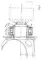
- FIG. 1 shows a section of a rotor hub 10 which is connected via a locking disc 12 with a rotor shaft 14, wherein the locking disc is clamped between the rotor shaft and rotor hub.
- the connection is made by means of screws (not shown) in threaded bores 16 which extend on the rotor side through the rotor hub 10 and the locking disk 12 into the rotor shaft 14.
- a gear flange 18 is also screwed on the front side of the rotor shaft 14 via screws 20 (not shown).
- the tapered roller bearing 24 is the rotor-side tapered roller bearing, wherein the tapered roller bearing 26 is considered as the transmission-side tapered roller bearing.
- the inner rings 28, 30 are arranged offset in the axial direction of the rotor shaft relative to the outer rings 32, 34.
- the inner ring 28 of the rotor-side tapered roller bearing is offset in the direction of the rotor relative to the outer ring 32.
- the inner ring 30 of the gear-side tapered roller bearing 26 is offset from the gear towards the outer ring 34 of the transmission-side tapered roller bearing.
- a first sleeve 36 is inserted between the inner rings 28 and 30 of the tapered roller bearings 24 and 26, a first sleeve 36 is inserted.
- the first sleeve 36 abuts against the rotor shaft 14, wherein the sleeve can rest completely or in sections on the rotor shaft.
- the sleeve 36 defines the distance between the inner rings 28 and 30.
- a second sleeve 38 is arranged.
- the sleeves 36 and 38 have a different length, wherein the difference in length between these sleeves is set so that the inner ring and outer ring occupy the defined position to each other.
- the sleeves 36 and 38 are cut to size accurate to about 1/100 mm.
- the outer rings 32, 34 are of a bearing housing 40 (see. Fig. 1 enclosed below).
- the bearing housing 40 has in the in FIG. 1 illustrated embodiment, an inner surface against which the outer sides of the outer rings 32, 34.
- the second sleeve 38 may rest on the inner surface or, alternatively, abut in sections on the inner surface of the bearing housing.
- an axial bore 42 is provided in the bearing housing, in which via a screw (not shown), a rotor-side bearing cap 44 is screwed.
- the bearing housing 40 is also provided with a bore 48 through which a bearing cap 46 is bolted to the bearing housing 40 (screws not shown).
- the bearing caps 44, 46 have on their facing the tapered roller bearings inside each one projecting in the axial direction of the shoulder, which bears against the outer rings of the tapered roller bearings.
- a shaft nut 50 on a threaded portion 51 provided on the gear-side end of the rotor shaft 14 serves to clamp the bearing inner rings and the first sleeve 36 in a defined manner.
- the detailed view of Figure 1a shows the shaft nut 50 from the upper portion of FIG. 1 .
- the process of applying a defined preload force is referred to as: Pull the inner rings and the sleeve to block.
- a shaft sleeve 55 is provided, which transmits the biasing force of the shaft nut 50.
- the rotor-side tapered roller bearing is positioned with the rotor side down. Subsequently, the outer sleeve 38 is placed. The gear-side tapered roller bearing is subsequently placed on the outer sleeve. To set the bearing of the transmission side bearing inner ring is then loaded with a defined axial force and measured the distance between the two bearing inner rings. Based on the measured distance, the inner sleeve 36 is manufactured with the required excess for adjustment with bearing clearance or undersize for adjustment with bias. Due to the exact manufacture of the inner sleeve, the tapered roller bearings are adjusted to each other after application of an axial force.
- FIG. 1 has the rotor shaft 14 at its end facing the rotor 10, a shoulder 52 on which the inner ring 28 of the rotor-side tapered roller bearing 24 is applied to the transmission side. Via the shoulder 52 on the rotor shaft 14 in cooperation with the first sleeve 36, the shaft sleeve 55 and the shaft nut 50, the position of the inner rings 28 and 30 is fixed on the rotor shaft 14.
- FIG. 2 shows an alternative embodiment of the storage. Subsequently, the same components are provided with the same reference numerals.
- the inner ring of the rotor-side tapered roller bearing 24 is again on the transmission side to a shoulder 52 of the rotor shaft 14 at.
- the bearing housing 41 has a shoulder 53 on the transmission side, on which the outer ring of the gear-side tapered roller bearing 26 rests on the rotor side. In this way, the position of the outer ring of the transmission-side bearing is additionally determined.
- the transmission-side bearing cap 47 is not applied to the outer ring 34, but is spaced therefrom in the axial direction.
- the assembly can be adjusted to the rotor shaft 14 by the sleeves 36 and 38 are previously matched precisely to each other, so that the inner rings and the outer rings have the intended distance from each other.
- FIG. 3 shows a further embodiment of the rotor bearing.
- the bearing housing 40 in the third embodiment has different design than the embodiment FIG. 2 no shoulder at the rotor end. Rather, the outer rings 34 and 32 of the tapered roller bearings abut on a portion of the inner surface of the bearing housing 40.
- the area of the inner surface of the bearing housing between the outer rings 32 and 34 may in this case have a depression, as well as the area on the rotor shaft 14 between the inner rings 28, 30.
- FIG. 3a shown Here, a spacer sleeve 60 is placed on the rotor shaft 14.
- the spacer sleeve 60 can be fixed axially on the rotor side by the locking disk 12, the rotor hub directly or another rotating component in the rotor-side direction. On the transmission side, the spacer sleeve 60 supports the inner ring 28 of the rotor-side tapered roller bearing. The spacer sleeve 60 thus performs the same task as the shoulder 52 according to the embodiments FIGS. 1 and 2 and also avoids that the rotor shaft 17 receives a larger diameter in the form of a shaft shoulder and thus a jump in stiffness.
- FIGS. 4 and 4a show a further example of storage, in which again the same components are provided with the same reference numerals.
- the tapered roller bearings 24 and 26 are arranged on the rotor-side or gear-side end of the rotor shaft 14.
- the rotor-side tapered roller bearing 24 rests with its inner ring 28 on the rotor side on a shaft shoulder 52.
- the gear-side tapered roller bearing 26 is located with his
- the outer rings 32 and 34 of the tapered roller bearings are arranged within the bearing housing 40. Between the outer rings 32 and 34, the sleeve 38 is arranged, which also bears against the bearing housing 40.
- a rotor locking unit 64 is provided, which has a locking pin 66, by means of which the rotor shaft and the rotor can be fixed relative to the rotor locking disk 62. For this purpose, the bolt 66 is advanced so that it engages in a bore 68 in the rotor locking disk 62.
- the Rotorarretiersay 62 has a threaded bore 70 through which a pressure screw (not shown) can be screwed to apply a defined force on the inner ring 30 of the gear-side tapered roller bearing 26 and to fix this simultaneously in its axial position.
- a pressure screw (not shown) can be screwed to apply a defined force on the inner ring 30 of the gear-side tapered roller bearing 26 and to fix this simultaneously in its axial position.
- FIGS. 5 and 5a show an embodiment of the storage according to the invention, in which the inside of the outer rings 32 and 34 are each provided with a shoulder 72.
- the second sleeve 38 rests between the outer rings 32 and 34 in the paragraphs 72, respectively.
- the inner rings 28, 30 of the tapered roller bearings are provided with shoulders 74 against which the first sleeve 36 rests.
- paragraphs 72, 74 enclose the sleeves 36, 38 relative to the pair of bearings outside or otherwise shaped recesses for receiving the sleeves 36, 38 may be provided if they adapted to the geometry of the sleeves.
Landscapes
- Engineering & Computer Science (AREA)
- General Engineering & Computer Science (AREA)
- Mechanical Engineering (AREA)
- Life Sciences & Earth Sciences (AREA)
- Sustainable Development (AREA)
- Sustainable Energy (AREA)
- Chemical & Material Sciences (AREA)
- Combustion & Propulsion (AREA)
- Rolling Contact Bearings (AREA)
- Mounting Of Bearings Or Others (AREA)
Claims (20)
- Éolienne muni d'un rotor qui est connecté par un arbre de rotor (14) à une transmission (22) et/ou un générateur, l'arbre de rotor (14) étant attaché sur une unité de support via deux roulements à rouleaux coniques (24, 26) dans une disposition en O, chaque roulement à rouleaux coniques (24, 26) comportant une bague intérieure et une bague extérieure, les bagues intérieures (28, 30) et les bagues extérieures (32, 34) sont fixées entre elles par deux manchons (36, 38) dans leur distance dans la direction axiale par référence à l'axe de rotation de l'arbre de rotor (14), dont un premier manchon (36) est agencé entre les bagues intérieures (28, 30) et un second manchon (38) est agencé entre les bagues extérieures (32, 34) des roulements à rouleaux coniques (24, 26), les bagues extérieures (32, 34) comportant sur leurs faces orientant l'une sur l'autre un épaulement (72) ou un évidement pour la attachement d'une extrémité côté frontal du second manchon (38).
- Éolienne selon la revendication 1, caractérisée en ce que les bagues extérieures (32, 34) des roulements à rouleaux coniques (24, 26) sont connectées par un logement de roulement (40, 41) à l'unité de support.
- Éolienne selon la revendication 2, caractérisée en ce que le second manchon (38) comporte un diamètre inférieur à celui des chaises de roulement dans le logement de roulement.
- Éolienne selon une des revendications 1 à 3, caractérisée en ce que l'évidement pour la attachement d'une extrémité côté frontal du second manchon (38) dans les faces orientant l'une sur l'autre des bagues extérieures (32, 34) est une rainure.
- Éolienne selon une des revendications 1 à 3, caractérisée en ce que les épaulements (72) des bagues extérieures (32, 34) par référence à la paire de roulements des deux roulements à rouleaux coniques (24, 26) sont agencés rentrés.
- Éolienne selon une des revendications 1 à 3, caractérisée en ce que les épaulements (72) des bagues extérieures (32, 34) par référence à la paire de roulements des deux roulements à rouleaux coniques (24, 26) sont agencés en saillie et entourent le second manchon (38).
- Éolienne selon une des revendications 1 à 6, caractérisée en ce que les bagues intérieures (28, 30) sur leurs faces orientant l'une sur l'autre comportant respectivement un épaulement (74) ou un évidement pour la attachement du premier manchon (36).
- Éolienne muni d'un rotor qui est connecté par un arbre de rotor (14) à une transmission (22) et/ou un générateur, l'arbre de rotor (14) étant attaché sur une unité de support via deux roulements à rouleaux coniques (24, 26) dans une disposition en O, chaque roulement à rouleaux coniques (24, 26) compartant une bague intérieure et une bague extérieure, les bagues intérieures (28, 30) et les bagues extérieures (32, 34) étant fixées entre elles par deux manchons (36, 38) dans leur distance dans la direction axiale par référence à l'axe de rotation de l'arbre de rotor (14), dont un premier manchon (36) est agencé entre les bagues intérieures (28, 30) et un second manchon (38) est agencé entre les bagues extérieures (32, 34) des roulements à rouleaux coniques (24, 26), les bagues intérieures (28, 30) comportant sur leurs faces orientant l'une sur l'autre un épaulement (74) ou un évidement pour la attachement du premier manchon (36).
- Éolienne selon la revendication 8, caractérisée en ce que le premier manchon (36) comporte un diamètre supérieur à celui des chaises de roulement sur l'arbre de rotor.
- Éolienne selon les revendications 8 ou 9, caractérisée en ce que les épaulements (74) des bagues intérieures (28, 30) par référence à la paire de roulements des deux roulements à rouleaux coniques (24, 26) sont agencés rentrés.
- Éolienne selon les revendications 8 ou 9, caractérisée en ce que les épaulements (74) des bagues intérieures (28, 30) par référence à la paire de roulements des deux roulements à rouleaux coniques (24, 26) sont agencés en saillie et entourent le premier manchon (36).
- Éolienne selon une des revendications 9 à 11, caractérisée en ce que les bagues extérieures (32, 34) sur leurs faces orientant l'une sur l'autre comportant respectivement un épaulement (72) ou un évidement pour la attachement d'une extrémité côté frontal du second manchon (38).
- Éolienne selon une des revendications 8 à 12, caractérisée en ce que les bagues extérieures (32, 34) des roulements à rouleaux coniques (24, 26) sont connectées par un logement de roulement (40, 41) à l'unité de support.
- Éolienne selon une des revendications 2 à 7 ou 13, caractérisée en ce que côté rotor et/ou côté transmission est prévu un chapeau de roulement (44, 46, 47) qui est connecté au logement de roulement (40, 41).
- Éolienne selon une des revendications 2 à 7, 13 ou 14, caractérisée en ce que le logement de roulement côté transmission ou côté rotor comporte un épaulement (53) contre lequel s'appuie la bague extérieure (34) du roulement à rouleaux coniques (26) côté transmission sur sa face dirigée vers la transmission et/ou la bague extérieure (32) du roulement à rouleaux coniques (24) côté rotor sur sa face dirigée vers le rotor.
- Éolienne selon une des revendications 1 à 15, caractérisée en ce que la bague intérieure (30) du roulement à rouleaux coniques côté transmission sur sa face dirigée vers la transmission est fixée dans la direction axiale par des moyens d'application d'une force de précontrainte axiale.
- Éolienne selon la revendication 16, caractérisée en ce qu'un écrou d'arbre (50) est prévu comme moyen d'application d'une force de précontrainte axiale.
- Éolienne selon la revendication 17, caractérisée en ce que l'écrou d'arbre (50) est vissé sur un segment fileté (51) à l'extrémité côté transmission de l'arbre de rotor.
- Éolienne selon une des revendications 1 à 18, caractérisée en ce qu'un disque d'arrêt de rotor (62) est agencé côté transmission de l'arbre de rotor (14), le disque d'arrêt de rotor (62) s'appuyant directement ou indirectement côté transmission contre la bague intérieure (30) du roulement à rouleaux coniques (26) côté transmission.
- Éolienne selon la revendication 19, caractérisée en ce que le disque d'arrêt de rotor (62) comporte des moyens de fixation axiale de roulement.
Applications Claiming Priority (1)
| Application Number | Priority Date | Filing Date | Title |
|---|---|---|---|
| DE102008036217A DE102008036217A1 (de) | 2008-08-02 | 2008-08-02 | Windenergieanlage mit einem Rotor |
Publications (3)
| Publication Number | Publication Date |
|---|---|
| EP2149702A2 EP2149702A2 (fr) | 2010-02-03 |
| EP2149702A3 EP2149702A3 (fr) | 2012-01-18 |
| EP2149702B1 true EP2149702B1 (fr) | 2013-04-17 |
Family
ID=40910890
Family Applications (1)
| Application Number | Title | Priority Date | Filing Date |
|---|---|---|---|
| EP09008904.6A Not-in-force EP2149702B1 (fr) | 2008-08-02 | 2009-07-08 | Palier d'arbre de rotor d'une éolienne |
Country Status (3)
| Country | Link |
|---|---|
| US (1) | US8169095B2 (fr) |
| EP (1) | EP2149702B1 (fr) |
| DE (1) | DE102008036217A1 (fr) |
Families Citing this family (10)
| Publication number | Priority date | Publication date | Assignee | Title |
|---|---|---|---|---|
| DE102011012437A1 (de) | 2011-02-25 | 2012-08-30 | Powerwind Gmbh | Triebstranganordnung für eine Windenergieanlage |
| DE102011005498A1 (de) * | 2011-03-14 | 2012-09-20 | Aktiebolaget Skf | Lagerkonzept mit Wickelrohren |
| EP2710271B1 (fr) | 2012-02-02 | 2014-12-03 | Eolotec GmbH | Unité de palier d'une éolienne |
| DE202013012054U1 (de) * | 2012-04-13 | 2015-02-23 | Eolotec Gmbh | Lageranordnung einer Windkraftanlage |
| DE102012221255A1 (de) | 2012-11-21 | 2014-05-22 | Eolotec Gmbh | Lagereinheit für eine Windkraftmaschine |
| US11384729B2 (en) * | 2016-05-11 | 2022-07-12 | Crossed Arrows Ranch, Inc. | Wind turbine |
| EP3577341A1 (fr) | 2017-01-31 | 2019-12-11 | Siemens Gamesa Renewable Energy A/S | Logement de palier monté axialement et éolienne dotée du logement de palier monté axialement |
| CN110311710B (zh) * | 2019-06-05 | 2020-12-11 | 西北大学 | 一种窄带电力载波网络控制器 |
| DK4043723T3 (da) * | 2021-02-11 | 2024-11-18 | Siemens Gamesa Renewable Energy Innovation & Technology SL | Drivenhedssamling |
| CN116906274B (zh) * | 2022-06-29 | 2023-12-19 | 北京金风科创风电设备有限公司 | 传动系统及风力发电机组 |
Family Cites Families (12)
| Publication number | Priority date | Publication date | Assignee | Title |
|---|---|---|---|---|
| US3741614A (en) * | 1971-08-27 | 1973-06-26 | Timken Co | Roller bearings |
| US4565929A (en) * | 1983-09-29 | 1986-01-21 | The Boeing Company | Wind powered system for generating electricity |
| US6418613B1 (en) * | 1998-04-09 | 2002-07-16 | John E. Rode | Bearing assembly adjustable spacer and system for adjusting the same |
| JP2003336631A (ja) * | 2002-05-22 | 2003-11-28 | Koyo Seiko Co Ltd | 自動調心軸受 |
| US7186083B2 (en) * | 2002-06-06 | 2007-03-06 | Elliott Bayly | Wind energy conversion device |
| DE10231948A1 (de) * | 2002-07-15 | 2004-01-29 | Ge Wind Energy Gmbh | Windenergieanlage und Lageranordnung dafür |
| DE10351524A1 (de) | 2002-11-05 | 2004-08-12 | Roland Weitkamp | Rotorlagerung für eine Windenergieanlage |
| CN100559043C (zh) | 2004-06-25 | 2009-11-11 | 维斯塔斯风力系统有限公司 | 风轮机驱动组件 |
| US7154193B2 (en) * | 2004-09-27 | 2006-12-26 | General Electric Company | Electrical machine with double-sided stator |
| GB0500390D0 (en) | 2005-01-10 | 2005-02-16 | Hansen Transmissions Int | Bearing assembly |
| JP2007162750A (ja) * | 2005-12-09 | 2007-06-28 | Ntn Corp | 転がり軸受および風力発電機の主軸支持構造 |
| DE102006004096A1 (de) * | 2006-01-28 | 2007-08-02 | Lohmann & Stolterfoht Gmbh | Antriebsstrang zwischen einem Rotor und einem Getriebe einer Windenergieanlage |
-
2008
- 2008-08-02 DE DE102008036217A patent/DE102008036217A1/de not_active Ceased
- 2008-11-25 US US12/277,725 patent/US8169095B2/en not_active Expired - Fee Related
-
2009
- 2009-07-08 EP EP09008904.6A patent/EP2149702B1/fr not_active Not-in-force
Also Published As
| Publication number | Publication date |
|---|---|
| US20100026005A1 (en) | 2010-02-04 |
| US8169095B2 (en) | 2012-05-01 |
| DE102008036217A1 (de) | 2010-02-04 |
| EP2149702A3 (fr) | 2012-01-18 |
| EP2149702A2 (fr) | 2010-02-03 |
Similar Documents
| Publication | Publication Date | Title |
|---|---|---|
| EP2149702B1 (fr) | Palier d'arbre de rotor d'une éolienne | |
| EP3502468B1 (fr) | Éolienne pourvue de chaîne cinématique | |
| EP2029906B1 (fr) | Procédéde fabrication d'un roulement à billes à contact oblique précontraint axialement sur plusieurs rangs | |
| EP3973200B1 (fr) | Nacelle pour une éolienne | |
| EP3942189A1 (fr) | Palier de glissement | |
| EP4038271A1 (fr) | Pale de rotor d'éolienne, manchon de montage et procédé de liaison de deux segments de pale de rotor | |
| AT524464B1 (de) | Verfahren zum Zusammenbau einer Rotorlagerung einer Windkraftanlage | |
| WO2020164653A1 (fr) | Vis d'entraînement à roulement planétaire | |
| EP3550140A1 (fr) | Support de machine pour éolienne | |
| EP4314579A1 (fr) | Procédé pour appliquer une précontrainte de palier sur un ensemble palier et unité de palier | |
| EP3084269A1 (fr) | Fixation et/ou serrage d'un axe de satellite | |
| DE102007019881A1 (de) | Wälzlager sowie Lagerungsanordnung mit Wälzlager | |
| DE10141457A1 (de) | Einstellanordnung für Axialspiel und Vorbelastung bei Lagern | |
| EP3489534B1 (fr) | Dispositif de précontrainte de palier pour une unité de palier grand ainsi qu'unité de palier grand | |
| DE102008036223A1 (de) | Lageranordnung und Verfahren zur Montage einer montagefertigen Lagereinheit darin | |
| DE102014226145A1 (de) | Rotorseitig verschraubter Planetenbolzen | |
| DE102015208379B4 (de) | Verbrennungskraftmaschine | |
| WO2010037371A1 (fr) | Raccord rotatif pour une éolienne, notamment un palier à roulement doté d'au moins deux rangées de rouleaux et de trois bagues de roulement concentriques | |
| DE102010054948A1 (de) | Lageranordnung | |
| DE102014005415B4 (de) | Lageranordnung für ein Getriebe und Verfahren zum Einstellen der Vorspannung einer Lageranordnung | |
| WO2007099110A1 (fr) | Roulement à billes à portée oblique à précontrainte axiale à plusieurs rangées et procédé de fabrication de celui-ci | |
| DE102007023951A1 (de) | Lagerung eines Stirnrades in einem Getriebe | |
| WO2008064836A1 (fr) | Servomoteur de construction courte avec engrenage d'angle | |
| DE102018003437A1 (de) | Windenergieanlage und Verfahren zur Montage einer Windenergieanlage | |
| EP2450584A2 (fr) | Agencement de palier pour un arbre |
Legal Events
| Date | Code | Title | Description |
|---|---|---|---|
| PUAI | Public reference made under article 153(3) epc to a published international application that has entered the european phase |
Free format text: ORIGINAL CODE: 0009012 |
|
| AK | Designated contracting states |
Kind code of ref document: A2 Designated state(s): AT BE BG CH CY CZ DE DK EE ES FI FR GB GR HR HU IE IS IT LI LT LU LV MC MK MT NL NO PL PT RO SE SI SK SM TR |
|
| AX | Request for extension of the european patent |
Extension state: AL BA RS |
|
| PUAL | Search report despatched |
Free format text: ORIGINAL CODE: 0009013 |
|
| AK | Designated contracting states |
Kind code of ref document: A3 Designated state(s): AT BE BG CH CY CZ DE DK EE ES FI FR GB GR HR HU IE IS IT LI LT LU LV MC MK MT NL NO PL PT RO SE SI SK SM TR |
|
| AX | Request for extension of the european patent |
Extension state: AL BA RS |
|
| RIC1 | Information provided on ipc code assigned before grant |
Ipc: F03D 11/00 20060101AFI20111215BHEP |
|
| 17P | Request for examination filed |
Effective date: 20120718 |
|
| GRAP | Despatch of communication of intention to grant a patent |
Free format text: ORIGINAL CODE: EPIDOSNIGR1 |
|
| GRAS | Grant fee paid |
Free format text: ORIGINAL CODE: EPIDOSNIGR3 |
|
| GRAA | (expected) grant |
Free format text: ORIGINAL CODE: 0009210 |
|
| AK | Designated contracting states |
Kind code of ref document: B1 Designated state(s): AT BE BG CH CY CZ DE DK EE ES FI FR GB GR HR HU IE IS IT LI LT LU LV MC MK MT NL NO PL PT RO SE SI SK SM TR |
|
| REG | Reference to a national code |
Ref country code: GB Ref legal event code: FG4D Free format text: NOT ENGLISH |
|
| REG | Reference to a national code |
Ref country code: CH Ref legal event code: EP |
|
| REG | Reference to a national code |
Ref country code: IE Ref legal event code: FG4D Free format text: LANGUAGE OF EP DOCUMENT: GERMAN |
|
| REG | Reference to a national code |
Ref country code: AT Ref legal event code: REF Ref document number: 607457 Country of ref document: AT Kind code of ref document: T Effective date: 20130515 |
|
| REG | Reference to a national code |
Ref country code: DE Ref legal event code: R096 Ref document number: 502009006854 Country of ref document: DE Effective date: 20130613 |
|
| REG | Reference to a national code |
Ref country code: LT Ref legal event code: MG4D |
|
| REG | Reference to a national code |
Ref country code: NL Ref legal event code: VDEP Effective date: 20130417 |
|
| PG25 | Lapsed in a contracting state [announced via postgrant information from national office to epo] |
Ref country code: ES Free format text: LAPSE BECAUSE OF FAILURE TO SUBMIT A TRANSLATION OF THE DESCRIPTION OR TO PAY THE FEE WITHIN THE PRESCRIBED TIME-LIMIT Effective date: 20130728 Ref country code: IS Free format text: LAPSE BECAUSE OF FAILURE TO SUBMIT A TRANSLATION OF THE DESCRIPTION OR TO PAY THE FEE WITHIN THE PRESCRIBED TIME-LIMIT Effective date: 20130817 Ref country code: GR Free format text: LAPSE BECAUSE OF FAILURE TO SUBMIT A TRANSLATION OF THE DESCRIPTION OR TO PAY THE FEE WITHIN THE PRESCRIBED TIME-LIMIT Effective date: 20130718 Ref country code: PT Free format text: LAPSE BECAUSE OF FAILURE TO SUBMIT A TRANSLATION OF THE DESCRIPTION OR TO PAY THE FEE WITHIN THE PRESCRIBED TIME-LIMIT Effective date: 20130819 Ref country code: LT Free format text: LAPSE BECAUSE OF FAILURE TO SUBMIT A TRANSLATION OF THE DESCRIPTION OR TO PAY THE FEE WITHIN THE PRESCRIBED TIME-LIMIT Effective date: 20130417 Ref country code: FI Free format text: LAPSE BECAUSE OF FAILURE TO SUBMIT A TRANSLATION OF THE DESCRIPTION OR TO PAY THE FEE WITHIN THE PRESCRIBED TIME-LIMIT Effective date: 20130417 Ref country code: SE Free format text: LAPSE BECAUSE OF FAILURE TO SUBMIT A TRANSLATION OF THE DESCRIPTION OR TO PAY THE FEE WITHIN THE PRESCRIBED TIME-LIMIT Effective date: 20130417 Ref country code: NO Free format text: LAPSE BECAUSE OF FAILURE TO SUBMIT A TRANSLATION OF THE DESCRIPTION OR TO PAY THE FEE WITHIN THE PRESCRIBED TIME-LIMIT Effective date: 20130717 Ref country code: SI Free format text: LAPSE BECAUSE OF FAILURE TO SUBMIT A TRANSLATION OF THE DESCRIPTION OR TO PAY THE FEE WITHIN THE PRESCRIBED TIME-LIMIT Effective date: 20130417 |
|
| PG25 | Lapsed in a contracting state [announced via postgrant information from national office to epo] |
Ref country code: LV Free format text: LAPSE BECAUSE OF FAILURE TO SUBMIT A TRANSLATION OF THE DESCRIPTION OR TO PAY THE FEE WITHIN THE PRESCRIBED TIME-LIMIT Effective date: 20130417 Ref country code: CY Free format text: LAPSE BECAUSE OF FAILURE TO SUBMIT A TRANSLATION OF THE DESCRIPTION OR TO PAY THE FEE WITHIN THE PRESCRIBED TIME-LIMIT Effective date: 20130417 Ref country code: PL Free format text: LAPSE BECAUSE OF FAILURE TO SUBMIT A TRANSLATION OF THE DESCRIPTION OR TO PAY THE FEE WITHIN THE PRESCRIBED TIME-LIMIT Effective date: 20130417 Ref country code: HR Free format text: LAPSE BECAUSE OF FAILURE TO SUBMIT A TRANSLATION OF THE DESCRIPTION OR TO PAY THE FEE WITHIN THE PRESCRIBED TIME-LIMIT Effective date: 20130417 Ref country code: BG Free format text: LAPSE BECAUSE OF FAILURE TO SUBMIT A TRANSLATION OF THE DESCRIPTION OR TO PAY THE FEE WITHIN THE PRESCRIBED TIME-LIMIT Effective date: 20130717 |
|
| PLBI | Opposition filed |
Free format text: ORIGINAL CODE: 0009260 |
|
| BERE | Be: lapsed |
Owner name: NORDEX ENERGY G.M.B.H. Effective date: 20130731 |
|
| PG25 | Lapsed in a contracting state [announced via postgrant information from national office to epo] |
Ref country code: EE Free format text: LAPSE BECAUSE OF FAILURE TO SUBMIT A TRANSLATION OF THE DESCRIPTION OR TO PAY THE FEE WITHIN THE PRESCRIBED TIME-LIMIT Effective date: 20130417 Ref country code: SK Free format text: LAPSE BECAUSE OF FAILURE TO SUBMIT A TRANSLATION OF THE DESCRIPTION OR TO PAY THE FEE WITHIN THE PRESCRIBED TIME-LIMIT Effective date: 20130417 Ref country code: CZ Free format text: LAPSE BECAUSE OF FAILURE TO SUBMIT A TRANSLATION OF THE DESCRIPTION OR TO PAY THE FEE WITHIN THE PRESCRIBED TIME-LIMIT Effective date: 20130417 Ref country code: DK Free format text: LAPSE BECAUSE OF FAILURE TO SUBMIT A TRANSLATION OF THE DESCRIPTION OR TO PAY THE FEE WITHIN THE PRESCRIBED TIME-LIMIT Effective date: 20130417 |
|
| PLAX | Notice of opposition and request to file observation + time limit sent |
Free format text: ORIGINAL CODE: EPIDOSNOBS2 |
|
| 26 | Opposition filed |
Opponent name: AKTIEBOLAGET SKF AB Effective date: 20140117 |
|
| PG25 | Lapsed in a contracting state [announced via postgrant information from national office to epo] |
Ref country code: MC Free format text: LAPSE BECAUSE OF FAILURE TO SUBMIT A TRANSLATION OF THE DESCRIPTION OR TO PAY THE FEE WITHIN THE PRESCRIBED TIME-LIMIT Effective date: 20130417 Ref country code: NL Free format text: LAPSE BECAUSE OF FAILURE TO SUBMIT A TRANSLATION OF THE DESCRIPTION OR TO PAY THE FEE WITHIN THE PRESCRIBED TIME-LIMIT Effective date: 20130417 Ref country code: RO Free format text: LAPSE BECAUSE OF FAILURE TO SUBMIT A TRANSLATION OF THE DESCRIPTION OR TO PAY THE FEE WITHIN THE PRESCRIBED TIME-LIMIT Effective date: 20130417 |
|
| REG | Reference to a national code |
Ref country code: CH Ref legal event code: PL |
|
| REG | Reference to a national code |
Ref country code: DE Ref legal event code: R026 Ref document number: 502009006854 Country of ref document: DE Effective date: 20140117 |
|
| REG | Reference to a national code |
Ref country code: IE Ref legal event code: MM4A |
|
| REG | Reference to a national code |
Ref country code: FR Ref legal event code: ST Effective date: 20140331 |
|
| PG25 | Lapsed in a contracting state [announced via postgrant information from national office to epo] |
Ref country code: BE Free format text: LAPSE BECAUSE OF NON-PAYMENT OF DUE FEES Effective date: 20130731 Ref country code: LI Free format text: LAPSE BECAUSE OF NON-PAYMENT OF DUE FEES Effective date: 20130731 Ref country code: CH Free format text: LAPSE BECAUSE OF NON-PAYMENT OF DUE FEES Effective date: 20130731 |
|
| PG25 | Lapsed in a contracting state [announced via postgrant information from national office to epo] |
Ref country code: FR Free format text: LAPSE BECAUSE OF NON-PAYMENT OF DUE FEES Effective date: 20130731 |
|
| PLAF | Information modified related to communication of a notice of opposition and request to file observations + time limit |
Free format text: ORIGINAL CODE: EPIDOSCOBS2 |
|
| PG25 | Lapsed in a contracting state [announced via postgrant information from national office to epo] |
Ref country code: IE Free format text: LAPSE BECAUSE OF NON-PAYMENT OF DUE FEES Effective date: 20130708 |
|
| PLBB | Reply of patent proprietor to notice(s) of opposition received |
Free format text: ORIGINAL CODE: EPIDOSNOBS3 |
|
| PG25 | Lapsed in a contracting state [announced via postgrant information from national office to epo] |
Ref country code: SM Free format text: LAPSE BECAUSE OF FAILURE TO SUBMIT A TRANSLATION OF THE DESCRIPTION OR TO PAY THE FEE WITHIN THE PRESCRIBED TIME-LIMIT Effective date: 20130417 |
|
| PG25 | Lapsed in a contracting state [announced via postgrant information from national office to epo] |
Ref country code: TR Free format text: LAPSE BECAUSE OF FAILURE TO SUBMIT A TRANSLATION OF THE DESCRIPTION OR TO PAY THE FEE WITHIN THE PRESCRIBED TIME-LIMIT Effective date: 20130417 Ref country code: MT Free format text: LAPSE BECAUSE OF FAILURE TO SUBMIT A TRANSLATION OF THE DESCRIPTION OR TO PAY THE FEE WITHIN THE PRESCRIBED TIME-LIMIT Effective date: 20130417 |
|
| PG25 | Lapsed in a contracting state [announced via postgrant information from national office to epo] |
Ref country code: MK Free format text: LAPSE BECAUSE OF FAILURE TO SUBMIT A TRANSLATION OF THE DESCRIPTION OR TO PAY THE FEE WITHIN THE PRESCRIBED TIME-LIMIT Effective date: 20130417 Ref country code: LU Free format text: LAPSE BECAUSE OF NON-PAYMENT OF DUE FEES Effective date: 20130708 Ref country code: HU Free format text: LAPSE BECAUSE OF FAILURE TO SUBMIT A TRANSLATION OF THE DESCRIPTION OR TO PAY THE FEE WITHIN THE PRESCRIBED TIME-LIMIT; INVALID AB INITIO Effective date: 20090708 |
|
| REG | Reference to a national code |
Ref country code: AT Ref legal event code: MM01 Ref document number: 607457 Country of ref document: AT Kind code of ref document: T Effective date: 20140708 |
|
| PG25 | Lapsed in a contracting state [announced via postgrant information from national office to epo] |
Ref country code: AT Free format text: LAPSE BECAUSE OF NON-PAYMENT OF DUE FEES Effective date: 20140708 |
|
| PLCK | Communication despatched that opposition was rejected |
Free format text: ORIGINAL CODE: EPIDOSNREJ1 |
|
| REG | Reference to a national code |
Ref country code: DE Ref legal event code: R100 Ref document number: 502009006854 Country of ref document: DE |
|
| PLBN | Opposition rejected |
Free format text: ORIGINAL CODE: 0009273 |
|
| STAA | Information on the status of an ep patent application or granted ep patent |
Free format text: STATUS: OPPOSITION REJECTED |
|
| 27O | Opposition rejected |
Effective date: 20160321 |
|
| PGFP | Annual fee paid to national office [announced via postgrant information from national office to epo] |
Ref country code: FR Payment date: 20180925 Year of fee payment: 8 |
|
| GBPC | Gb: european patent ceased through non-payment of renewal fee |
Effective date: 20180708 |
|
| PG25 | Lapsed in a contracting state [announced via postgrant information from national office to epo] |
Ref country code: GB Free format text: LAPSE BECAUSE OF NON-PAYMENT OF DUE FEES Effective date: 20180708 |
|
| PGFP | Annual fee paid to national office [announced via postgrant information from national office to epo] |
Ref country code: DE Payment date: 20190912 Year of fee payment: 11 |
|
| PG25 | Lapsed in a contracting state [announced via postgrant information from national office to epo] |
Ref country code: IT Free format text: LAPSE BECAUSE OF NON-PAYMENT OF DUE FEES Effective date: 20190708 |
|
| REG | Reference to a national code |
Ref country code: DE Ref legal event code: R119 Ref document number: 502009006854 Country of ref document: DE |
|
| PG25 | Lapsed in a contracting state [announced via postgrant information from national office to epo] |
Ref country code: DE Free format text: LAPSE BECAUSE OF NON-PAYMENT OF DUE FEES Effective date: 20210202 |