EP2149706B1 - Procédé et dispositif destinés à la surveillance d'une machine à déplacement positif - Google Patents
Procédé et dispositif destinés à la surveillance d'une machine à déplacement positif Download PDFInfo
- Publication number
- EP2149706B1 EP2149706B1 EP09164562.2A EP09164562A EP2149706B1 EP 2149706 B1 EP2149706 B1 EP 2149706B1 EP 09164562 A EP09164562 A EP 09164562A EP 2149706 B1 EP2149706 B1 EP 2149706B1
- Authority
- EP
- European Patent Office
- Prior art keywords
- displacer
- system pressure
- value
- memory
- captured
- Prior art date
- Legal status (The legal status is an assumption and is not a legal conclusion. Google has not performed a legal analysis and makes no representation as to the accuracy of the status listed.)
- Active
Links
Images

Classifications
-
- F—MECHANICAL ENGINEERING; LIGHTING; HEATING; WEAPONS; BLASTING
- F04—POSITIVE - DISPLACEMENT MACHINES FOR LIQUIDS; PUMPS FOR LIQUIDS OR ELASTIC FLUIDS
- F04B—POSITIVE-DISPLACEMENT MACHINES FOR LIQUIDS; PUMPS
- F04B51/00—Testing machines, pumps, or pumping installations
-
- F—MECHANICAL ENGINEERING; LIGHTING; HEATING; WEAPONS; BLASTING
- F04—POSITIVE - DISPLACEMENT MACHINES FOR LIQUIDS; PUMPS FOR LIQUIDS OR ELASTIC FLUIDS
- F04B—POSITIVE-DISPLACEMENT MACHINES FOR LIQUIDS; PUMPS
- F04B2201/00—Pump parameters
- F04B2201/02—Piston parameters
- F04B2201/0201—Position of the piston
-
- F—MECHANICAL ENGINEERING; LIGHTING; HEATING; WEAPONS; BLASTING
- F04—POSITIVE - DISPLACEMENT MACHINES FOR LIQUIDS; PUMPS FOR LIQUIDS OR ELASTIC FLUIDS
- F04B—POSITIVE-DISPLACEMENT MACHINES FOR LIQUIDS; PUMPS
- F04B2205/00—Fluid parameters
- F04B2205/05—Pressure after the pump outlet
Definitions
- the invention relates to a method and a device for monitoring a displacement machine.
- Displacement machines are machines that reduce the potential energy of a fluid, i. H. of a gas or liquid, either by adding or removing mechanical energy by means of a displacer, usually a piston, either increase or decrease.
- the displacement machines can be subdivided into fluid energy machines, which use mechanical energy as working machines, and power machines, which release mechanical energy as useful work.
- Fluid energiemaschinen are z. B. displacement compressors or positive displacement pumps. It is characteristic of the operation of positive displacement machines that the movement of a displacer produces a periodically changing working space.
- the system pressure in the positive displacement machine is often also recorded.
- the DE 103 34 817 A1 discloses a method and a device for error detection in positive displacement pumps, wherein the system pressure is subjected to a frequency analysis to determine a characteristic frequency which is compared to a reference frequency to determine a pump error from this comparison.
- the fault diagnosis method is complicated because a complex Fourier transformation has to be carried out for the frequency analysis, which also leads to correspondingly high hardware costs.
- the frequency analysis of the system pressure only allows a limited cause determination when an error occurs, since not all pump errors are reflected in the frequency spectrum of the system pressure. This applies in particular to errors in the drive of the pump.
- the object of the present invention is to provide a method and a device for monitoring a displacement machine, with which a damage to the displacement machine can be determined in a simple and cost-effective manner at a very early stage.
- a system pressure is detected as a function of displacer position by means of a position transducer and a pressure transducer, the detected displacer positions being correlated with the detected system pressure values to determine a displacer position dependent system pressure waveform ,
- the resulting displacement position-dependent system pressure profile is then compared with an expected displacement position-dependent system pressure curve in an evaluation unit in order to detect malfunctions.
- the detected system pressure values are filtered, the system pressure values being acquired in a table memory using as index the current displacement position.
- the table positions are updated with the filter function of the filter.
- the use of the displacer position for addressing the table locations ensures that all signal components that are not synchronous to the periodic displacement movement are distributed and averaged out on the filters virtually randomly. As a result, a temporal wear of the system pressure representation is avoided.
- the correlated filter then passes only interference components whose frequency is an integer multiple of the periodic displacement frequency.
- the system pressure over a full period of the displacer position in the working space is detected exactly by system pressure values sampled with equidistant timings, wherein a set of values sampled equidistantly over time is provided per detection point.
- Displacement machines are characterized by the fact that the movement of a displacer, hereinafter referred to as a piston, creates a periodically changing, outwardly dense working space in order to supply or remove mechanical energy from a fluid, ie a gas or a liquid, in the working space , Depending on the type of movement of the displacer, a distinction is made between a lifting and a rotary displacement machine.
- a displacer a piston moves in a cylinder between two repositories, the dead centers.
- a rotary displacer causes the working volume to vary.
- Displacement machines further distinguish between work machines in which work is transferred externally to the fluid of the positive displacement machine, and engines in which energy is withdrawn from the fluid, which is discharged to the outside as mechanical work.
- Used as engines displacement machines are z. B. internal combustion engines.
- Pumps and compressors fall into the category of displacers used as working machines.
- Displacement pumps or compressors encapsulate the liquid flowed from a suction line into a working space and then displace it by means of a displacer in the working space into a pressure line.
- the Verschiebarbeit of the displacer increases the energy of the pumped medium and covers the Vor formere.
- Verdrängerkinematik thereby oscillating or rotating positive displacement pumps are distinguished.
- the displacer of the positive displacement pump is driven by a motor, wherein the positive displacement often has a plurality of working volumes, which are driven together.
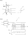
- FIG. 1 schematically shows a positive displacement pump having a pump working chamber 1 with displacer 2, wherein the volume of the working space is changed periodically by the displacement movement.
- a suction phase of the working space is connected to a suction line 3 and fills the working space with the fluid.
- the conveying medium is then transported compressed to a pressure line 4 and discharged there in an ejection phase.
- the displacer 2 then returns to its suction phase position, so that the pumping operation repeats periodically.
- intake phase and ejection phase increases the pressure in the working space, and then drop back to the initial value in the next intake phase.
- the displacer is driven by a motor 5 flanged to the working space, preferably via a drive shaft 6 connected to the displacer.
- the working volumes are generally arranged regularly around the rotating drive shaft of the engine in order to allocate the respective working volumes Displacer to operate offset. Per revolution of the drive shaft therefore occur at certain angles pressure peaks in the pressure line, which are separated by phases of decreasing pressure.
- the displacement of the working volumes by the displacers is always associated with a relative movement of parts of the pump construction. In this case, the escape of the compressed fluid must be prevented by unavoidable gaps.
- the seals used in the pumps are therefore exposed to high loads. If there is damage to the seal or sliding surfaces, the performance or efficiency of the pump will decrease due to internal leakage. However, the performance or the efficiency of the pump can also be due to various other reasons, eg. B. leaking valves or valves are caused at the inlet to the intake or at the output to the pressure line. Damage to the drive of the pump can also lead to a reduction in performance or failure of the pump. Important in the monitoring of positive displacement pumps, but also other positive displacement machines, it is therefore to be aware of an emerging failure or damage to the positive displacement machine at an early stage.
- the displacement position-dependent system pressure curve gives high-precision and detailed functional changes in positive-displacement machine operation, so that when an analysis of the displacement position-dependent system pressure curve, functional errors can be detected at an early stage and, if necessary, also eliminated.
- the detection of a displacement position-dependent system pressure curve can also be carried out with a simple and inexpensive hardware, usually with the usually existing pressure sensors for determining the system pressure or position encoders for detecting the drive shaft rotation.
- FIG. 1 shows a possible design of the device according to the invention for monitoring the positive displacement pump, wherein a pressure sensor 7 is provided on the pressure line 6. Alternatively, however, it is also possible to provide the pressure transducer directly at the outlet of the working volume of the pump.
- a position sensor 8 is in the in FIG. 1 illustrated embodiment of the positive displacement pump to the drive shaft 6 of the displacer 2 is arranged. However, it is also possible to arrange the position sensor directly on the displacer.
- the signals detected by the pressure sensor or position sensor are forwarded to a monitoring device 9. This monitoring device 9 can also be part of the pump control.
- an incremental encoder in particular a low-resolution, cost-effective incremental encoder can be used.
- the incremental encoder is coupled to a rotating structural element which is in communication with the displacer in the working volume of the positive displacement pump, e.g. B. the drive shaft or a transmission or a clutch and can detect a change in position.
- the incremental encoder has a material measure with a repetitive one periodic counting track, wherein the count value information about a distance, z. B. a relative angle within a revolution, and a direction of travel, z. B. the angle of rotation supplies.
- the ascertained count of the incremental encoder thus provides information about the relative angle within one revolution and about the angular velocity, and thus about the rotational speed of the pump.
- Incremental encoders can scan the rotating design element photoelectrically, magnetically or with sliding contacts.
- a digital sensor can also be used as position transmitter.
- the digital sensor may in turn operate photoelectrically, magnetically or with sliding contacts, wherein the digital sensor is designed to detect an element that is correlated with the periodic movement of the displacer, for. Example, a point on the drive shaft of the displacer, which passes the displacer once per revolution.
- the digital input of the digital sensor records the time of the passage with a high time resolution.
- the position input circuit 91 then has a local, high-resolution clock synchronized with the displacement machine control, which allows the formation of a time stamp. This time stamp is then correlated with the digital sensor to determine with high precision the timing of the change of the digital signal.
- the position input circuit 91 of the monitoring circuit may further include dead-time compensation to compensate for dead times in the signal detection and processing. Namely, the pump drive usually responds to a change in the pump power with a speed change. This will cause a shift in the System pressure curve simulated relative to the determined displacement position. This dead time compensation can be compensated in the positive displacement pump with the aid of the determined speed by the dead time compensation.
- the pressure transducer delivers a high number of measured values via the periodic displacement movement.
- At one pump revolution at least 100, preferably 400, values are determined.
- the system pressure values are scanned at equidistant intervals over a full cycle of the displacement movement.
- the system pressure values are preferably detected in packets by a pressure input circuit 92, which uses a locally high-resolution clock synchronized with the displacement machine control.
- the input circuit is thereby enabled not only to transmit one measurement per cycle of the controller and the subordinate communication system, but to provide a set of time equidistantly sampled system pressure values, so that a high-resolution detailed representation is possible.
- the monitoring device 9 further has a table memory 93, which is connected to the position input circuit 91 for determining the displacement position and the pressure input circuit 92 for detecting the system pressure values.
- the table memory 93 has a number of memory locations, each memory location being associated with a particular displacement position. At each actual position, the table memory then stores the associated system pressure value or the associated set of system pressure values and thus correlates the displacement positions with the system pressure values.
- K is the reciprocal of the filter constant and may be a value of 0 to 1, wherein preferably a small K value is selected.
- the filter function ensures that disturbance values only have a limited effect on the table value stored in the memory locations.
- the use of the displacer position for addressing the memory locations ensures additional filtering since all signal components which are not synchronized with the period of the displacer movement are virtually randomly distributed and averaged out to the memory locations of the table memory. Only the signal components which are synchronous with the periodic displacement movement and thus the useful components are supplied to filters associated with the memory locations. This creates a correlated filter that avoids a temporal worsening of the system pressure curve.
- FIG. 3A shows one with the help of the monitoring device according to FIG. 2 determined system pressure curve for a positive displacement pump with six working volumes and six displacers, whereby a correct pump operation with six pressure maxima and six pressure minima is shown.
- FIG. 3B shows the same pump as in FIG. 3A in the total failure of the clockwise third pressure pulse.
- the displacement position-dependent system pressure profile stored in the table memory 93 of the monitoring device 9 is evaluated in an evaluation device 94 with an expected displacement position-dependent System pressure history compared to detect malfunctions. Functional changes can be recognized immediately from the comparison carried out by the evaluation device 94 and the associated causes determined, since these lead to a characteristic deviation between the detected and expected displacement position-dependent system pressure profile. This helps to detect internal leaks, blocked controls, engine phase failure, and engine bearing damage. Also, a short circuit in the motor or an asymmetry in the mains supply can be detected. On the basis of the evaluation of the pump state carried out by the evaluation device 94, an output device 95 connected downstream of the evaluation device can then output a message or alarms.
Landscapes
- Engineering & Computer Science (AREA)
- Mechanical Engineering (AREA)
- General Engineering & Computer Science (AREA)
- Measuring Fluid Pressure (AREA)
- Control Of Positive-Displacement Pumps (AREA)
- Testing Of Engines (AREA)
Claims (11)
- Procédé, destiné à superviser une machine à déplacement positif, pourvue d'un organe déplaceur (2) modifiant périodiquement sa position dans un espace de travail (1), une pression du système étant détectée en tant que fonction d'une position de l'organe déplaceur et la courbe de pression système résultante, dépendant de la position de l'organe déplaceur étant comparée avec une courbe de pression système attendue, dépendant de la position de l'organe déplaceur pour constater des dysfonctionnements,
caractérisé en ce que les valeurs mesurées de la pression système sont filtrées et enregistrées dans une table de mémoire (93), la table de mémoire (93) comportant une série d'emplacements de mémoire, chaque emplacement de mémoire étant affecté à une certaine position de l'organe déplaceur, à chaque emplacement de mémoire étant mémorisée une valeur de pression système correspondant à la position de l'organe déplaceur, la position actuelle de l'organe déplaceur étant utilisée comme indice destiné à adresser l'emplacement de mémoire, et une mise à jour des emplacements de mémoire des tables de mémoire s'effectuant à l'aide d'une fonction de filtrage. - Procédé selon la revendication 1, caractérisé en ce que la mise à jour des emplacements de mémoire de la table de mémoires s'effectue à l'aide de la fonction de filtrage suivante :

- Procédé selon la revendication 1 ou 2, caractérisé en ce que la pression du système est détectée sur un tour plein du mouvement de déplacement dans l'espace de travail (1), comme un ensemble de valeurs de pression système, balayées à intervalles équidistants.
- Procédé selon la revendication 3, caractérisé en ce qu'une détection par paquet des valeurs de pression système est réalisée, pour chaque point de détection étant mis à disposition un ensemble de valeurs balayées à intervalles équidistants.
- Procédé selon l'une quelconque des revendications 1 à 4, caractérisé en ce qu'il s'effectue une récupération des temps morts de la position de l'organe déplaceur déterminée.
- Dispositif destiné à superviser une machine à déplacement positif, pourvu d'un capteur de position (8), destiné à détecter une position d'un organe déplaceur (2) de la machine à déplacement positif modifiant périodiquement sa position dans un espace de travail,
un capteur de pression (7), destiné à détecter une pression du système de la machine à déplacement positif,
un système de corrélation (91, 92, 93), destiné à corréler les positions de l'organe de déplacement détectées avec les valeurs de pression système détectées, pour déterminer une courbe de pression système dépendant de la position de l'organe déplaceur et
un système d'évaluation (94), destiné à comparer la courbe de pression système dépendant de la position de l'organe déplaceur avec une courbe de pression système attendue, dépendant de la position de l'organe déplaceur, pour constater des dysfonctionnements,
caractérisé en ce que le système de corrélation (91, 92, 93) comporte un filtre, pour le filtrage des valeurs de pression système détectées et une table de mémoire (93), pour mémoriser les valeurs de pression système détectées, la table de mémoire (93) comportant une série d'emplacements de mémoire, chaque emplacement de mémoire étant affecté à une certaine position de l'organe déplaceur, à chaque emplacement de mémoire étant mémorisée une valeur de pression système correspondant à la position de l'organe déplaceur, la position actuelle de l'organe déplaceur étant l'indice pour les emplacements de mémoire de la table de mémoire, pour l'adressage des emplacements de mémoire et une mise à jour des emplacements de mémoire s'effectuant à l'aide d'une fonction de filtrage du filtre. - Dispositif selon la revendication 6, caractérisé en ce que le filtre réalise la fonction de filtrage suivante :

- Dispositif selon la revendication 6 ou 7, caractérisé en ce qu'un système de compensation est prévu pour récupérer un temps mort de la position de l'organe déplaceur.
- Dispositif selon l'une quelconque des revendications 6 à 8, caractérisé en ce que le capteur de position (8) est un encodeur incrémental ou un capteur numérique.
- Dispositif selon l'une quelconque des revendications 6 à 9, caractérisé en ce que le capteur de pression (9) est conçu pour la détection par paquets de valeurs de pression système.
- Machine à déplacement positif, dotée d'un dispositif selon l'une quelconque des revendications 6 à 10.
Applications Claiming Priority (1)
| Application Number | Priority Date | Filing Date | Title |
|---|---|---|---|
| DE200810035954 DE102008035954A1 (de) | 2008-07-31 | 2008-07-31 | Verfahren und Vorrichtung zum Überwachen einer Verdrängermaschine |
Publications (3)
| Publication Number | Publication Date |
|---|---|
| EP2149706A2 EP2149706A2 (fr) | 2010-02-03 |
| EP2149706A3 EP2149706A3 (fr) | 2014-03-19 |
| EP2149706B1 true EP2149706B1 (fr) | 2018-11-21 |
Family
ID=41334616
Family Applications (1)
| Application Number | Title | Priority Date | Filing Date |
|---|---|---|---|
| EP09164562.2A Active EP2149706B1 (fr) | 2008-07-31 | 2009-07-03 | Procédé et dispositif destinés à la surveillance d'une machine à déplacement positif |
Country Status (2)
| Country | Link |
|---|---|
| EP (1) | EP2149706B1 (fr) |
| DE (1) | DE102008035954A1 (fr) |
Families Citing this family (7)
| Publication number | Priority date | Publication date | Assignee | Title |
|---|---|---|---|---|
| US8807959B2 (en) * | 2010-11-30 | 2014-08-19 | General Electric Company | Reciprocating compressor and methods for monitoring operation of same |
| DE102011115650B4 (de) * | 2011-09-28 | 2022-03-03 | Robert Bosch Gmbh | Verfahren zur Diagnose des Zustandes einer hydrostatischen Verdrängermaschine und hydraulische Anordnung mit hydrostatischer Verdrängermaschine |
| DE102015200222A1 (de) * | 2015-01-09 | 2016-07-14 | Mahle International Gmbh | Prüfvorrichtung zur Prüfung einer Pendelschieberpumpe/Flügelzellenpumpe |
| DE102018210470A1 (de) | 2018-06-27 | 2020-01-02 | Robert Bosch Gmbh | Verfahren zur Schadensfrüherkennung, sowie Programm und Steuergerät zum Ausführen des Verfahrens |
| AT521016B1 (de) | 2018-08-24 | 2019-10-15 | Engel Austria Gmbh | Verfahren und Vorrichtung zur Zustandsüberwachung einer Hydraulikpumpe |
| DE102019219633A1 (de) * | 2019-12-14 | 2021-06-17 | Robert Bosch Gmbh | Verfahren zum Kalibrieren und Betreiben einer Pumpe |
| EP4098889B1 (fr) | 2021-06-02 | 2023-09-20 | AIRBUS HELICOPTERS DEUTSCHLAND GmbH | Appareil de détection de défaillance pour un système hydraulique |
Family Cites Families (10)
| Publication number | Priority date | Publication date | Assignee | Title |
|---|---|---|---|---|
| US5332366A (en) * | 1993-01-22 | 1994-07-26 | Schwing America, Inc. | Concrete pump monitoring system |
| DE19738844A1 (de) * | 1997-09-05 | 1999-04-22 | Dosier Und Prozestechnik Salzw | Verfahren zur kontinuierlichen elektronischen Überwachung aller Funktionen innerhalb der Dosierpumpe |
| DE10108006A1 (de) * | 2001-02-20 | 2002-08-22 | Man B&W Diesel A/S, Copenhagen Sv | Verfahren zur Überwachung einer Hubkolbenmaschine sowie diesbezügliche Hubkolbenmaschine |
| US7083392B2 (en) * | 2001-11-26 | 2006-08-01 | Shurflo Pump Manufacturing Company, Inc. | Pump and pump control circuit apparatus and method |
| DE10244203A1 (de) * | 2002-09-23 | 2004-04-01 | Robert Bosch Gmbh | Verfahren und Vorrichtung zur Erfassung der Drehzahl einer Pumpe |
| KR100520071B1 (ko) * | 2003-06-11 | 2005-10-11 | 삼성전자주식회사 | 리니어 압축기 및 그 제어방법 |
| DE10334817A1 (de) | 2003-07-30 | 2005-03-10 | Bosch Rexroth Ag | Vorrichtung und Verfahren zur Fehlererkennung an Pumpen |
| GB2433792B (en) * | 2004-07-13 | 2008-09-10 | Waters Investments Ltd | High pressure pump controller |
| DE102005017240A1 (de) * | 2005-04-14 | 2006-10-19 | Alldos Eichler Gmbh | Verfahren und Vorrichtung zur Überwachung eines mittels einer Pumpe geförderten Fluidstromes |
| DE102005059564A1 (de) | 2005-12-13 | 2007-06-14 | Brueninghaus Hydromatik Gmbh | Vorrichtung und Verfahren zur Zustandsüberwachung bei hydrostatischen Verdrängereinheiten |
-
2008
- 2008-07-31 DE DE200810035954 patent/DE102008035954A1/de not_active Withdrawn
-
2009
- 2009-07-03 EP EP09164562.2A patent/EP2149706B1/fr active Active
Non-Patent Citations (1)
| Title |
|---|
| None * |
Also Published As
| Publication number | Publication date |
|---|---|
| EP2149706A3 (fr) | 2014-03-19 |
| DE102008035954A1 (de) | 2010-02-04 |
| EP2149706A2 (fr) | 2010-02-03 |
Similar Documents
| Publication | Publication Date | Title |
|---|---|---|
| EP2149706A2 (fr) | Procédé et dispositif destinés à la surveillance d'une machine à déplacement positif | |
| EP1625321B1 (fr) | Systeme et procede de diagnostic pour soupape, en particulier pour soupape de non retour d'une pompe volumetrique | |
| DE19625947C1 (de) | Verfahren zur Störungsfrüherkennung an Pumpen sowie entsprechende Vorrichtung | |
| EP3803122B1 (fr) | Procédé pour déterminer ou surveiller l'état d'une pompe à vis excentrique | |
| EP2549257B1 (fr) | Procédé de détection de dommages sur des engrenages | |
| EP2047118B1 (fr) | Procédé de localisation de défaut et de diagnostic d'une installation fluidique | |
| WO2006131435A1 (fr) | Procede et dispositif pour corriger un signal d'un capteur | |
| AT521016B1 (de) | Verfahren und Vorrichtung zur Zustandsüberwachung einer Hydraulikpumpe | |
| EP3019845A1 (fr) | Procédé et système de surveillance d'un équipement technique tel qu'une machine ou une installation | |
| DE19545008A1 (de) | Verfahren und Vorrichtung zur Überwachung von Maschinen | |
| EP2587225A1 (fr) | Procédé de détermination d'un angle de rotation | |
| EP2291617A1 (fr) | Système de surveillance d'un organe soumis à des vibrations | |
| WO2008012070A2 (fr) | Procédé et dispositif d'analyse des vibrations d'une machine | |
| CN1413302A (zh) | 识别在一个信号传感器上极性改变的方法和装置 | |
| DE102005059564A1 (de) | Vorrichtung und Verfahren zur Zustandsüberwachung bei hydrostatischen Verdrängereinheiten | |
| EP2881584B1 (fr) | Détection de pannes sans capteur pour des pompes de dosage dotées d'un moteur pas à pas | |
| DE2537219A1 (de) | Verfahren zum kontrollieren der winkelrichtigen einstellung von periodischen einspritzvorgaengen | |
| DE102005019515C5 (de) | Verfahren zum Messen der Drehzahl eines EC-Motors | |
| DE102005059566B4 (de) | Vorrichtung und Verfahren zur zustandsabhängigen Wartung von hydrostatischen Verdrängereinheiten | |
| DE102010033344A1 (de) | Verfahren zur Überwachung von Antriebskomponenten eines Großhydraulikbaggers | |
| EP1747380B1 (fr) | Procede de localisation de defaut et diagnostic d'une installation fluidique | |
| DE102006053483B4 (de) | Verfahren zur Überwachung einer Klopfregelung und Vorrichtung zur Klopfregelung einer Brennkraftmaschine | |
| DE3912277A1 (de) | Hydromaschine | |
| DE102014225867A1 (de) | Vorrichtung und Verfahren zur Überprüfung eines Arbeitstaktsignals einer Positionsmesseinrichtung | |
| EP2469239B1 (fr) | Dispositif de mesure d'angle multi-tours |
Legal Events
| Date | Code | Title | Description |
|---|---|---|---|
| PUAI | Public reference made under article 153(3) epc to a published international application that has entered the european phase |
Free format text: ORIGINAL CODE: 0009012 |
|
| AK | Designated contracting states |
Kind code of ref document: A2 Designated state(s): AT BE BG CH CY CZ DE DK EE ES FI FR GB GR HR HU IE IS IT LI LT LU LV MC MK MT NL NO PL PT RO SE SI SK SM TR |
|
| AX | Request for extension of the european patent |
Extension state: AL BA RS |
|
| PUAL | Search report despatched |
Free format text: ORIGINAL CODE: 0009013 |
|
| AK | Designated contracting states |
Kind code of ref document: A3 Designated state(s): AT BE BG CH CY CZ DE DK EE ES FI FR GB GR HR HU IE IS IT LI LT LU LV MC MK MT NL NO PL PT RO SE SI SK SM TR |
|
| AX | Request for extension of the european patent |
Extension state: AL BA RS |
|
| RIC1 | Information provided on ipc code assigned before grant |
Ipc: F04B 51/00 20060101AFI20140207BHEP |
|
| 17P | Request for examination filed |
Effective date: 20140918 |
|
| RBV | Designated contracting states (corrected) |
Designated state(s): AT BE BG CH CY CZ DE DK EE ES FI FR GB GR HR HU IE IS IT LI LT LU LV MC MK MT NL NO PL PT RO SE SI SK SM TR |
|
| 17Q | First examination report despatched |
Effective date: 20160805 |
|
| STAA | Information on the status of an ep patent application or granted ep patent |
Free format text: STATUS: EXAMINATION IS IN PROGRESS |
|
| GRAP | Despatch of communication of intention to grant a patent |
Free format text: ORIGINAL CODE: EPIDOSNIGR1 |
|
| STAA | Information on the status of an ep patent application or granted ep patent |
Free format text: STATUS: GRANT OF PATENT IS INTENDED |
|
| INTG | Intention to grant announced |
Effective date: 20180621 |
|
| GRAS | Grant fee paid |
Free format text: ORIGINAL CODE: EPIDOSNIGR3 |
|
| GRAA | (expected) grant |
Free format text: ORIGINAL CODE: 0009210 |
|
| STAA | Information on the status of an ep patent application or granted ep patent |
Free format text: STATUS: THE PATENT HAS BEEN GRANTED |
|
| AK | Designated contracting states |
Kind code of ref document: B1 Designated state(s): AT BE BG CH CY CZ DE DK EE ES FI FR GB GR HR HU IE IS IT LI LT LU LV MC MK MT NL NO PL PT RO SE SI SK SM TR |
|
| REG | Reference to a national code |
Ref country code: CH Ref legal event code: EP |
|
| REG | Reference to a national code |
Ref country code: IE Ref legal event code: FG4D Free format text: LANGUAGE OF EP DOCUMENT: GERMAN |
|
| REG | Reference to a national code |
Ref country code: AT Ref legal event code: REF Ref document number: 1067856 Country of ref document: AT Kind code of ref document: T Effective date: 20181215 |
|
| REG | Reference to a national code |
Ref country code: DE Ref legal event code: R096 Ref document number: 502009015465 Country of ref document: DE |
|
| REG | Reference to a national code |
Ref country code: NL Ref legal event code: MP Effective date: 20181121 |
|
| PG25 | Lapsed in a contracting state [announced via postgrant information from national office to epo] |
Ref country code: LT Free format text: LAPSE BECAUSE OF FAILURE TO SUBMIT A TRANSLATION OF THE DESCRIPTION OR TO PAY THE FEE WITHIN THE PRESCRIBED TIME-LIMIT Effective date: 20181121 Ref country code: NO Free format text: LAPSE BECAUSE OF FAILURE TO SUBMIT A TRANSLATION OF THE DESCRIPTION OR TO PAY THE FEE WITHIN THE PRESCRIBED TIME-LIMIT Effective date: 20190221 Ref country code: HR Free format text: LAPSE BECAUSE OF FAILURE TO SUBMIT A TRANSLATION OF THE DESCRIPTION OR TO PAY THE FEE WITHIN THE PRESCRIBED TIME-LIMIT Effective date: 20181121 Ref country code: LV Free format text: LAPSE BECAUSE OF FAILURE TO SUBMIT A TRANSLATION OF THE DESCRIPTION OR TO PAY THE FEE WITHIN THE PRESCRIBED TIME-LIMIT Effective date: 20181121 Ref country code: IS Free format text: LAPSE BECAUSE OF FAILURE TO SUBMIT A TRANSLATION OF THE DESCRIPTION OR TO PAY THE FEE WITHIN THE PRESCRIBED TIME-LIMIT Effective date: 20190321 Ref country code: BG Free format text: LAPSE BECAUSE OF FAILURE TO SUBMIT A TRANSLATION OF THE DESCRIPTION OR TO PAY THE FEE WITHIN THE PRESCRIBED TIME-LIMIT Effective date: 20190221 Ref country code: ES Free format text: LAPSE BECAUSE OF FAILURE TO SUBMIT A TRANSLATION OF THE DESCRIPTION OR TO PAY THE FEE WITHIN THE PRESCRIBED TIME-LIMIT Effective date: 20181121 Ref country code: FI Free format text: LAPSE BECAUSE OF FAILURE TO SUBMIT A TRANSLATION OF THE DESCRIPTION OR TO PAY THE FEE WITHIN THE PRESCRIBED TIME-LIMIT Effective date: 20181121 |
|
| PG25 | Lapsed in a contracting state [announced via postgrant information from national office to epo] |
Ref country code: GR Free format text: LAPSE BECAUSE OF FAILURE TO SUBMIT A TRANSLATION OF THE DESCRIPTION OR TO PAY THE FEE WITHIN THE PRESCRIBED TIME-LIMIT Effective date: 20190222 Ref country code: SE Free format text: LAPSE BECAUSE OF FAILURE TO SUBMIT A TRANSLATION OF THE DESCRIPTION OR TO PAY THE FEE WITHIN THE PRESCRIBED TIME-LIMIT Effective date: 20181121 Ref country code: PT Free format text: LAPSE BECAUSE OF FAILURE TO SUBMIT A TRANSLATION OF THE DESCRIPTION OR TO PAY THE FEE WITHIN THE PRESCRIBED TIME-LIMIT Effective date: 20190321 Ref country code: NL Free format text: LAPSE BECAUSE OF FAILURE TO SUBMIT A TRANSLATION OF THE DESCRIPTION OR TO PAY THE FEE WITHIN THE PRESCRIBED TIME-LIMIT Effective date: 20181121 |
|
| PG25 | Lapsed in a contracting state [announced via postgrant information from national office to epo] |
Ref country code: PL Free format text: LAPSE BECAUSE OF FAILURE TO SUBMIT A TRANSLATION OF THE DESCRIPTION OR TO PAY THE FEE WITHIN THE PRESCRIBED TIME-LIMIT Effective date: 20181121 Ref country code: DK Free format text: LAPSE BECAUSE OF FAILURE TO SUBMIT A TRANSLATION OF THE DESCRIPTION OR TO PAY THE FEE WITHIN THE PRESCRIBED TIME-LIMIT Effective date: 20181121 Ref country code: CZ Free format text: LAPSE BECAUSE OF FAILURE TO SUBMIT A TRANSLATION OF THE DESCRIPTION OR TO PAY THE FEE WITHIN THE PRESCRIBED TIME-LIMIT Effective date: 20181121 |
|
| REG | Reference to a national code |
Ref country code: DE Ref legal event code: R097 Ref document number: 502009015465 Country of ref document: DE |
|
| PG25 | Lapsed in a contracting state [announced via postgrant information from national office to epo] |
Ref country code: RO Free format text: LAPSE BECAUSE OF FAILURE TO SUBMIT A TRANSLATION OF THE DESCRIPTION OR TO PAY THE FEE WITHIN THE PRESCRIBED TIME-LIMIT Effective date: 20181121 Ref country code: SM Free format text: LAPSE BECAUSE OF FAILURE TO SUBMIT A TRANSLATION OF THE DESCRIPTION OR TO PAY THE FEE WITHIN THE PRESCRIBED TIME-LIMIT Effective date: 20181121 Ref country code: EE Free format text: LAPSE BECAUSE OF FAILURE TO SUBMIT A TRANSLATION OF THE DESCRIPTION OR TO PAY THE FEE WITHIN THE PRESCRIBED TIME-LIMIT Effective date: 20181121 Ref country code: SK Free format text: LAPSE BECAUSE OF FAILURE TO SUBMIT A TRANSLATION OF THE DESCRIPTION OR TO PAY THE FEE WITHIN THE PRESCRIBED TIME-LIMIT Effective date: 20181121 |
|
| PLBE | No opposition filed within time limit |
Free format text: ORIGINAL CODE: 0009261 |
|
| STAA | Information on the status of an ep patent application or granted ep patent |
Free format text: STATUS: NO OPPOSITION FILED WITHIN TIME LIMIT |
|
| 26N | No opposition filed |
Effective date: 20190822 |
|
| PG25 | Lapsed in a contracting state [announced via postgrant information from national office to epo] |
Ref country code: SI Free format text: LAPSE BECAUSE OF FAILURE TO SUBMIT A TRANSLATION OF THE DESCRIPTION OR TO PAY THE FEE WITHIN THE PRESCRIBED TIME-LIMIT Effective date: 20181121 |
|
| PG25 | Lapsed in a contracting state [announced via postgrant information from national office to epo] |
Ref country code: MC Free format text: LAPSE BECAUSE OF FAILURE TO SUBMIT A TRANSLATION OF THE DESCRIPTION OR TO PAY THE FEE WITHIN THE PRESCRIBED TIME-LIMIT Effective date: 20181121 |
|
| GBPC | Gb: european patent ceased through non-payment of renewal fee |
Effective date: 20190703 |
|
| PG25 | Lapsed in a contracting state [announced via postgrant information from national office to epo] |
Ref country code: TR Free format text: LAPSE BECAUSE OF FAILURE TO SUBMIT A TRANSLATION OF THE DESCRIPTION OR TO PAY THE FEE WITHIN THE PRESCRIBED TIME-LIMIT Effective date: 20181121 |
|
| REG | Reference to a national code |
Ref country code: BE Ref legal event code: MM Effective date: 20190731 |
|
| PG25 | Lapsed in a contracting state [announced via postgrant information from national office to epo] |
Ref country code: GB Free format text: LAPSE BECAUSE OF NON-PAYMENT OF DUE FEES Effective date: 20190703 |
|
| PG25 | Lapsed in a contracting state [announced via postgrant information from national office to epo] |
Ref country code: LU Free format text: LAPSE BECAUSE OF NON-PAYMENT OF DUE FEES Effective date: 20190703 Ref country code: BE Free format text: LAPSE BECAUSE OF NON-PAYMENT OF DUE FEES Effective date: 20190731 |
|
| PG25 | Lapsed in a contracting state [announced via postgrant information from national office to epo] |
Ref country code: IE Free format text: LAPSE BECAUSE OF NON-PAYMENT OF DUE FEES Effective date: 20190703 |
|
| PG25 | Lapsed in a contracting state [announced via postgrant information from national office to epo] |
Ref country code: CY Free format text: LAPSE BECAUSE OF FAILURE TO SUBMIT A TRANSLATION OF THE DESCRIPTION OR TO PAY THE FEE WITHIN THE PRESCRIBED TIME-LIMIT Effective date: 20181121 |
|
| PG25 | Lapsed in a contracting state [announced via postgrant information from national office to epo] |
Ref country code: MT Free format text: LAPSE BECAUSE OF FAILURE TO SUBMIT A TRANSLATION OF THE DESCRIPTION OR TO PAY THE FEE WITHIN THE PRESCRIBED TIME-LIMIT Effective date: 20181121 Ref country code: HU Free format text: LAPSE BECAUSE OF FAILURE TO SUBMIT A TRANSLATION OF THE DESCRIPTION OR TO PAY THE FEE WITHIN THE PRESCRIBED TIME-LIMIT; INVALID AB INITIO Effective date: 20090703 |
|
| PG25 | Lapsed in a contracting state [announced via postgrant information from national office to epo] |
Ref country code: MK Free format text: LAPSE BECAUSE OF FAILURE TO SUBMIT A TRANSLATION OF THE DESCRIPTION OR TO PAY THE FEE WITHIN THE PRESCRIBED TIME-LIMIT Effective date: 20181121 |
|
| PGFP | Annual fee paid to national office [announced via postgrant information from national office to epo] |
Ref country code: FR Payment date: 20240717 Year of fee payment: 16 |
|
| PGFP | Annual fee paid to national office [announced via postgrant information from national office to epo] |
Ref country code: CH Payment date: 20240801 Year of fee payment: 16 |
|
| PGFP | Annual fee paid to national office [announced via postgrant information from national office to epo] |
Ref country code: AT Payment date: 20240718 Year of fee payment: 16 |
|
| PGFP | Annual fee paid to national office [announced via postgrant information from national office to epo] |
Ref country code: IT Payment date: 20240731 Year of fee payment: 16 |
|
| PGFP | Annual fee paid to national office [announced via postgrant information from national office to epo] |
Ref country code: DE Payment date: 20250704 Year of fee payment: 17 |
|
| REG | Reference to a national code |
Ref country code: CH Ref legal event code: H13 Free format text: ST27 STATUS EVENT CODE: U-0-0-H10-H13 (AS PROVIDED BY THE NATIONAL OFFICE) Effective date: 20260224 |
|
| REG | Reference to a national code |
Ref country code: AT Ref legal event code: MM01 Ref document number: 1067856 Country of ref document: AT Kind code of ref document: T Effective date: 20250703 |
|
| PG25 | Lapsed in a contracting state [announced via postgrant information from national office to epo] |
Ref country code: AT Free format text: LAPSE BECAUSE OF NON-PAYMENT OF DUE FEES Effective date: 20250703 |
|
| PG25 | Lapsed in a contracting state [announced via postgrant information from national office to epo] |
Ref country code: FR Free format text: LAPSE BECAUSE OF NON-PAYMENT OF DUE FEES Effective date: 20250731 |
|
| PG25 | Lapsed in a contracting state [announced via postgrant information from national office to epo] |
Ref country code: CH Free format text: LAPSE BECAUSE OF NON-PAYMENT OF DUE FEES Effective date: 20250731 |