EP2149753A2 - Four à combustible solide - Google Patents
Four à combustible solide Download PDFInfo
- Publication number
- EP2149753A2 EP2149753A2 EP09401014A EP09401014A EP2149753A2 EP 2149753 A2 EP2149753 A2 EP 2149753A2 EP 09401014 A EP09401014 A EP 09401014A EP 09401014 A EP09401014 A EP 09401014A EP 2149753 A2 EP2149753 A2 EP 2149753A2
- Authority
- EP
- European Patent Office
- Prior art keywords
- solid fuel
- combustion chamber
- stove
- module
- range according
- Prior art date
- Legal status (The legal status is an assumption and is not a legal conclusion. Google has not performed a legal analysis and makes no representation as to the accuracy of the status listed.)
- Withdrawn
Links
Images

Classifications
-
- F—MECHANICAL ENGINEERING; LIGHTING; HEATING; WEAPONS; BLASTING
- F24—HEATING; RANGES; VENTILATING
- F24B—DOMESTIC STOVES OR RANGES FOR SOLID FUELS; IMPLEMENTS FOR USE IN CONNECTION WITH STOVES OR RANGES
- F24B1/00—Stoves or ranges
- F24B1/20—Ranges
-
- F—MECHANICAL ENGINEERING; LIGHTING; HEATING; WEAPONS; BLASTING
- F24—HEATING; RANGES; VENTILATING
- F24B—DOMESTIC STOVES OR RANGES FOR SOLID FUELS; IMPLEMENTS FOR USE IN CONNECTION WITH STOVES OR RANGES
- F24B5/00—Combustion-air or flue-gas circulation in or around stoves or ranges
- F24B5/02—Combustion-air or flue-gas circulation in or around stoves or ranges in or around stoves
- F24B5/021—Combustion-air or flue-gas circulation in or around stoves or ranges in or around stoves combustion-air circulation
- F24B5/023—Supply of primary air for combustion
Definitions
- the invention relates to a solid fuel stove with supply air, a combustion chamber, at least one SchuK Kom and a stove top.
- Such solid fuel stoves are known in various configurations in the prior art. For example, is from the DE 195 05 187 A1 a solid fuel stove with Zu Kunststoff Unit, combustion chamber and Ausbrandzone known as Schugaszug having a loosely placed hotplate, which comes into direct contact with the combustion gases. This solid fuel stove has next to the combustion chamber on a baking tube box and a water vessel.
- the disadvantage is that the known solid fuel stoves are not smoke-gas-tight, that is, they are not room air-independent.
- a room air-independent supply air duct with flue gas-tight combustion chamber has been proposed for stoves.
- the supply air is supplied independent of ambient air via a tight pipeline under normal atmospheric pressure from the outside air.
- the combustion chamber is formed smoke-tight and the Combustion gases are also directed smoke-tight into the chimney, from where they pass through the train created in the chimney.
- the known solid fuel stoves can not guarantee the required tightness, since the loosely inserted stovetop, which is usually even slotted, due to the temperature differences occurring during operation and related significant expansions gas exchange between the combustion chamber and living space permits.
- combustion gases can also escape through settlement or expansion cracks, which also arise due to temperature fluctuations, due to the slight negative pressure in the living room in the living room. There is thus a significant risk of poisoning for the residents in such a constellation.
- the object of the invention is to provide a solid fuel stove that can be used in buildings in conjunction with ventilation systems.
- a solid fuel stove according to claim 1.
- the combustion air is supplied to the stove independently of room air via a sealed pipe under normal atmospheric pressure. Furthermore, the combustion chamber and the flue gas draft smoke-tight created, so that flue gases can not escape even in vacuum in the living room here.
- the stove plate is arranged in heat-conducting contact on the combustion chamber and / or the Schugaszug.
- the stove plate itself does not need to be sealed separately, since the component underneath, namely the combustion chamber and / or the hot gas flue are designed to be smoke gas tight.
- conventional stovetops with thermal expansion slots, hearth ring hole and the like can advantageously be used.
- other suitable materials for the stove top such as glass ceramic surfaces, may be used.
- a sealing of the stove plate in the rest of the body of solid fuel stove is not required and due to the considerable thermal stress and concomitant strains also not desirable.
- a heat-conductive mat especially stainless steel wool, inserted.
- the mat made of preferably stainless steel wool serves as an expansion buffer and allows rapid heat transfer.
- the combustion chamber has a combustion chamber door with a smoke-tight closing device.
- the closing device ensures that the firebox door closes automatically, for example, acted upon by spring force.
- an open firebox door is avoided, because with open firebox door would be able to pull into the living space due to the low negative pressure in the living room flue gases.
- a baking compartment which is surrounded by flue gas-tight heating gas ducts
- the baking compartment itself and thus also the baking-chamber flap can be designed without special seals and provisions for shielding flue gases. Only the heating gas channels that surround the baking chamber are permanently formed smoke-tight.
- the solid fuel stove is constructed modularly, namely a supply air module for the supply air, a combustion chamber for the combustion chamber and at least one train module for Schugaszug contains and the modules transitions to Supply air and have to Schugas Entry, which are connected smoke-tight with each other.
- different, possibly standardized modules can be combined with each other, whereby an adapted to the conditions, individual stove can be created.
- the standardized modules can be mass-produced cost-effectively in industrial quantities. With the modules, a building system is created as it were, in which a logical separation of the different functions of the solid fuel stove is taken into account.
- the supply air module receives a tight connection to an air supply pipe, which can attract air at atmospheric pressure from the outside environment outside the building.
- the combustion chamber module is connected to the supply air module and contains a combustion chamber door for supplying the fuel, for example wood.
- the tensile module which may also be designed in several parts, is attached to the combustion chamber module and directs the combustion gases to the chimney, which is also connected smoke-tight to the last flowed through train module.
- the entire air or heating gas duct can be made tight by simple means during on-site installation.
- Flanges with sealing surfaces are preferably provided at the junctions for screw-gas-tight screwing.
- the transition flanges are tapered with respect to the module dimensions, wherein the transitions however, have a sufficient cross section for the flue gas duct. Due to the tapered design of the flange, the sealing surface dimension is reduced so much that manufacturing tolerances and uneven stresses are easily absorbed by the flanges.
- the provision of flange connections when assembling the modules at the site the required tightness at the transitions can be ensured without complex connections, such as by welding must be made on site.
- an optional transition is provided on the combustion chamber module and / or on the train module to which a supplementary module with the baking compartment, a warming compartment and / or a water vessel can be connected, an expansion option for the stove is provided, the baking compartment, a warming compartment or a water ship or any combination thereof.
- the optional transition on the combustion chamber module or on the tensile module is sealed with a lid in a smoke-tight manner, if this optional transition is not required. If the stove, for example, contain a baking chamber, a supplementary module with the baking chamber is connected after removal of the lid at the optional transition smoke gas tight.
- the supply air module is preferably arranged below and a first tensile module is arranged above the combustion chamber module.
- a first tensile module is arranged above the combustion chamber module.
- outside air is passed with sealing connection in the supply air module and fed from there to the combustion chamber in the combustion chamber module.
- the rising in the combustion chamber combustion gases are inevitably directed into the overlying first train module.
- partitions are preferably arranged for the angular guidance of the hot gases.
- the connection of the stove to the chimney can be made very flexible.
- To the flue gas guide unaffected by the selected connection piece for the Can also be provided behind the train module flue gas duct, from which the four connecting piece depart.
- modules are made of metal, precious metal or alloys thereof, preferably of sheet metal by means of edges and welding, the permanent smoke gas tightness can be achieved particularly easily.
- modules made of stainless steel sheets are preferred.
- the modules can be industrially produced in large series.
- the stove plate consists of a ground steel or stainless steel plate, preferably with a thickness of 6 to 15 mm, of a natural stone plate or of a glass or ceramic plate or combinations thereof and is framed with a frame, preferably of ground stainless steel.
- a frame preferably of ground stainless steel.
- a solid fuel stove consisting of the gas-tight composite construction system can be provided with a highly effective heat storage layer to the heat of combustion from the combustion chamber slowly and distributed for to give off the heating of the living space, in particular via radiant heat (basic furnace effect).
- modules of a, preferably masonry, outer cladding made of metal, for example, powder-coated, enamelled or stove enamelled, be wrapped from stove tiles, soapstone and / or fireclay plates.
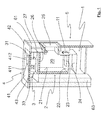
- a solid fuel range is shown in a cutaway spatial view.
- the solid fuel stove has a supply air module 1, a combustion chamber module 2 and a tensile module 3.
- the supply air module 1 has a connecting piece, not shown, to which a pipe for supplying external air is sealingly connected.
- combustion air ducts 11 are provided which supply the combustion air to a combustion chamber 20 in a combustion chamber 2.
- the combustion chamber module 2 has a combustion chamber 20, which is lined with a combustion chamber lining 21, preferably made of fireclay. On the combustion chamber floor 22 a loosely inserted grate 23 is arranged with an ash collecting container 24 arranged underneath.
- a combustion chamber door 25 is attached in various embodiments on the front side of the combustion chamber module 2 smoke-tight, for example via a flange connection.
- the furnace door 25 has a door closing device with an automatic lock according to DE 101 01 246 C1 on, whereby a permanently smoke-gas-tight combustion chamber door is guaranteed even with greater differential pressure between the living room and the combustion chamber.
- a burn-through 27 in the form of a smoke gas-tight transition to the tensile modulus 3 is provided in the combustion chamber ceiling 26, a burn-through 27 in the form of a smoke gas-tight transition to the tensile modulus 3 is provided.
- a connection 31 for the admission of the combustion gases into the tensile modulus 3 is provided in a matching position for burnout 27 of the combustion chamber module 2.
- the port 31 is screwed or welded smoke-tight with the transition / burnout 27 of the combustion chamber module.
- a lying Edelgaszug 32 is arranged, which forms by means of baffles a long, angled throttle cable.
- a flue gas channel 33 is arranged transversely across the rear end across the width of the hearth.
- four connecting pieces 34 are provided for the flue gas outlet in the chimney. These lie on the flue gas duct 33 rear left, rear right and on the left side as well as on the right side of the flue gas duct 33.
- the stove top 4 consists of a stove plate 41, which is equipped, for example, as a ground steel plate with expansion slots 411 and hearth ring hole 412, and a frame 42, which surrounds the stove plate 41.
- the hearth frame 42 may be made of ground stainless steel, for example.
- the stove plate 41 and the frame 42 are preferably aligned plane and form the stove top 4.
- the stove plate 41 is inserted only in the frame 42 and is in the illustrated embodiment above the tension module 3, wherein between train module 3 and hotplate 41, a heat-conducting mat 43 made of stainless steel wool is inserted.
- the stainless steel wool compensates thermally induced movements and allows rapid heat transfer from the tensile modulus 3 to the hearth 41.
- the modules mounted one above the other namely supply air module 1, combustion chamber module 2 and tensile module 3, are laterally encased by an outer covering 6.
- the outer lining 6 consists of ceramic stove tiles 61, which are fixed to the construction system formed from the modules 1, 2, 3, for example, are mounted. These oven tiles 61 form the visible outer lining 6 of the solid fuel stove. Due to the heat radiation from the combustion chamber module 2 and the tensile modulus 3, the furnace tiles 61 act as heat radiation emitting heating surfaces. If desired, the solid fuel stove can also perform a convection heating function. For a recirculation opening 62 is provided in the front near the bottom. Accordingly, a hot air discharge opening must be placed at the top of the stove. This is not shown separately in the accompanying figures. In this embodiment, then forms a thermally induced air flow, which flows around the building system of supply air module, combustion chamber module and train module, but within the outer panel 6 and absorbs heat, as is known from conventional tiled stoves.
- the outer lining 6 is formed as a thermal barrier coating 63. With the thermal barrier coating 63, excessive heating of the adjacent wall is avoided.
- the outer lining 6 can be provided as a heat storage layer or between the outer lining 6 and the module structure, a heat storage layer, which is not shown here in the figures.
- the heat storage layer is preferably made of firebricks or soapstone.
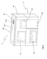
- Fig. 2 is a solid fuel stove with additional baking function shown in a three-dimensional view. Functionally identical components are designated by the same reference numerals as the first embodiment.
- the solid fuel stove according to this second embodiment corresponds in structure in terms of in Fig. 2 Right part shown in the first embodiment.
- the construction system according to the first exemplary embodiment with incoming air module 1, combustion chamber module 2 and tensile module 3 is a supplementary module 5, as shown in FIG Fig. 3 illustrated inner life of the solid fuel stove with baking compartment according to the second embodiment can be seen, supplemented.
- a flange 35 is arranged on the tension module 3 on the left side. This flange 35 may in principle be provided on the tension module 3 and closed smoke-tight when not in use with a lid. If, as in the illustrated embodiment according to Fig. 2 and 3 , a supplementary module 5 is to be connected thereto, the cover is removed on the flange 35 and the flange 35, a flange 51 of the supplementary module 5 connected smoke-tight.
- the supplementary module 5 has a baking compartment, which is up to the front of the stove, as in Fig. 2 shown, enough.
- the baking compartment 52 has an openable flap in front, in order to insert or remove the baked goods.
- a gas-tight heating gas duct 53 Surrounding the baking compartment 52 is a gas-tight heating gas duct 53, which envelops the entire baking compartment.
- a flap or a shift register is preferably provided, with which optionally the flue gas path via the heating gas channel 53, the baking compartment 5 can be released around flowing.
- the oven can be activated or deactivated by adjusting the register or the flap during operation of the cooker.
- a thermally conductive mat 54 is arranged between the baking compartment 52 and the heating gas channel 53.
- a warming compartment 55 is provided below the supplementary module 5, for keeping food and drinks warm or for preheating crockery or for drying wood.
- the warming compartment 55 also has an openable flap on the front of the cooker, as shown Fig. 2 can be seen on.
- the connecting pieces 34 for connecting the stove to the chimney draft shown.
- the four connecting pieces 34 are located on the rear of the hearth transverse flue gas channel 33.
- the flue gas channel 33 extends over the entire width of the stove-back combination.
- the connecting pieces 34 are located on the right or left side of the hearth at the respective end face of the flue gas duct 33 and right and left rear at the ends of the flue gas duct 33. This ensures that the solid fuel stove as freely as possible in relation to the connected flue gas outlet to the chimney in each kitchen can be arranged.
- the stove top 4 is equipped with a frame 42 enclosed hearth 41 which extends over the entire width of the stove-oven combination.
- a frame 42 enclosed hearth 41 which extends over the entire width of the stove-oven combination.
- high cooking temperatures are achieved only immediately above the burn-through 27, ie in the right area of the hot plate 41.
- the different heat zones on the stove plate 41 can be used individually for the preparation and / or keeping food warm.
- the solid fuel stove according to the invention with its flange 35 accommodate different supplementary modules.
- modules for hot water for example as a so-called.
- Water ship or in the form of a continuous heater for domestic water heating or as a replacement or support for the central heating can be used.
- the stove can fulfill the function of a base furnace by further train modules and design with heat storage layers.
Landscapes
- Engineering & Computer Science (AREA)
- Chemical & Material Sciences (AREA)
- Combustion & Propulsion (AREA)
- Mechanical Engineering (AREA)
- General Engineering & Computer Science (AREA)
- Solid-Fuel Combustion (AREA)
Applications Claiming Priority (1)
| Application Number | Priority Date | Filing Date | Title |
|---|---|---|---|
| DE200820008804 DE202008008804U1 (de) | 2008-07-28 | 2008-07-28 | Festbrennstoffherd |
Publications (2)
| Publication Number | Publication Date |
|---|---|
| EP2149753A2 true EP2149753A2 (fr) | 2010-02-03 |
| EP2149753A3 EP2149753A3 (fr) | 2012-02-22 |
Family
ID=39829830
Family Applications (1)
| Application Number | Title | Priority Date | Filing Date |
|---|---|---|---|
| EP09401014A Withdrawn EP2149753A3 (fr) | 2008-07-28 | 2009-07-13 | Four à combustible solide |
Country Status (2)
| Country | Link |
|---|---|
| EP (1) | EP2149753A3 (fr) |
| DE (1) | DE202008008804U1 (fr) |
Families Citing this family (2)
| Publication number | Priority date | Publication date | Assignee | Title |
|---|---|---|---|---|
| DE102008059789A1 (de) * | 2008-12-01 | 2010-06-02 | Wamsler Haus- und Küchentechnik GmbH | Kochfeld zum Anordnen über einem Wärmeerzeuger |
| AT12674U1 (de) * | 2011-03-02 | 2012-09-15 | Lohberger Heiz & Kochgeraete Technologie Gmbh | Festbrennstoffherd |
Family Cites Families (9)
| Publication number | Priority date | Publication date | Assignee | Title |
|---|---|---|---|---|
| US4184473A (en) * | 1978-02-23 | 1980-01-22 | Mcintire John E | Improved mobile home heater |
| US4368721A (en) * | 1980-02-28 | 1983-01-18 | Kroupa Eugene A | Woodburning stove |
| US4359040A (en) * | 1980-07-01 | 1982-11-16 | Martenson Donald S | Free standing stove |
| DE3500186A1 (de) * | 1984-01-17 | 1985-07-18 | Alfred 8311 Unterhausbach Pollner | Waermespeicher fuer kacheloefen |
| DE19505187A1 (de) | 1995-02-16 | 1996-08-22 | Lohberger Heiz & Kochgeraete G | Festbrennstoffherd, insbesondere Kochherd und/oder Kochheizherd |
| SE520384C2 (sv) | 2000-06-09 | 2003-07-01 | Nordisk Miljoeenergi I Norr Ab | Värmekamin bestående av moduler |
| DE10101246C1 (de) | 2001-01-12 | 2002-07-11 | Deckert Maschb Gmbh | Feuerraumtürschließeinrichtung |
| DE10258888B4 (de) | 2002-12-17 | 2004-11-04 | Mertens-Kachelöfen und Fliesen GmbH | Aufbausystem für einen Grundofen sowie Grundofen |
| DE202008004705U1 (de) * | 2008-04-05 | 2008-07-17 | Martens, Jakob | Kombi-Kamin |
-
2008
- 2008-07-28 DE DE200820008804 patent/DE202008008804U1/de not_active Expired - Lifetime
-
2009
- 2009-07-13 EP EP09401014A patent/EP2149753A3/fr not_active Withdrawn
Also Published As
| Publication number | Publication date |
|---|---|
| EP2149753A3 (fr) | 2012-02-22 |
| DE202008008804U1 (de) | 2008-10-09 |
Similar Documents
| Publication | Publication Date | Title |
|---|---|---|
| DE60313486T2 (de) | Heizung mit hohem wirkungsgrad | |
| DE202010008890U1 (de) | Brennstoffeinsatz für die Benutzung in Kamin- und Kachelöfen, Heizkaminen, Kamineinsätzen und Feuerkassetten | |
| EP3051207A1 (fr) | Poêle à bois, destiné notamment à être utilisé en cuisine | |
| EP2149753A2 (fr) | Four à combustible solide | |
| DE10256585B3 (de) | Holzbackofen | |
| EP1431666B1 (fr) | Poêle reposant sur le sol avec système de montage | |
| DE202008000034U1 (de) | Heizkessel für Bio-Festbrennstoffe | |
| DE102008011167A1 (de) | Heizofen zum Beheizen des Raumes eines Wohn-Gebäudes | |
| EP1890092A1 (fr) | Feu pour le chauffage d'une enceinte et des enceintes distantes et pour le chauffage d'eau sanitaire | |
| DE102004011017B4 (de) | Grundofen | |
| DE3500157A1 (de) | Kachelofeneinsatz mit rauchgasregister | |
| DE23874C (de) | Neuerungen an Oefen mit Füllschachtfeuerungen | |
| DE102008007819B4 (de) | Montagefähiger Wärmespeicherofen | |
| DE20320384U1 (de) | Aufbausystem für einen Grundofen sowie Grundofen | |
| DE2948008A1 (de) | Feuerungseinsatz fuer kamine | |
| DE2919471A1 (de) | Offener kamin | |
| DE638614C (de) | Mit einem Brateinsatz versehener Kuechenherd | |
| DE908526C (de) | Kochherd mit eingebautem, doppelwandigem Heizkessel | |
| DE814645C (de) | Heizofen, insbesondere fuer Haushaltszwecke | |
| EP3086035B1 (fr) | Petite installation de combustion | |
| DE4316337B4 (de) | Ofen für feste Brennstoffe | |
| CH632079A5 (en) | Heating device | |
| DE8703287U1 (de) | Regelherd | |
| DE3205978A1 (de) | Heizungsanlage | |
| DE2930770A1 (de) | Zusatzheizvorrichtung fuer einen aufgestellten offenen kamin |
Legal Events
| Date | Code | Title | Description |
|---|---|---|---|
| PUAI | Public reference made under article 153(3) epc to a published international application that has entered the european phase |
Free format text: ORIGINAL CODE: 0009012 |
|
| AK | Designated contracting states |
Kind code of ref document: A2 Designated state(s): AT BE BG CH CY CZ DE DK EE ES FI FR GB GR HR HU IE IS IT LI LT LU LV MC MK MT NL NO PL PT RO SE SI SK SM TR |
|
| AX | Request for extension of the european patent |
Extension state: AL BA RS |
|
| PUAL | Search report despatched |
Free format text: ORIGINAL CODE: 0009013 |
|
| AK | Designated contracting states |
Kind code of ref document: A3 Designated state(s): AT BE BG CH CY CZ DE DK EE ES FI FR GB GR HR HU IE IS IT LI LT LU LV MC MK MT NL NO PL PT RO SE SI SK SM TR |
|
| AX | Request for extension of the european patent |
Extension state: AL BA RS |
|
| RIC1 | Information provided on ipc code assigned before grant |
Ipc: F24B 5/02 20060101ALI20120113BHEP Ipc: F24B 1/20 20060101AFI20120113BHEP |
|
| STAA | Information on the status of an ep patent application or granted ep patent |
Free format text: STATUS: THE APPLICATION IS DEEMED TO BE WITHDRAWN |
|
| 18D | Application deemed to be withdrawn |
Effective date: 20120201 |