EP2149754B1 - Appareil ménager - Google Patents
Appareil ménager Download PDFInfo
- Publication number
- EP2149754B1 EP2149754B1 EP09165899.7A EP09165899A EP2149754B1 EP 2149754 B1 EP2149754 B1 EP 2149754B1 EP 09165899 A EP09165899 A EP 09165899A EP 2149754 B1 EP2149754 B1 EP 2149754B1
- Authority
- EP
- European Patent Office
- Prior art keywords
- unit
- grounding
- household apparatus
- earthing
- safety
- Prior art date
- Legal status (The legal status is an assumption and is not a legal conclusion. Google has not performed a legal analysis and makes no representation as to the accuracy of the status listed.)
- Active
Links
Images




Classifications
-
- F—MECHANICAL ENGINEERING; LIGHTING; HEATING; WEAPONS; BLASTING
- F24—HEATING; RANGES; VENTILATING
- F24C—DOMESTIC STOVES OR RANGES ; DETAILS OF DOMESTIC STOVES OR RANGES, OF GENERAL APPLICATION
- F24C7/00—Stoves or ranges heated by electric energy
- F24C7/08—Arrangement or mounting of control or safety devices
- F24C7/082—Arrangement or mounting of control or safety devices on ranges, e.g. control panels, illumination
Definitions
- the invention relates to a domestic appliance device according to claim 1.
- the domestic appliance device has a switch carrier and a switch, which protect the decorative part against cables in an installed state, which could touch the decorative part in the event of a defect.
- the object of the invention is in particular to provide a generic device with improved properties in terms of a cost-effective design.
- the object is achieved by the features of claim 1, while advantageous embodiments and modifications of the invention can be taken from the dependent claims.
- the invention relates to a domestic appliance device having at least one surface assembly and at least one safety grounding unit, which forms a safety ground connection for the surface assembly, wherein the safety grounding unit has at least one grounding means, which is designed as a spring means and exerts a spring force on the surface assembly at least in an installed state.
- a "safety grounding connection" for the surface assembly is to be understood in particular as an electrically conductive connection having a first endpoint formed by the surface assembly and having a second endpoint derived from a domestic appliance grounding terminal of the home appliance device and / or a home appliance protection contact of the home appliance device is formed, and for which the ohmic resistance which prevails between the first end point and the second end point, measured in a standard measurement method less than or equal to a hundred ohms, in particular less than or equal to ten ohms, in particular less than or equal to one ohm and particularly advantageously less than or equal to one hundred milliohms, the conductive connection being particularly free of connection cables which in an operating state form an electrically conductive connection between the domestic appliance protective contact and / or the domestic appliance protective conductor terminal and a socket.
- a "standard measurement method” is to be understood in particular as a method in which a current of twenty-five amperes is passed from a current source having an open circuit voltage below twelve volts from the first endpoint to the second endpoint via the safety grounding connection and the voltage drop between the first endpoint Domestic appliance protective conductor terminal of the domestic appliance device and / or the domestic appliance protective contact of the domestic appliance device and the surface part is measured and then by means of the voltage drop and the current an ohmic resistance of the conductive connection is calculated.
- a "domestic appliance protective conductor terminal" of the domestic appliance device and / or a “domestic appliance protective contact” of the domestic appliance device is to be understood in particular as a terminal and / or a contact of the domestic appliance device to which and / or which in an operating state a cable is connected, which is at least partially outside a device runs, in which the domestic appliance device is installed in an assembled state, and / or which is conductively connected to a power outlet.
- a carrier unit which in particular accommodates at least part of a weight force of the surface constructional unit, can be manufactured inexpensively.
- the fastening unit may have openings and, in particular, thereby be usable in a multiplicity of differently constructed devices, without creating a risk for an operator due to a defective cable connection.
- a reliable conductive connection can be achieved with a simple assembly.
- the safety grounding unit has at least one carrier unit which, in at least one operating state, receives at least part of a weight force of the surface component.
- the safety grounding unit has at least one carrier unit and at least one grounding means, which is fastened to the carrier unit in a form-locking and / or force-locking manner.
- a simple assembly can be achieved.
- a secure positioning of the grounding means can take place, whereby a robust, conductive connection between the grounding means and the carrier unit can be achieved.
- the safety grounding unit has at least one grounding means which is elastically deformed in an installed state by the surface assembly.
- a reliable conductive connection between the surface assembly and the carrier unit can be achieved.
- the grounding means exerts a spring force on the carrier unit and the surface assembly and that the surface assembly is securely applied to the grounding means due to the spring force.
- the safety grounding unit has at least one grounding means, which is at least partially formed from beryllium copper.
- a robust and conductive connection can be achieved.
- a high conductivity of the grounding agent can be achieved.
- a chemically resistant nature of the grounding agent can be achieved.
- an extremely elastic design of the grounding means can be achieved.
- the safety grounding unit has at least one grounding means with a curved surface area. In this way, a large contact area, in particular to the surface unit, can be achieved. In particular, a conductive connection between the surface assembly and the grounding means can be achieved, which has a low resistance.
- the safety grounding unit comprises at least one grounding means and at least one carrier unit, which is conductively connected to the surface building unit by the grounding means.
- the carrier unit can be used for grounding. Flexible manufacturability can be achieved if, during assembly, the grounding means can be installed after attachment of the surface assembly to the carrier unit.
- the safety grounding unit comprises at least one carrier unit which has a surface which is at least partially formed by a lacquer layer.
- the carrier unit can be achieved if the lacquer layer has at least one recess.
- the safety grounding unit is designed as a functional grounding unit.
- a “functional grounding unit” is to be understood in particular as meaning a grounding unit which is provided to dissipate and / or prevent a static charge of at least one component which is grounded by means of the grounding unit, and / or which is designed as an electromagnetic compatibility grounding unit.
- An “electromagnetic compatibility earthing unit” should be understood to mean, in particular, a grounding unit of a household appliance device which grounds at least one component of the domestic appliance device such that at least one electronic component of the domestic appliance device and particularly advantageously all electronic components of the domestic appliance device are charged by electric fields of charges which are grounded Component, in particular at a certain time, are arranged, are unimpaired in their functionality. In this way, a trouble-free functioning of the domestic appliance device can be achieved.
- the safety grounding unit has at least one carrier unit, which in an installed state has at least one through-opening to the surface constructional unit.
- the carrier unit has a passage opening "to" the surface assembly, it should be understood in particular that the carrier unit has a through opening with a first and at least a second mouth region and there is at least a first point of the first mouth region and at least a second point of the second mouth region such that a straight line connecting the two points intersects the surface unit.
- the carrier unit can be used for many different types of home appliance devices, thereby saving costs.
- the passage opening in a differently constructed home appliance device a function such. B. a holding function for a control, take over.
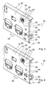
- FIG. 1 1 shows a schematic view of a domestic appliance device according to the invention with a protective conductor 32 and a safety grounding unit 12.
- the safety grounding unit 12 has a surface mounting unit 10, a grounding means 16, a carrier unit 14, a housing 28 and a protective contact 30.
- the safety grounding unit 12 forms a safety earth connection for the surface unit 10.
- a current of twenty five amperes is passed from a power source having an open circuit voltage below twelve volts AC or DC from the grounding pad 30 to the surface package 10, and that voltage drop occurring between the grounding pad 30 and the surface package 10 occurs, measured and calculated by means of the measured voltage drop and the current an ohmic resistance
- the ohmic resistance is less than or equal to one hundred milliohms.
- the protective contact 30 is connected to a protective conductor 32, whereby the protective contact 30 is grounded. Occurs a defect of the home appliance device, in which a current-carrying line touches the surface assembly 10 and touches an operator at the same time the surface assembly 10, the remains Health of the operator due to the safety grounding unit 12 and the grounding of the protective contact 30 without damage.
- the carrier unit 14 receives at least one weight force of the surface assembly 10 in the operating state ( FIG. 2 ).
- the surface construction unit 10 which can be touched by an operator and is designed as a decorative part, is fastened to the carrier unit 14 by means of a double adhesive tape 34 and polyurethane foam 36.
- the carrier unit 14 is conductively connected to the housing 28 and secured thereto. Furthermore, the housing 28 is conductively connected to the protective contact 30.
- the safety grounding unit 12 has a grounding means 16, which is fixed to the carrier unit 14 in a positive and non-positive manner ( Figures 2 . 3 . 4 and 5 ).
- the carrier unit 14 forms a rectangular recess 38, through which a bracket 40 of a clamping means 42 of the grounding means 16 protrudes.
- the clamping means 42 clamps a partial region 44 of the carrier unit 14 and is thereby fastened non-positively with respect to a vertical direction 46 on the carrier unit 14.
- a contact surface 50 of the grounding means 16 bears against a contact surface 52 of the carrier unit 14.
- the carrier unit 14 has a metal region, which forms the contact surface 52.
- the grounding means 16 is positively secured to the carrier unit 14 with respect to a horizontal plane extending direction 48.
- the bracket 40 projecting through the recess 38 prevents movement of the contact surface 52 of the grounding means 16 in the surface extension direction 48 out of the contact surface 50 by applying a force to the grounding means 16 in the surface extension direction 48 to the grounding means 16 at one of the support unit 14 formed boundary of the recess 38 abuts.
- the grounding means 16 formed of beryllium copper is formed as a spring means and conductively connects the surface assembly 10 and the support unit 14.
- the grounding means has a curved surface region 18, which rests against the surface assembly 10 in an assembled state.
- the grounding means 16 is disposed between the support unit 14 and the surface assembly 14, and the grounding means 16 is elastically deformed by the surface assembly 10 and the support unit 14.
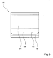
- the bracket 54 forms the curved surface area 18 (FIG. Figures 5 and 6 ).
- the grounding means 16 can be installed after attachment of the surface constructional unit 10 to the carrier unit 14.
- the grounding means 16 at a lateral region 58 (FIG. Figures 2 and 4 ) is inserted between the carrier unit 14 and the surface assembly 10 and the bracket 40 are inserted into the recess 38. This can be done in particular with tweezers.
- the carrier unit 14 has a surface 20 which is formed by a lacquer layer 22 of the carrier line 14 ( FIGS. 3 and 4 ).
- the lacquer layer 22 has a recess 24. A boundary of the recess 24 formed by the lacquer layer 22 also limits the contact surface 52 of the carrier unit 14.
- the carrier unit 14 has, in a completely installed and mounted state, a passage opening 26 to the surface assembly 10 (FIG. FIGS. 3 and 4 ).
- the passage opening 26 has a first mouth region 60 and a second mouth region 62.
- the first mouth region 60 is arranged on a first side 64 of the carrier unit 14, which faces the surface assembly 10.
- the second mouth region 62 is arranged on a second side of the carrier unit 14, which lies opposite the first side 64.
- the first mouth region 60 has a first point 68 and the second mouth region 62 has a second point 70.
- the points 68, 70 are arranged on a straight line 66 that intersects the surface unit 10 (FIG. FIGS. 2 to 4 ). Furthermore, the straight line 66 runs perpendicular to the contact surface 52.
- a front surface 72 of the integrally formed surface construction unit 10 is arranged to be touchable for an operator in an operating situation ( FIGS. 7 and 2 ).
- an electronic unit 74 with a cable is arranged in an area behind the carrier unit 14 and behind the passage opening 26. If the cable detaches in the event of a defect and an uninsulated region of the cable passes through the passage opening 26 and touches the surface assembly 10, an operator touching the surface assembly 10 is Protected by the safety grounding unit 12, so that his health remains intact.
- the safety grounding unit 12 is further designed as a functional grounding unit.
- the safety grounding unit 12 conducts charges, which are applied to the surface mount unit 10, for example, by an operating process, by means of the protective conductor 32 (FIG. FIG. 1 ) away from the domestic appliance, so that electronic components such. As the electronics unit 74, remain undisturbed by the charges in their function.
- the integrally formed grounding means 16 has a base portion 76 which, together with the bracket 40, forms the clamping means 42 ( FIG. 5 ).
- the base region 76 has a shape of a cuboid disc.
- the bracket 40 is formed on a first end portion 78 of the base portion 76.
- the second bracket 54 of the grounding means 16 is formed on a second end portion 80 of the base portion 76.
- the second end portion 80 is disposed on a side of the base portion 76 opposite to a side on which the first end portion 78 is disposed.
- One side 84 of the bracket 54 is opposite to another side 86 of the bracket, which is directly adjacent to the base portion 76 opposite.
- the curved surface area 18 is disposed on the side 84. In the side view of FIG.
- the base portion 76 has a main extension direction 88 and the bracket 54 a main extension direction 90, which enclose an angle 92 of 38.1 °.
- reference numeral 52 contact surface 10
- Harperman 54 hanger 12
- Safety grounding unit 56 direction 14
- support unit 58 Area 16 grounding means 60 mouth area 18 surface area 62 mouth area 20 surface 64 page 22 paint layer 66 Just 24 recess 68 Point 26 Through opening 70
- Point 28 casing 72 front surface 30 shockproof 74 electronics unit 32 protective conductor 76 basic area 34 Double-sided tape.
- end 36 Polyurethane foam 80 end 38 recess 84 page 40 hanger 86 page 42 clamping means 88
Landscapes
- Engineering & Computer Science (AREA)
- Chemical & Material Sciences (AREA)
- Combustion & Propulsion (AREA)
- Mechanical Engineering (AREA)
- General Engineering & Computer Science (AREA)
- Elimination Of Static Electricity (AREA)
- Combinations Of Kitchen Furniture (AREA)
- Electric Ovens (AREA)
- Electric Stoves And Ranges (AREA)
Claims (13)
- Equipement d'appareil ménager comprenant au moins un ensemble de surface (10) et au moins une unité de mise à la terre de sécurité (12) qui forme une connexion de mise à la terre de sécurité pour l'au moins un ensemble de surface (10), où l'au moins une unité de mise à la terre de sécurité (12) présente au moins un moyen de mise à la terre (16) qui est conçu comme un moyen élastique et exerce, au moins dans un état monté, une force élastique sur l'au moins un ensemble de surface (10).
- Equipement d'appareil ménager selon la revendication 1, caractérisé en ce que l'au moins une unité de mise à la terre de sécurité (12) présente au moins une unité de support (14) qui, au moins dans un état de fonctionnement, absorbe au moins une partie d'une force exercée par le poids de l'au moins un ensemble de surface (10).
- Equipement d'appareil ménager selon la revendication 2, caractérisé en ce que l'au moins un moyen de mise à la terre (16) est fixé sur l'unité de support (14), par complémentarité de forme et/ou par action de force.
- Equipement d'appareil ménager selon l'une quelconque des revendications précédentes, caractérisé en ce que l'au moins un moyen de mise à la terre (16) est, dans un état monté, déformé élastiquement par l'au moins un ensemble de surface (10).
- Equipement d'appareil ménager selon l'une quelconque des revendications précédentes, caractérisé en ce que l'au moins un moyen de mise à la terre (16) est constitué au moins partiellement de cuivre au béryllium.
- Equipement d'appareil ménager selon l'une quelconque des revendications précédentes, caractérisé en ce que l'au moins un moyen de mise à la terre (16) présente une zone de surface incurvée (18).
- Equipement d'appareil ménager au moins selon la revendication 2, caractérisé en ce que l'au moins une unité de support (14) est reliée de façon conductrice à l'au moins un ensemble de surface (10), par le moyen de mise à la terre (16).
- Equipement d'appareil ménager selon la revendication 7, caractérisé en ce que, lors d'un montage, l'au moins un moyen de mise à la terre (16) peut être intégré après une fixation de l'au moins un ensemble de surface (10) sur l'au moins une unité de support (14).
- Equipement d'appareil ménager au moins selon la revendication 2, caractérisé en ce que l'au moins une unité de support (14) présente une surface (20) qui est formée au moins partiellement par une couche de laque (22).
- Equipement d'appareil ménager selon la revendication 9, caractérisé en ce que la couche de laque (22) présente au moins un évidement (24).
- Equipement d'appareil ménager selon l'une quelconque des revendications précédentes, caractérisé en ce que l'au moins une unité de mise à la terre de sécurité (12) est conçue comme une unité de mise à la terre fonctionnelle.
- Equipement d'appareil ménager au moins selon la revendication 2, caractérisé en ce que l'au moins une unité de support (14) présente, dans un état monté, au moins une ouverture de passage (26) pour l'au moins un ensemble de surface (10).
- Appareil ménager comprenant un équipement d'appareil ménager selon l'une quelconque des revendications 1 à 12.
Priority Applications (1)
| Application Number | Priority Date | Filing Date | Title |
|---|---|---|---|
| PL09165899T PL2149754T3 (pl) | 2008-07-22 | 2009-07-20 | Urządzenie do sprzętu domowego |
Applications Claiming Priority (1)
| Application Number | Priority Date | Filing Date | Title |
|---|---|---|---|
| DE102008040619A DE102008040619A1 (de) | 2008-07-22 | 2008-07-22 | Hausgerätvorrichtung |
Publications (3)
| Publication Number | Publication Date |
|---|---|
| EP2149754A2 EP2149754A2 (fr) | 2010-02-03 |
| EP2149754A3 EP2149754A3 (fr) | 2011-07-13 |
| EP2149754B1 true EP2149754B1 (fr) | 2014-10-22 |
Family
ID=41328522
Family Applications (1)
| Application Number | Title | Priority Date | Filing Date |
|---|---|---|---|
| EP09165899.7A Active EP2149754B1 (fr) | 2008-07-22 | 2009-07-20 | Appareil ménager |
Country Status (3)
| Country | Link |
|---|---|
| EP (1) | EP2149754B1 (fr) |
| DE (1) | DE102008040619A1 (fr) |
| PL (1) | PL2149754T3 (fr) |
Family Cites Families (4)
| Publication number | Priority date | Publication date | Assignee | Title |
|---|---|---|---|---|
| DE8119275U1 (de) * | 1981-07-01 | 1982-09-02 | Schott Glaswerke, 6500 Mainz | Glaskeramik-kochfeld |
| DE19809224A1 (de) * | 1998-03-04 | 1999-09-09 | Bosch Siemens Hausgeraete | Haushaltsgerät |
| DE10314589B4 (de) * | 2003-03-31 | 2021-06-24 | BSH Hausgeräte GmbH | Gargerät |
| ITTO20060484A1 (it) * | 2006-06-30 | 2008-01-01 | Itw Ind Components Srl | Dispositivo di connessione elettrica a montaggio rapido e suo uso per la neutralizzazione di un terminale di uscita in alta tensione eccedente in un dispositivo accendigas elettronico per elettrodomestici, in particolare per un piano di cottura |
-
2008
- 2008-07-22 DE DE102008040619A patent/DE102008040619A1/de not_active Withdrawn
-
2009
- 2009-07-20 EP EP09165899.7A patent/EP2149754B1/fr active Active
- 2009-07-20 PL PL09165899T patent/PL2149754T3/pl unknown
Also Published As
| Publication number | Publication date |
|---|---|
| EP2149754A2 (fr) | 2010-02-03 |
| DE102008040619A1 (de) | 2010-01-28 |
| EP2149754A3 (fr) | 2011-07-13 |
| PL2149754T3 (pl) | 2015-04-30 |
Similar Documents
| Publication | Publication Date | Title |
|---|---|---|
| DE102009016756B4 (de) | Abschirmverbinderstruktur | |
| DE102014100142B4 (de) | Stecker | |
| DE202010017964U1 (de) | Elektrische Anschlussklemme | |
| EP0637099B1 (fr) | Barrettes à bornes munies de dispositifs de protection contre les surtensions | |
| EP2151908B1 (fr) | Machine dynamoélectrique dotée d'un boîtier de connexion en plusieurs parties | |
| DE202008004428U1 (de) | Steckverbinder mit einer Schirmauflage | |
| DE202014102609U1 (de) | Hochvolt-Verteilerbox insbesondere für ein Kraftfahrzeug | |
| DE102012104259B4 (de) | Gleichstrommotor zum Antrieb von Aggregaten eines Kraftfahrzeugs | |
| DE202013101698U1 (de) | Schutzleiterkontaktiersystem für Geräteanschlusssysteme elektrischer Geräte | |
| EP3510676A1 (fr) | Module de protection contre les surtensions pour un connecteur modulaire | |
| DE102004037083B4 (de) | Überspannungsableiter-Anordnung mit einer als Bestandteil eines Gehäuses ausführbaren Trägerplatte | |
| EP2645488A1 (fr) | Borne polaire pour un insert de prise | |
| DE202014103376U1 (de) | Geräteanschlusssystem mit integriertem Schutzleiteranschluss für elektrische Geräte | |
| EP2149754B1 (fr) | Appareil ménager | |
| DE102018209018A1 (de) | Hochvoltbordnetzanordnung für ein Kraftfahrzeug und Kraftfahrzeug | |
| DE102014216281A1 (de) | Steckverbinder für die Übertragung von Hochvoltstrom im Kfz-Bereich | |
| EP2489100B1 (fr) | Borne à vis avec couvercle et appareil de coupure d'installation | |
| WO2006050804A1 (fr) | Connexion electrique d'une broche avec un composant en tole | |
| WO2009103447A1 (fr) | Dispositif pour recevoir un composant électrique/électronique et procédé de montage correspondant, et élément de recouvrement pour un tel dispositif | |
| WO2009112320A1 (fr) | Bloc de raccordement à fonctions extensibles et module | |
| EP3796474B1 (fr) | Dispositif de raccordement permettant de contacter électriquement un appareil électrique | |
| DE102013104006B3 (de) | Schutzleiterkontaktiersystem | |
| DE102016106202B4 (de) | Abschirmvorrichtung und Anordnung mit einer Abschirmvorrichtung | |
| DE102014110344A1 (de) | Geräteanschlusssystem mit integriertem Schutzleiteranschluss für elektrische Geräte | |
| EP0758521A1 (fr) | Contact de prise de terre |
Legal Events
| Date | Code | Title | Description |
|---|---|---|---|
| PUAI | Public reference made under article 153(3) epc to a published international application that has entered the european phase |
Free format text: ORIGINAL CODE: 0009012 |
|
| AK | Designated contracting states |
Kind code of ref document: A2 Designated state(s): AT BE BG CH CY CZ DE DK EE ES FI FR GB GR HR HU IE IS IT LI LT LU LV MC MK MT NL NO PL PT RO SE SI SK SM TR |
|
| AX | Request for extension of the european patent |
Extension state: AL BA RS |
|
| RTI1 | Title (correction) |
Free format text: HOUSEHOLD APPARATUS |
|
| PUAL | Search report despatched |
Free format text: ORIGINAL CODE: 0009013 |
|
| AK | Designated contracting states |
Kind code of ref document: A3 Designated state(s): AT BE BG CH CY CZ DE DK EE ES FI FR GB GR HR HU IE IS IT LI LT LU LV MC MK MT NL NO PL PT RO SE SI SK SM TR |
|
| AX | Request for extension of the european patent |
Extension state: AL BA RS |
|
| 17P | Request for examination filed |
Effective date: 20120113 |
|
| 17Q | First examination report despatched |
Effective date: 20130409 |
|
| GRAP | Despatch of communication of intention to grant a patent |
Free format text: ORIGINAL CODE: EPIDOSNIGR1 |
|
| INTG | Intention to grant announced |
Effective date: 20140520 |
|
| GRAS | Grant fee paid |
Free format text: ORIGINAL CODE: EPIDOSNIGR3 |
|
| GRAA | (expected) grant |
Free format text: ORIGINAL CODE: 0009210 |
|
| AK | Designated contracting states |
Kind code of ref document: B1 Designated state(s): AT BE BG CH CY CZ DE DK EE ES FI FR GB GR HR HU IE IS IT LI LT LU LV MC MK MT NL NO PL PT RO SE SI SK SM TR |
|
| REG | Reference to a national code |
Ref country code: GB Ref legal event code: FG4D Free format text: NOT ENGLISH |
|
| REG | Reference to a national code |
Ref country code: CH Ref legal event code: EP |
|
| REG | Reference to a national code |
Ref country code: AT Ref legal event code: REF Ref document number: 692842 Country of ref document: AT Kind code of ref document: T Effective date: 20141115 |
|
| REG | Reference to a national code |
Ref country code: IE Ref legal event code: FG4D Free format text: LANGUAGE OF EP DOCUMENT: GERMAN |
|
| REG | Reference to a national code |
Ref country code: DE Ref legal event code: R096 Ref document number: 502009010120 Country of ref document: DE Effective date: 20141204 |
|
| REG | Reference to a national code |
Ref country code: CH Ref legal event code: PFA Owner name: BSH HAUSGERAETE GMBH, DE Free format text: FORMER OWNER: BSH BOSCH UND SIEMENS HAUSGERAETE GMBH, DE |
|
| REG | Reference to a national code |
Ref country code: NL Ref legal event code: VDEP Effective date: 20141022 |
|
| RAP2 | Party data changed (patent owner data changed or rights of a patent transferred) |
Owner name: BSH HAUSGERAETE GMBH |
|
| REG | Reference to a national code |
Ref country code: LT Ref legal event code: MG4D |
|
| PG25 | Lapsed in a contracting state [announced via postgrant information from national office to epo] |
Ref country code: LT Free format text: LAPSE BECAUSE OF FAILURE TO SUBMIT A TRANSLATION OF THE DESCRIPTION OR TO PAY THE FEE WITHIN THE PRESCRIBED TIME-LIMIT Effective date: 20141022 Ref country code: PT Free format text: LAPSE BECAUSE OF FAILURE TO SUBMIT A TRANSLATION OF THE DESCRIPTION OR TO PAY THE FEE WITHIN THE PRESCRIBED TIME-LIMIT Effective date: 20150223 Ref country code: NO Free format text: LAPSE BECAUSE OF FAILURE TO SUBMIT A TRANSLATION OF THE DESCRIPTION OR TO PAY THE FEE WITHIN THE PRESCRIBED TIME-LIMIT Effective date: 20150122 Ref country code: FI Free format text: LAPSE BECAUSE OF FAILURE TO SUBMIT A TRANSLATION OF THE DESCRIPTION OR TO PAY THE FEE WITHIN THE PRESCRIBED TIME-LIMIT Effective date: 20141022 Ref country code: IS Free format text: LAPSE BECAUSE OF FAILURE TO SUBMIT A TRANSLATION OF THE DESCRIPTION OR TO PAY THE FEE WITHIN THE PRESCRIBED TIME-LIMIT Effective date: 20150222 Ref country code: ES Free format text: LAPSE BECAUSE OF FAILURE TO SUBMIT A TRANSLATION OF THE DESCRIPTION OR TO PAY THE FEE WITHIN THE PRESCRIBED TIME-LIMIT Effective date: 20141022 Ref country code: NL Free format text: LAPSE BECAUSE OF FAILURE TO SUBMIT A TRANSLATION OF THE DESCRIPTION OR TO PAY THE FEE WITHIN THE PRESCRIBED TIME-LIMIT Effective date: 20141022 |
|
| REG | Reference to a national code |
Ref country code: PL Ref legal event code: T3 |
|
| REG | Reference to a national code |
Ref country code: DE Ref legal event code: R081 Ref document number: 502009010120 Country of ref document: DE Owner name: BSH HAUSGERAETE GMBH, DE Free format text: FORMER OWNER: BSH BOSCH UND SIEMENS HAUSGERAETE GMBH, 81739 MUENCHEN, DE Effective date: 20150407 |
|
| PG25 | Lapsed in a contracting state [announced via postgrant information from national office to epo] |
Ref country code: SE Free format text: LAPSE BECAUSE OF FAILURE TO SUBMIT A TRANSLATION OF THE DESCRIPTION OR TO PAY THE FEE WITHIN THE PRESCRIBED TIME-LIMIT Effective date: 20141022 Ref country code: CY Free format text: LAPSE BECAUSE OF FAILURE TO SUBMIT A TRANSLATION OF THE DESCRIPTION OR TO PAY THE FEE WITHIN THE PRESCRIBED TIME-LIMIT Effective date: 20141022 Ref country code: HR Free format text: LAPSE BECAUSE OF FAILURE TO SUBMIT A TRANSLATION OF THE DESCRIPTION OR TO PAY THE FEE WITHIN THE PRESCRIBED TIME-LIMIT Effective date: 20141022 Ref country code: GR Free format text: LAPSE BECAUSE OF FAILURE TO SUBMIT A TRANSLATION OF THE DESCRIPTION OR TO PAY THE FEE WITHIN THE PRESCRIBED TIME-LIMIT Effective date: 20150123 Ref country code: LV Free format text: LAPSE BECAUSE OF FAILURE TO SUBMIT A TRANSLATION OF THE DESCRIPTION OR TO PAY THE FEE WITHIN THE PRESCRIBED TIME-LIMIT Effective date: 20141022 |
|
| REG | Reference to a national code |
Ref country code: DE Ref legal event code: R097 Ref document number: 502009010120 Country of ref document: DE |
|
| REG | Reference to a national code |
Ref country code: FR Ref legal event code: PLFP Year of fee payment: 7 |
|
| PG25 | Lapsed in a contracting state [announced via postgrant information from national office to epo] |
Ref country code: SK Free format text: LAPSE BECAUSE OF FAILURE TO SUBMIT A TRANSLATION OF THE DESCRIPTION OR TO PAY THE FEE WITHIN THE PRESCRIBED TIME-LIMIT Effective date: 20141022 Ref country code: EE Free format text: LAPSE BECAUSE OF FAILURE TO SUBMIT A TRANSLATION OF THE DESCRIPTION OR TO PAY THE FEE WITHIN THE PRESCRIBED TIME-LIMIT Effective date: 20141022 Ref country code: CZ Free format text: LAPSE BECAUSE OF FAILURE TO SUBMIT A TRANSLATION OF THE DESCRIPTION OR TO PAY THE FEE WITHIN THE PRESCRIBED TIME-LIMIT Effective date: 20141022 Ref country code: RO Free format text: LAPSE BECAUSE OF FAILURE TO SUBMIT A TRANSLATION OF THE DESCRIPTION OR TO PAY THE FEE WITHIN THE PRESCRIBED TIME-LIMIT Effective date: 20141022 Ref country code: DK Free format text: LAPSE BECAUSE OF FAILURE TO SUBMIT A TRANSLATION OF THE DESCRIPTION OR TO PAY THE FEE WITHIN THE PRESCRIBED TIME-LIMIT Effective date: 20141022 |
|
| PLBE | No opposition filed within time limit |
Free format text: ORIGINAL CODE: 0009261 |
|
| STAA | Information on the status of an ep patent application or granted ep patent |
Free format text: STATUS: NO OPPOSITION FILED WITHIN TIME LIMIT |
|
| PG25 | Lapsed in a contracting state [announced via postgrant information from national office to epo] |
Ref country code: IT Free format text: LAPSE BECAUSE OF FAILURE TO SUBMIT A TRANSLATION OF THE DESCRIPTION OR TO PAY THE FEE WITHIN THE PRESCRIBED TIME-LIMIT Effective date: 20141022 |
|
| 26N | No opposition filed |
Effective date: 20150723 |
|
| REG | Reference to a national code |
Ref country code: FR Ref legal event code: CD Owner name: BSH HAUSGERATE GMBH, DE Effective date: 20151022 |
|
| PG25 | Lapsed in a contracting state [announced via postgrant information from national office to epo] |
Ref country code: MC Free format text: LAPSE BECAUSE OF FAILURE TO SUBMIT A TRANSLATION OF THE DESCRIPTION OR TO PAY THE FEE WITHIN THE PRESCRIBED TIME-LIMIT Effective date: 20141022 Ref country code: SI Free format text: LAPSE BECAUSE OF FAILURE TO SUBMIT A TRANSLATION OF THE DESCRIPTION OR TO PAY THE FEE WITHIN THE PRESCRIBED TIME-LIMIT Effective date: 20141022 |
|
| REG | Reference to a national code |
Ref country code: CH Ref legal event code: PL |
|
| GBPC | Gb: european patent ceased through non-payment of renewal fee |
Effective date: 20150720 |
|
| PG25 | Lapsed in a contracting state [announced via postgrant information from national office to epo] |
Ref country code: LU Free format text: LAPSE BECAUSE OF FAILURE TO SUBMIT A TRANSLATION OF THE DESCRIPTION OR TO PAY THE FEE WITHIN THE PRESCRIBED TIME-LIMIT Effective date: 20150720 |
|
| REG | Reference to a national code |
Ref country code: IE Ref legal event code: MM4A |
|
| PG25 | Lapsed in a contracting state [announced via postgrant information from national office to epo] |
Ref country code: LI Free format text: LAPSE BECAUSE OF NON-PAYMENT OF DUE FEES Effective date: 20150731 Ref country code: CH Free format text: LAPSE BECAUSE OF NON-PAYMENT OF DUE FEES Effective date: 20150731 Ref country code: GB Free format text: LAPSE BECAUSE OF NON-PAYMENT OF DUE FEES Effective date: 20150720 |
|
| REG | Reference to a national code |
Ref country code: FR Ref legal event code: PLFP Year of fee payment: 8 |
|
| PG25 | Lapsed in a contracting state [announced via postgrant information from national office to epo] |
Ref country code: IE Free format text: LAPSE BECAUSE OF NON-PAYMENT OF DUE FEES Effective date: 20150720 |
|
| REG | Reference to a national code |
Ref country code: AT Ref legal event code: MM01 Ref document number: 692842 Country of ref document: AT Kind code of ref document: T Effective date: 20150720 |
|
| PG25 | Lapsed in a contracting state [announced via postgrant information from national office to epo] |
Ref country code: AT Free format text: LAPSE BECAUSE OF NON-PAYMENT OF DUE FEES Effective date: 20150720 |
|
| PG25 | Lapsed in a contracting state [announced via postgrant information from national office to epo] |
Ref country code: MT Free format text: LAPSE BECAUSE OF FAILURE TO SUBMIT A TRANSLATION OF THE DESCRIPTION OR TO PAY THE FEE WITHIN THE PRESCRIBED TIME-LIMIT Effective date: 20141022 |
|
| PG25 | Lapsed in a contracting state [announced via postgrant information from national office to epo] |
Ref country code: SM Free format text: LAPSE BECAUSE OF FAILURE TO SUBMIT A TRANSLATION OF THE DESCRIPTION OR TO PAY THE FEE WITHIN THE PRESCRIBED TIME-LIMIT Effective date: 20141022 Ref country code: HU Free format text: LAPSE BECAUSE OF FAILURE TO SUBMIT A TRANSLATION OF THE DESCRIPTION OR TO PAY THE FEE WITHIN THE PRESCRIBED TIME-LIMIT; INVALID AB INITIO Effective date: 20090720 Ref country code: BG Free format text: LAPSE BECAUSE OF FAILURE TO SUBMIT A TRANSLATION OF THE DESCRIPTION OR TO PAY THE FEE WITHIN THE PRESCRIBED TIME-LIMIT Effective date: 20141022 |
|
| REG | Reference to a national code |
Ref country code: FR Ref legal event code: PLFP Year of fee payment: 9 |
|
| PG25 | Lapsed in a contracting state [announced via postgrant information from national office to epo] |
Ref country code: BE Free format text: LAPSE BECAUSE OF NON-PAYMENT OF DUE FEES Effective date: 20150731 |
|
| PG25 | Lapsed in a contracting state [announced via postgrant information from national office to epo] |
Ref country code: MK Free format text: LAPSE BECAUSE OF FAILURE TO SUBMIT A TRANSLATION OF THE DESCRIPTION OR TO PAY THE FEE WITHIN THE PRESCRIBED TIME-LIMIT Effective date: 20141022 |
|
| REG | Reference to a national code |
Ref country code: FR Ref legal event code: PLFP Year of fee payment: 10 |
|
| PGFP | Annual fee paid to national office [announced via postgrant information from national office to epo] |
Ref country code: FR Payment date: 20220725 Year of fee payment: 14 |
|
| REG | Reference to a national code |
Ref country code: DE Ref legal event code: R084 Ref document number: 502009010120 Country of ref document: DE |
|
| PG25 | Lapsed in a contracting state [announced via postgrant information from national office to epo] |
Ref country code: FR Free format text: LAPSE BECAUSE OF NON-PAYMENT OF DUE FEES Effective date: 20230731 |
|
| PGFP | Annual fee paid to national office [announced via postgrant information from national office to epo] |
Ref country code: DE Payment date: 20250731 Year of fee payment: 17 |
|
| PGFP | Annual fee paid to national office [announced via postgrant information from national office to epo] |
Ref country code: PL Payment date: 20250707 Year of fee payment: 17 Ref country code: TR Payment date: 20250716 Year of fee payment: 17 |