EP2149763A2 - Vorrichtung zur Aufnahme einer Steuerelektronik - Google Patents
Vorrichtung zur Aufnahme einer Steuerelektronik Download PDFInfo
- Publication number
- EP2149763A2 EP2149763A2 EP09166546A EP09166546A EP2149763A2 EP 2149763 A2 EP2149763 A2 EP 2149763A2 EP 09166546 A EP09166546 A EP 09166546A EP 09166546 A EP09166546 A EP 09166546A EP 2149763 A2 EP2149763 A2 EP 2149763A2
- Authority
- EP
- European Patent Office
- Prior art keywords
- receiving
- control electronics
- bearing block
- hood
- display
- Prior art date
- Legal status (The legal status is an assumption and is not a legal conclusion. Google has not performed a legal analysis and makes no representation as to the accuracy of the status listed.)
- Granted
Links
- XLYOFNOQVPJJNP-UHFFFAOYSA-N water Substances O XLYOFNOQVPJJNP-UHFFFAOYSA-N 0.000 claims abstract description 17
- 238000010438 heat treatment Methods 0.000 description 4
- 238000004519 manufacturing process Methods 0.000 description 4
- 239000006096 absorbing agent Substances 0.000 description 2
- 230000035939 shock Effects 0.000 description 2
- 238000011109 contamination Methods 0.000 description 1
- 230000001419 dependent effect Effects 0.000 description 1
- 238000011161 development Methods 0.000 description 1
- 230000018109 developmental process Effects 0.000 description 1
- 230000000694 effects Effects 0.000 description 1
- 238000009434 installation Methods 0.000 description 1
Images


Classifications
-
- F—MECHANICAL ENGINEERING; LIGHTING; HEATING; WEAPONS; BLASTING
- F24—HEATING; RANGES; VENTILATING
- F24H—FLUID HEATERS, e.g. WATER OR AIR HEATERS, HAVING HEAT-GENERATING MEANS, e.g. HEAT PUMPS, IN GENERAL
- F24H9/00—Details
- F24H9/20—Arrangement or mounting of control or safety devices
- F24H9/2007—Arrangement or mounting of control or safety devices for water heaters
- F24H9/2014—Arrangement or mounting of control or safety devices for water heaters using electrical energy supply
- F24H9/2028—Continuous-flow heaters
-
- F—MECHANICAL ENGINEERING; LIGHTING; HEATING; WEAPONS; BLASTING
- F24—HEATING; RANGES; VENTILATING
- F24H—FLUID HEATERS, e.g. WATER OR AIR HEATERS, HAVING HEAT-GENERATING MEANS, e.g. HEAT PUMPS, IN GENERAL
- F24H9/00—Details
- F24H9/20—Arrangement or mounting of control or safety devices
- F24H9/25—Arrangement or mounting of control or safety devices of remote control devices or control-panels
-
- H—ELECTRICITY
- H05—ELECTRIC TECHNIQUES NOT OTHERWISE PROVIDED FOR
- H05K—PRINTED CIRCUITS; CASINGS OR CONSTRUCTIONAL DETAILS OF ELECTRIC APPARATUS; MANUFACTURE OF ASSEMBLAGES OF ELECTRICAL COMPONENTS
- H05K5/00—Casings, cabinets or drawers for electric apparatus
- H05K5/0017—Casings, cabinets or drawers for electric apparatus with operator interface units
Definitions
- the present invention relates to a device for receiving a control electronics of an electronic water heater, which comprises a hood, the device at least comprising a bearing block, which comprises the control electronics.
- the invention is based on the object to provide an improved device for receiving an electronic control unit of an electronic water heater, which comprises a hood available, which is easy to install and inexpensive to create.
- the device according to the invention for receiving control electronics is based on generic devices characterized in that the bearing block has at least one spring strut, by means of which the control electronics can be pressed against the hood.
- the electronics comprise at least one display.
- the device for receiving control electronics comprises a viewing window.
- the device comprises a display which can be pressed against the viewing window.
- the buttons or push buttons of the display are easy to see, and on the other hand, that the buttons or the push buttons are protected against contamination and moisture.
- the device for receiving a control electronics on a bearing block which has guides and / or counter detents for at least one plug.
- the device for receiving a control electronics has a shock absorber, which comprises a piping and / or a wiring.
- the device for receiving control electronics has at least one latching hook by means of which it can be connected to the instantaneous water heater. As a result, the device can be quickly connected to the water heater or its piping and separated again from this.
- the device has at least one guide pin, by means of which the latching hook can be stabilized.
- Purpose of the invention is the inclusion of control electronics with or without display for an electrically controlled instantaneous water heater.
- a plastic receptacle has been developed, which has the task of pressing the display or the control electronics to the viewing window of the hood of the water heater.
- the keys attached to the control board should be pressed close to the hood's operating fields to shorten the shift travel.
- the invention is a bearing block, on the one hand can accommodate the electronics with or without display and on the other hand can be pressed by means of strut to the hood. Due to the shock absorbers, too much switching of the pushbuttons is prevented when the keys are pressed.
- the bearing block bridges the cavity between the heating block and the hood. Piping and / or cabling may be performed under the struts. In this case, the bearing block guides and counter detents for different plugs.
- the latching on the heating block can be designed so that a path compensation can be realized both when placing the hood and in manufacturing tolerances of the hood without losing the locking function.
- the device 1 for receiving an electronic control unit 2 has a bearing block 5, wherein the bearing block 5 receives the control electronics 2. Furthermore, the device has a strut 6a and 6b, by means of which the bearing block 5 and the control electronics integrated therein can be pressed against a hood 4.
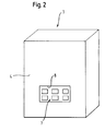
- Fig. 2 shows a water heater 3, the front side is closed by a hood 4.
- the hood 4 has a viewing window 8, against which a display 7 can be pressed.
- Fig. 3 shows a longitudinal sectional view of an embodiment of the device 1 to recognize are 4 struts 6a, 6b, 6c and 6d which are flexible to a limited extent, so move when loading the device 1, the struts apart on their side remote from a bearing block 5 side or Spread apart.
- a latching hook 9a By means of a latching hook 9a, the bearing block can be locked with the water heater.
- the device 1 guide pins 10 a, 10 b, 10 c and 10 d, by means of which the bearing block is stabilized and the latching hook is guided.
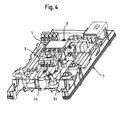
- Fig. 4 shows a perspective view of a heating block of a water heater 3 with attached device 1.
- the device 1 comprises a bearing block 5 and a viewing window 8 to further recognize struts 6a and 6b, by means of which the bearing block 5 is flexibly mounted.
- Fig. 5 shows a front view of a device 1, which includes a bearing block 5. This includes in its interior an electronics 2. In addition, the bearing block struts 6a and 6b.
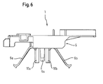
- Fig. 6 shows a side view of a device 1, which comprises a bearing block 5.
- the device 1 struts 6a and 6b, in addition to a latching hook 9a, with which the bearing block 5 can be locked with a water heater.
- the device 1 also has guide pins 10 a and 10 b, which stabilize the latching element and to prevent slipping within a counterpart with which the latching element 9 a is latched.
- Fig. 7 an oblique perspective view of a device 1, which comprises a bearing block 5.
- struts 6a, 6b and 6c. on its underside, the bearing block 5 struts 6a, 6b and 6c.
- the bearing block 5 has a latching element 9a, with which the bearing block 5 can be locked with a water heater.
- the locking element 9a is stabilized by guide pins 10a and 10b.
- the device of the invention combines in a low-cost and easy to install safety and ease of use.
Landscapes
- Engineering & Computer Science (AREA)
- Physics & Mathematics (AREA)
- Thermal Sciences (AREA)
- Chemical & Material Sciences (AREA)
- Combustion & Propulsion (AREA)
- Mechanical Engineering (AREA)
- General Engineering & Computer Science (AREA)
- Microelectronics & Electronic Packaging (AREA)
- Housings, Intake/Discharge, And Installation Of Fluid Heaters (AREA)
- Cookers (AREA)
- Selective Calling Equipment (AREA)
Abstract
Description
- Die vorliegende Erfindung betrifft eine Vorrichtung zur Aufnahme einer Steuerelektronik eines elektronischen Durchlauferhitzers, welcher eine Haube umfasst, die Vorrichtung wenigstens umfassend einen Lagerbock, welcher die Steuerelektronik umfasst.
- Vorrichtungen zur Aufnahme einer Steuerelektronik eines elektronischen Durchlauferhitzers sind im Stand der Technik bekannt. Dabei weisen die bestehenden Vorrichtungen den Nachteil auf, dass die Steuerelektronik an der Haube befestigt werden muss, um ein Verrutschen zu verhindern. Dies erhöht die Montagekosten einerseits und gestattet es andererseits nicht, mögliche Fertigungstoleranzen auszugleichen.
- Der Erfindung liegt die Aufgabe zu Grunde, eine verbesserte Vorrichtung zur Aufnahme einer Steuerelektronik eines elektronischen Durchlauferhitzers, der eine Haube umfasst, zur Verfügung zu stellen, die montagefreundlich und kostengünstig zu erstellen ist.
- Gelöst wird diese Aufgabe erfindungsgemäß mit den Merkmalen des Patentanspruches 1.
- Vorteilhafte Aus- und Weiterbildungen der Erfindung, welche einzeln oder in Kombination miteinander eingesetzt werden können, sind Gegenstand der Unteransprüche.
- Die erfindungsgemäße Vorrichtung zur Aufnahme einer Steuerelektronik baut auf gattungsgemäßen Vorrichtungen dadurch auf, dass der Lagerbock wenigstens ein Federbein aufweist, mittels dessen die Steuerelektronik gegen die Haube pressbar ist. Dadurch wird eine gegenüber dem Stand der Technik deutlich verbesserte Montagefreundlichkeit erzielt.
- Dadurch, dass der Lagerbock gegen die Haube pressbar ist, wird der Lagerbock an der Haube fixiert, und ein Verrutschen verhindert.
- In einer bevorzugten Variante umfasst die Elektronik wenigstens ein Display. Dadurch, dass das Federbein die Steuerelektronik gegen die Haube presst, wird erreicht, dass die Tasten, die auf einer Steuerplatine angebracht sind, nah an die Betätigungsfelder der Haube herangerückt werden, und der Schaltweg verkürzt wird. Auf Grund der Federbeine wird bei Tastenbetätigung ein zu hartes Schalten der Druckknöpfe verhindert. Durch die Vierpunktauflage ist jederzeit die definierte Lage des Displays bzw. der Taste zu den vorgesehenen Kontaktstellen zu der Haube definiert. Dadurch kann im Gegensatz zu einer, an der Haube fest montierten Steuerelektronik mit Display, auf eine, für diesen Montagefall nötige, Steuerleitung verzichtet werden. Zusätzlich können auf Grund der Federwirkung Fertigungstoleranzen ausgeglichen werden.
- Als besonders vorteilhaft hat es sich erwiesen, wenn die Vorrichtung zur Aufnahme einer Steuerelektronik ein Sichtfenster umfasst.
- Von besonderem Vorteil ist es dabei, wenn die Vorrichtung ein Display umfasst, welches gegen das Sichtfenster pressbar ist. Somit wird einerseits gewährleistet, dass die Tasten bzw. Druckknöpfe des Displays gut zu sehen sind, und andererseits, dass die Tasten bzw. die Druckknöpfe gegen Verschmutzen und Feuchtigkeit geschützt sind.
- In einer weitern bevorzugten Ausführungsform weist die Vorrichtung zur Aufnahme einer Steuerelektronik einen Lagerbock auf, der Führungen und/oder Gegenrastungen für wenigstens einen Stecker aufweist. Hierdurch lassen sich in sicherer und kostengünstiger Weise Elektroleitungen montieren.
- Von besonderem Vorteil ist es dabei, wenn die Vorrichtung zur Aufnahme einer Steuerelektronik ein Federbein aufweist, welches eine Verrohrung und/oder eine Verkabelung umfasst.
- Als vorteilhaft hat es sich insbesondere erweisen, wenn die Vorrichtung zur Aufnahme einer Steuerelektronik wenigstens einen Rasthaken aufweist, mittels dessen sie mit dem Durchlauferhitzer verbindbar ist. Dadurch kann die Vorrichtung schnell mit dem Durchlauferhitzer bzw. dessen Verrohrung verbunden und wieder von diesem getrennt werden.
- In einer weiteren Bevorzugten Ausführungsform weist die Vorrichtung wenigstens einen Führungsstift auf, mittels dessen der Rasthaken stabilisierbar ist.
- Die Erfindung lässt sich zutreffend wie folgt beschreiben:
- Zweck der Erfindung ist die Aufnahme einer Steuerelektronik mit oder ohne Display für einen elektrisch gesteuerten Durchlauferhitzer. Hierzu wurde eine Aufnahme aus Kunststoff entwickelt, die die Aufgabe hat, das Display bzw. die Steuerelektronik an das Sichtfenster der Haube des Durchlauferhitzers zu drücken. Zusätzlich sollen die Tasten, die an der Steuerplatine angebracht sind, nah an die Betätigungsfelder der Haube herangedrückt werden, um den Schaltweg zu verkürzen. Die Erfindung stellt einen Lagerbock dar, der einerseits die Elektronik mit oder ohne Display aufnehmen kann und andererseits mittels Federbein an die Haube gepresst werden kann. Aufgrund der Federbeine wird bei der Tastenbetätigung ein zu hartes Schalten der Druckknöpfe verhindert. Durch die Vierpunktauflage ist jederzeit die definierte Lage des Displays bzw. der Taste zu den vorgesehenen Kontaktstellen zu der Haube definiert. Dadurch, dass die Federbeine die Steuerelektronik mit oder ohne Display nah an die vorgesehenen Kontaktstellen der Haube heranführen, kann im Gegensatz zu einer, an der Haube fest montierten Steuerelektronik mit oder ohne Display, auf eine, für diesen Montagefall nötige Steuerleitung, verzichtet werden. Aufgrund der Federwirkung können Fertigungstoleranzen ausgeglichen werden. der Lagerbock überbrückt den Hohlraum zwischen Heizblock und Haube. Eine Verrohrung und/oder eine Verkablung kann unter den Federbeinen durchgeführt werden. Dabei weist der Lagerbock Führungen und Gegenrastungen für verschiedene Stecker auf. Zusätzlich kann dabei die Verrastung am Heizblock so ausgelegt sein, dass ein Wegausgleich sowohl beim Aufsetzen der Haube als auch bei Fertigungstoleranzen der Haube realisiert werden kann ohne die Rastfunktion zu verlieren.
- Weitere Vorteile und Ausgestaltungen der Erfindung werden im Folgenden anhand verschiedener Ausführungsbeispiele, auf welche die vorliegende Erfindung jedoch nicht beschränkt ist, sowie unter Bezugnahme auf die beiliegenden Zeichnungen erläutert. Bei der nachfolgenden Beschreibung der bevorzugten Ausführungsformen der vorliegenden Erfindung bezeichnen gleiche Bezugszeichen gleiche oder vergleichbare Komponenten.
- Darin zeigen schematisch:
- Fig. 1
- eine Querschnittszeichnung einer bevorzugte Ausführungsform der Vorrichtung;
- Fig. 2
- eine schematische Frontansicht eines Durchlauferhitzers mit eingesetztem Display;
- Fig. 3
- eine Längsschnittdarstellung einer Ausführungsform der Vorrichtung;
- Fig. 4
- eine perspektivische Darstellung eines Heizblocks eines Durchlauferhitzers mit aufgesetzter Vorrichtung;
- Fig. 5
- eine Vorderansicht einer Vorrichtung;
- Fig. 6
- eine Seitenansicht einer Vorrichtung; sowie
- Fig. 7
- eine perspektivische Schrägansicht einer Vorrichtung.
- Anhand der in
Fig. 1 gezeigten Querschnittszeichnung werden die einzelnen Komponenten der Vorrichtung zur Aufnahme einer Steuerelektronik illustriert. Die Vorrichtung 1 zur Aufnahme einer Steuerelektronik 2 weist einen Lagerbock 5 auf, wobei der Lagerbock 5 die Steuerelektronik 2 aufnimmt. Weiterhin weist die Vorrichtung ein Federbein 6a bzw. 6b auf, mittels dessen der Lagerbock 5 sowie die darin integrierte Steuerelektronik gegen eine Haube 4 pressbar ist. -
Fig. 2 zeigt einen Durchlauferhitzer 3, dessen Frontseite durch eine Haube 4 verschlossen ist. Die Haube 4 weist ein Sichtfenster 8 auf, gegen das ein Display 7 gepresst werden kann. Dadurch wird einerseits eine gute Zugänglichkeit der Displaytasten sowie andererseits ein guter Schutz durch das aufliegende Displayfenster erzielt. -
Fig. 3 zeigt eine Längsschnittdarstellung einer Ausführungsform der Vorrichtung 1. zu erkennen sind 4 Federbeine 6a, 6b, 6c sowie 6d die in einem begrenzten Maß flexibel sind, so dass sich bei Belastung der Vorrichtung 1 die Federbeine an ihrem von einem Lagerbock 5 entfernten Seite auseinander bewegen bzw. auseinander spreizen. Mittels eines Rasthakens 9a kann der Lagerbock mit dem Durchlauferhitzer verrastet werden. Darüber hinaus weist die Vorrichtung 1 Führungsstifte 10 a, 10b, 10c und 10d auf, mittels dessen der Lagerbock stabilisiert wird und der Rasthaken geführt wird. -
Fig. 4 zeigt eine perspektivische Darstellung eines Heizblocks eines Durchlauferhitzers 3 mit aufgesetzter Vorrichtung 1. Dabei umfasst die Vorrichtung 1 einen Lagerbock 5 sowie ein Sichtfenster 8. weiter zu erkennen sind Federbeine 6a und 6b, mittels derer der Lagerbock 5 flexibel gelagert ist. -
Fig. 5 zeigt eine Vorderansicht einer Vorrichtung 1, die einen Lagerbocks 5 umfasst. Dieser umfasst in seinem Innern eine Elektronik 2. Darüber hinaus weist der Lagerbock Federbeine 6a und 6b auf. -
Fig. 6 zeigt eine Seitenansicht einer Vorrichtung 1, die einen Lagerbocks 5 umfasst. Auf ihrer Unterseite weist die Vorrichtung 1 Federbeine 6a und 6b auf, darüber hinaus einen Rasthaken 9a, mit dem der Lagerbock 5 mit einem Durchlauferhitzer verrastet werden kann. Die Vorrichtung 1 weist darüber hinaus Führungsstifte 10 a und 10b auf, die das Rastelement stabilisieren und ein Verrutschen innerhalb eines Gegenstücks, mit dem das Rastelement 9a verrastet wird, zu vermeiden. -
Fig. 7 eine perspektivische Schrägansicht einer Vorrichtung 1, die einen Lagerbock 5 umfasst. Zu erkennen sind Federbeine 6a, 6b sowie 6c. auf seiner Unterseite weist der Lagerbock 5 Federbeine 6a, 6b und 6c auf. Ebenfalls auf seiner Unterseite weist der Lagerbock 5 ein Rastelement 9a auf, mit dem der Lagerbock 5 mit einem Durchlauferhitzer verrastet werden kann. Das Rastelement 9a wird durch Führungsstifte 10 a und 10 b stabilisiert. - Die erfindungsgemäße Vorrichtung vereint in preisgünstiger und montagefreundlicher Weise Sicherheit und Bedienkomfort.
-
- 1
- Vorrichtung zur Aufnahme einer Steuerelektronik
- 2
- Steuerelektronik; Elektronik
- 3
- Durchlauferhitzer
- 4
- Haube
- 5
- Lagerbock
- 6a; 6b; 6c; 6d
- Federbein
- 7
- Display
- 8
- Sichtfenster
- 9a; 9b; 9c
- Rasthaken
- 10a; 10b; 10c; 10d
- Führungsstift
- 11
- Gegenstück
Claims (8)
- Vorrichtung (1) zur Aufnahme einer Steuerelektronik (2) eines elektronischen Durchlauferhitzers (3), wobei der Durchlauferhitzer wenigstens eine Haube (4) umfasst, die Vorrichtung (1) wenigstens umfassend einen Lagerbock (5), welcher die Steuerelektronik (2) umfasst, dadurch gekennzeichnet, dass die Vorrichtung (1) wenigstens ein Federbein (6a; 6b; 6c; 6d) aufweist, mittels dessen der Lagerbock (5) gegen die Haube (4) pressbar ist.
- Vorrichtung (1) zur Aufnahme einer Steuerelektronik (2) nach Anspruch 1, dadurch gekennzeichnet, dass die Steuerelektronik (2) wenigstens ein Display (7) umfasst.
- Vorrichtung (1) zur Aufnahme einer Steuerelektronik (2) nach Anspruch 1 oder 2, dadurch gekennzeichnet, dass die Vorrichtung (1) ein Sichtfenster (8) umfasst.
- Vorrichtung (1) zur Aufnahme einer Steuerelektronik (2) nach einem der Ansprüche 2 bis 3, dadurch gekennzeichnet, dass das Display (7) gegen das Sichtfenster (8) pressbar ist.
- Vorrichtung (1) zur Aufnahme einer Steuerelektronik (2) nach einem der vorhergehenden Ansprüche, dadurch gekennzeichnet, dass der Lagerbock (5) Führungen und/oder Gegenrastungen für wenigstens einen Stecker aufweist.
- Vorrichtung (1) zur Aufnahme einer Steuerelektronik (2) nach einem der vorhergehenden Ansprüche, dadurch gekennzeichnet, dass das Federbein (6a;6b) eine Verrohrung und/oder eine Verkabelung umfasst.
- Vorrichtung (1) zur Aufnahme einer Steuerelektronik (2) nach einem der vorhergehenden Ansprüche, dadurch gekennzeichnet, dass die Vorrichtung wenigstens einen Rasthaken (9a; 9b; 9c; 9d) aufweist, mittels dessen die Vorrichtung mit dem Durchlauferhitzer (3) verbindbar ist.
- Vorrichtung (1) zur Aufnahme einer Steuerelektronik (2) nach einem der vorhergehenden Ansprüche, dadurch gekennzeichnet, dass die Vorrichtung wenigstens einen Führungsstift (10a; 10b; 10c; 10d) aufweist, mittels dessen der Rasthaken (9a; 9b; 9c; 9d) stabilisierbar ist.
Applications Claiming Priority (1)
| Application Number | Priority Date | Filing Date | Title |
|---|---|---|---|
| DE102008035904A DE102008035904A1 (de) | 2008-07-31 | 2008-07-31 | Vorrichtung zur Aufnahme einer Steuerelektronik |
Publications (3)
| Publication Number | Publication Date |
|---|---|
| EP2149763A2 true EP2149763A2 (de) | 2010-02-03 |
| EP2149763A3 EP2149763A3 (de) | 2015-04-08 |
| EP2149763B1 EP2149763B1 (de) | 2017-06-28 |
Family
ID=41066423
Family Applications (1)
| Application Number | Title | Priority Date | Filing Date |
|---|---|---|---|
| EP09166546.3A Not-in-force EP2149763B1 (de) | 2008-07-31 | 2009-07-28 | Vorrichtung zur Aufnahme einer Steuerelektronik |
Country Status (2)
| Country | Link |
|---|---|
| EP (1) | EP2149763B1 (de) |
| DE (1) | DE102008035904A1 (de) |
Cited By (2)
| Publication number | Priority date | Publication date | Assignee | Title |
|---|---|---|---|---|
| DE102017011636A1 (de) | 2017-12-15 | 2019-06-19 | Stiebel Eltron Gmbh & Co. Kg | Elektrisches Heizgerät und zugehöriges Montageverfahren |
| US20240357761A1 (en) * | 2021-08-31 | 2024-10-24 | Endress+Hauser SE+Co. KG | Device for receiving a display for an automation field device |
Families Citing this family (1)
| Publication number | Priority date | Publication date | Assignee | Title |
|---|---|---|---|---|
| DE102015204003A1 (de) | 2015-03-05 | 2016-09-08 | BSH Hausgeräte GmbH | Modularer Lagerbock für ein Haushalts-Installationsgerät |
Family Cites Families (3)
| Publication number | Priority date | Publication date | Assignee | Title |
|---|---|---|---|---|
| JP2001223526A (ja) * | 2000-02-07 | 2001-08-17 | Alps Electric Co Ltd | 電圧制御発振器 |
| US7046922B1 (en) * | 2005-03-15 | 2006-05-16 | Ion Tankless, Inc. | Modular tankless water heater |
| WO2007113613A1 (de) * | 2006-03-30 | 2007-10-11 | Erni Jaques V | Behälterloser heisswasserbereiter |
-
2008
- 2008-07-31 DE DE102008035904A patent/DE102008035904A1/de not_active Ceased
-
2009
- 2009-07-28 EP EP09166546.3A patent/EP2149763B1/de not_active Not-in-force
Cited By (2)
| Publication number | Priority date | Publication date | Assignee | Title |
|---|---|---|---|---|
| DE102017011636A1 (de) | 2017-12-15 | 2019-06-19 | Stiebel Eltron Gmbh & Co. Kg | Elektrisches Heizgerät und zugehöriges Montageverfahren |
| US20240357761A1 (en) * | 2021-08-31 | 2024-10-24 | Endress+Hauser SE+Co. KG | Device for receiving a display for an automation field device |
Also Published As
| Publication number | Publication date |
|---|---|
| EP2149763A3 (de) | 2015-04-08 |
| EP2149763B1 (de) | 2017-06-28 |
| DE102008035904A1 (de) | 2010-02-11 |
Similar Documents
| Publication | Publication Date | Title |
|---|---|---|
| DE112015001792B4 (de) | Direktsteck-Druckfederklemme mit Haltefeder | |
| DE19755018C1 (de) | Kartensicherung zum Sichern einer Leiterkarte | |
| EP2917970B1 (de) | Federkraftklemme mit einem betätigungsmittel | |
| CH697644B1 (de) | Aufbau zum Montieren eines Akkukastens auf einem elektrischen Fahrrad. | |
| DE102010039135A1 (de) | Vorrichtung zur Halterung von Systemen sowie Luft- oder Raumfahrzeug | |
| DE102017113063A1 (de) | Tragschienenbefestigung | |
| DE2039460A1 (de) | Mechanischer Rahmenaufbau fuer Fernmeldeanlagen | |
| DE102014115252A1 (de) | Elektrisches Steckverbinderpaar | |
| DE102013110481A1 (de) | Elektrische Anschlussklemme | |
| EP2149763B1 (de) | Vorrichtung zur Aufnahme einer Steuerelektronik | |
| EP1912293A1 (de) | Verriegelung an einer elektrischen Steckverbindung | |
| DE102014102886B4 (de) | Am Sitz montierter Schlossgeber | |
| DE102017123258A1 (de) | Türgriffanordnung eines Kraftfahrzeugs | |
| DE102017128604A1 (de) | Elektrische Steckverbindung zur Datenübertragung | |
| DE102016115733A1 (de) | Kraftfahrzeug-Griffanordnung | |
| EP2458688A1 (de) | Befestigungsvorrichtung zur Ausbildung einer elektrischen und/oder mechanischen Verbindung zwischen einer Stromschiene, Montageplatte oder leitenden Montagefläche und einer elektrischen Leitung | |
| DE60305530T2 (de) | Durchführungsvorrichtung für leitungen zwischen der karosserie und der tür eines fahrzeugs und fahrzeug mit dieser vorrichtung | |
| DE9407807U1 (de) | Kraftfahrzeug | |
| DE102014220489A1 (de) | Gehäuse für ein Steuergerät umfassend wenigsten eine Befestigungsplatte mit integrierter Wärmeleitstruktur | |
| DE102005006565A1 (de) | Vorrichtung zur Verriegelung und Entriegelung, insbesondere der Lehne eines Sitzes, insbesondere eines Kraftfahrzeugs, Vorrichtung mit einer Verriegelungsklinke, Vorrichtung mit einem Verschiebeelement, Vorrichtung mit einem ummantelten Verriegelungshaken und Kraftfahrzeugsitz mit einer erfindungsgemäßen Vorrichtung | |
| DE102014103713B3 (de) | Elektrisches/elektronisches Installationsgerät | |
| DE102018000658A1 (de) | Halterung für ein Telekommunikations-Endgerät und Verfahren zum Einführen eines Telekommunikations-Endgeräts | |
| EP2688379B1 (de) | Elektronische Baugruppe der Automatisierungstechnik | |
| EP1731914B1 (de) | Funktionseinheit für ein elektrisches oder elektronisches Gerät | |
| DE10242034B4 (de) | Teileinheit für eine Scheibenwaschanlage |
Legal Events
| Date | Code | Title | Description |
|---|---|---|---|
| PUAI | Public reference made under article 153(3) epc to a published international application that has entered the european phase |
Free format text: ORIGINAL CODE: 0009012 |
|
| AK | Designated contracting states |
Kind code of ref document: A2 Designated state(s): AT BE BG CH CY CZ DE DK EE ES FI FR GB GR HR HU IE IS IT LI LT LU LV MC MK MT NL NO PL PT RO SE SI SK SM TR |
|
| AX | Request for extension of the european patent |
Extension state: AL BA RS |
|
| PUAL | Search report despatched |
Free format text: ORIGINAL CODE: 0009013 |
|
| RAP1 | Party data changed (applicant data changed or rights of an application transferred) |
Owner name: BSH HAUSGERAETE GMBH |
|
| AK | Designated contracting states |
Kind code of ref document: A3 Designated state(s): AT BE BG CH CY CZ DE DK EE ES FI FR GB GR HR HU IE IS IT LI LT LU LV MC MK MT NL NO PL PT RO SE SI SK SM TR |
|
| AX | Request for extension of the european patent |
Extension state: AL BA RS |
|
| RIC1 | Information provided on ipc code assigned before grant |
Ipc: H05K 7/14 20060101ALI20150227BHEP Ipc: H05K 5/00 20060101ALI20150227BHEP Ipc: F24H 9/20 20060101AFI20150227BHEP |
|
| 17P | Request for examination filed |
Effective date: 20151008 |
|
| RBV | Designated contracting states (corrected) |
Designated state(s): AT BE BG CH CY CZ DE DK EE ES FI FR GB GR HR HU IE IS IT LI LT LU LV MC MK MT NL NO PL PT RO SE SI SK SM TR |
|
| GRAP | Despatch of communication of intention to grant a patent |
Free format text: ORIGINAL CODE: EPIDOSNIGR1 |
|
| INTG | Intention to grant announced |
Effective date: 20170207 |
|
| GRAS | Grant fee paid |
Free format text: ORIGINAL CODE: EPIDOSNIGR3 |
|
| GRAA | (expected) grant |
Free format text: ORIGINAL CODE: 0009210 |
|
| AK | Designated contracting states |
Kind code of ref document: B1 Designated state(s): AT BE BG CH CY CZ DE DK EE ES FI FR GB GR HR HU IE IS IT LI LT LU LV MC MK MT NL NO PL PT RO SE SI SK SM TR |
|
| REG | Reference to a national code |
Ref country code: GB Ref legal event code: FG4D Free format text: NOT ENGLISH |
|
| REG | Reference to a national code |
Ref country code: CH Ref legal event code: EP |
|
| REG | Reference to a national code |
Ref country code: AT Ref legal event code: REF Ref document number: 905234 Country of ref document: AT Kind code of ref document: T Effective date: 20170715 |
|
| REG | Reference to a national code |
Ref country code: IE Ref legal event code: FG4D Free format text: LANGUAGE OF EP DOCUMENT: GERMAN |
|
| REG | Reference to a national code |
Ref country code: DE Ref legal event code: R096 Ref document number: 502009014108 Country of ref document: DE |
|
| PG25 | Lapsed in a contracting state [announced via postgrant information from national office to epo] |
Ref country code: LT Free format text: LAPSE BECAUSE OF FAILURE TO SUBMIT A TRANSLATION OF THE DESCRIPTION OR TO PAY THE FEE WITHIN THE PRESCRIBED TIME-LIMIT Effective date: 20170628 Ref country code: NO Free format text: LAPSE BECAUSE OF FAILURE TO SUBMIT A TRANSLATION OF THE DESCRIPTION OR TO PAY THE FEE WITHIN THE PRESCRIBED TIME-LIMIT Effective date: 20170928 Ref country code: HR Free format text: LAPSE BECAUSE OF FAILURE TO SUBMIT A TRANSLATION OF THE DESCRIPTION OR TO PAY THE FEE WITHIN THE PRESCRIBED TIME-LIMIT Effective date: 20170628 Ref country code: FI Free format text: LAPSE BECAUSE OF FAILURE TO SUBMIT A TRANSLATION OF THE DESCRIPTION OR TO PAY THE FEE WITHIN THE PRESCRIBED TIME-LIMIT Effective date: 20170628 Ref country code: GR Free format text: LAPSE BECAUSE OF FAILURE TO SUBMIT A TRANSLATION OF THE DESCRIPTION OR TO PAY THE FEE WITHIN THE PRESCRIBED TIME-LIMIT Effective date: 20170929 |
|
| PGFP | Annual fee paid to national office [announced via postgrant information from national office to epo] |
Ref country code: CH Payment date: 20170727 Year of fee payment: 9 |
|
| REG | Reference to a national code |
Ref country code: NL Ref legal event code: MP Effective date: 20170628 |
|
| REG | Reference to a national code |
Ref country code: LT Ref legal event code: MG4D |
|
| PG25 | Lapsed in a contracting state [announced via postgrant information from national office to epo] |
Ref country code: BG Free format text: LAPSE BECAUSE OF FAILURE TO SUBMIT A TRANSLATION OF THE DESCRIPTION OR TO PAY THE FEE WITHIN THE PRESCRIBED TIME-LIMIT Effective date: 20170928 Ref country code: SE Free format text: LAPSE BECAUSE OF FAILURE TO SUBMIT A TRANSLATION OF THE DESCRIPTION OR TO PAY THE FEE WITHIN THE PRESCRIBED TIME-LIMIT Effective date: 20170628 Ref country code: LV Free format text: LAPSE BECAUSE OF FAILURE TO SUBMIT A TRANSLATION OF THE DESCRIPTION OR TO PAY THE FEE WITHIN THE PRESCRIBED TIME-LIMIT Effective date: 20170628 Ref country code: NL Free format text: LAPSE BECAUSE OF FAILURE TO SUBMIT A TRANSLATION OF THE DESCRIPTION OR TO PAY THE FEE WITHIN THE PRESCRIBED TIME-LIMIT Effective date: 20170628 |
|
| PGFP | Annual fee paid to national office [announced via postgrant information from national office to epo] |
Ref country code: AT Payment date: 20170821 Year of fee payment: 9 |
|
| PG25 | Lapsed in a contracting state [announced via postgrant information from national office to epo] |
Ref country code: SK Free format text: LAPSE BECAUSE OF FAILURE TO SUBMIT A TRANSLATION OF THE DESCRIPTION OR TO PAY THE FEE WITHIN THE PRESCRIBED TIME-LIMIT Effective date: 20170628 Ref country code: RO Free format text: LAPSE BECAUSE OF FAILURE TO SUBMIT A TRANSLATION OF THE DESCRIPTION OR TO PAY THE FEE WITHIN THE PRESCRIBED TIME-LIMIT Effective date: 20170628 Ref country code: CZ Free format text: LAPSE BECAUSE OF FAILURE TO SUBMIT A TRANSLATION OF THE DESCRIPTION OR TO PAY THE FEE WITHIN THE PRESCRIBED TIME-LIMIT Effective date: 20170628 Ref country code: EE Free format text: LAPSE BECAUSE OF FAILURE TO SUBMIT A TRANSLATION OF THE DESCRIPTION OR TO PAY THE FEE WITHIN THE PRESCRIBED TIME-LIMIT Effective date: 20170628 |
|
| REG | Reference to a national code |
Ref country code: DE Ref legal event code: R119 Ref document number: 502009014108 Country of ref document: DE |
|
| PG25 | Lapsed in a contracting state [announced via postgrant information from national office to epo] |
Ref country code: IS Free format text: LAPSE BECAUSE OF FAILURE TO SUBMIT A TRANSLATION OF THE DESCRIPTION OR TO PAY THE FEE WITHIN THE PRESCRIBED TIME-LIMIT Effective date: 20171028 Ref country code: IT Free format text: LAPSE BECAUSE OF FAILURE TO SUBMIT A TRANSLATION OF THE DESCRIPTION OR TO PAY THE FEE WITHIN THE PRESCRIBED TIME-LIMIT Effective date: 20170628 Ref country code: ES Free format text: LAPSE BECAUSE OF FAILURE TO SUBMIT A TRANSLATION OF THE DESCRIPTION OR TO PAY THE FEE WITHIN THE PRESCRIBED TIME-LIMIT Effective date: 20170628 Ref country code: SM Free format text: LAPSE BECAUSE OF FAILURE TO SUBMIT A TRANSLATION OF THE DESCRIPTION OR TO PAY THE FEE WITHIN THE PRESCRIBED TIME-LIMIT Effective date: 20170628 Ref country code: PL Free format text: LAPSE BECAUSE OF FAILURE TO SUBMIT A TRANSLATION OF THE DESCRIPTION OR TO PAY THE FEE WITHIN THE PRESCRIBED TIME-LIMIT Effective date: 20170628 |
|
| PG25 | Lapsed in a contracting state [announced via postgrant information from national office to epo] |
Ref country code: MC Free format text: LAPSE BECAUSE OF FAILURE TO SUBMIT A TRANSLATION OF THE DESCRIPTION OR TO PAY THE FEE WITHIN THE PRESCRIBED TIME-LIMIT Effective date: 20170628 |
|
| REG | Reference to a national code |
Ref country code: IE Ref legal event code: MM4A |
|
| PG25 | Lapsed in a contracting state [announced via postgrant information from national office to epo] |
Ref country code: DE Free format text: LAPSE BECAUSE OF NON-PAYMENT OF DUE FEES Effective date: 20180201 Ref country code: IE Free format text: LAPSE BECAUSE OF NON-PAYMENT OF DUE FEES Effective date: 20170728 Ref country code: DK Free format text: LAPSE BECAUSE OF FAILURE TO SUBMIT A TRANSLATION OF THE DESCRIPTION OR TO PAY THE FEE WITHIN THE PRESCRIBED TIME-LIMIT Effective date: 20170628 |
|
| REG | Reference to a national code |
Ref country code: BE Ref legal event code: MM Effective date: 20170731 |
|
| PLBE | No opposition filed within time limit |
Free format text: ORIGINAL CODE: 0009261 |
|
| STAA | Information on the status of an ep patent application or granted ep patent |
Free format text: STATUS: NO OPPOSITION FILED WITHIN TIME LIMIT |
|
| GBPC | Gb: european patent ceased through non-payment of renewal fee |
Effective date: 20170928 |
|
| 26N | No opposition filed |
Effective date: 20180329 |
|
| REG | Reference to a national code |
Ref country code: FR Ref legal event code: ST Effective date: 20180524 |
|
| PG25 | Lapsed in a contracting state [announced via postgrant information from national office to epo] |
Ref country code: LU Free format text: LAPSE BECAUSE OF NON-PAYMENT OF DUE FEES Effective date: 20170728 |
|
| PG25 | Lapsed in a contracting state [announced via postgrant information from national office to epo] |
Ref country code: GB Free format text: LAPSE BECAUSE OF NON-PAYMENT OF DUE FEES Effective date: 20170928 |
|
| PG25 | Lapsed in a contracting state [announced via postgrant information from national office to epo] |
Ref country code: BE Free format text: LAPSE BECAUSE OF NON-PAYMENT OF DUE FEES Effective date: 20170731 Ref country code: FR Free format text: LAPSE BECAUSE OF NON-PAYMENT OF DUE FEES Effective date: 20170828 Ref country code: SI Free format text: LAPSE BECAUSE OF FAILURE TO SUBMIT A TRANSLATION OF THE DESCRIPTION OR TO PAY THE FEE WITHIN THE PRESCRIBED TIME-LIMIT Effective date: 20170628 |
|
| PG25 | Lapsed in a contracting state [announced via postgrant information from national office to epo] |
Ref country code: MT Free format text: LAPSE BECAUSE OF FAILURE TO SUBMIT A TRANSLATION OF THE DESCRIPTION OR TO PAY THE FEE WITHIN THE PRESCRIBED TIME-LIMIT Effective date: 20170628 |
|
| REG | Reference to a national code |
Ref country code: CH Ref legal event code: PL |
|
| REG | Reference to a national code |
Ref country code: AT Ref legal event code: MM01 Ref document number: 905234 Country of ref document: AT Kind code of ref document: T Effective date: 20180728 |
|
| PG25 | Lapsed in a contracting state [announced via postgrant information from national office to epo] |
Ref country code: AT Free format text: LAPSE BECAUSE OF NON-PAYMENT OF DUE FEES Effective date: 20180728 Ref country code: CH Free format text: LAPSE BECAUSE OF NON-PAYMENT OF DUE FEES Effective date: 20180731 Ref country code: LI Free format text: LAPSE BECAUSE OF NON-PAYMENT OF DUE FEES Effective date: 20180731 |
|
| PG25 | Lapsed in a contracting state [announced via postgrant information from national office to epo] |
Ref country code: HU Free format text: LAPSE BECAUSE OF FAILURE TO SUBMIT A TRANSLATION OF THE DESCRIPTION OR TO PAY THE FEE WITHIN THE PRESCRIBED TIME-LIMIT; INVALID AB INITIO Effective date: 20090728 |
|
| PG25 | Lapsed in a contracting state [announced via postgrant information from national office to epo] |
Ref country code: CY Free format text: LAPSE BECAUSE OF NON-PAYMENT OF DUE FEES Effective date: 20170628 |
|
| PG25 | Lapsed in a contracting state [announced via postgrant information from national office to epo] |
Ref country code: MK Free format text: LAPSE BECAUSE OF FAILURE TO SUBMIT A TRANSLATION OF THE DESCRIPTION OR TO PAY THE FEE WITHIN THE PRESCRIBED TIME-LIMIT Effective date: 20170628 |
|
| PG25 | Lapsed in a contracting state [announced via postgrant information from national office to epo] |
Ref country code: TR Free format text: LAPSE BECAUSE OF FAILURE TO SUBMIT A TRANSLATION OF THE DESCRIPTION OR TO PAY THE FEE WITHIN THE PRESCRIBED TIME-LIMIT Effective date: 20170628 |
|
| PG25 | Lapsed in a contracting state [announced via postgrant information from national office to epo] |
Ref country code: PT Free format text: LAPSE BECAUSE OF FAILURE TO SUBMIT A TRANSLATION OF THE DESCRIPTION OR TO PAY THE FEE WITHIN THE PRESCRIBED TIME-LIMIT Effective date: 20170628 |