EP2149772B1 - Instrument de mesure de déplacement numérique - Google Patents
Instrument de mesure de déplacement numérique Download PDFInfo
- Publication number
- EP2149772B1 EP2149772B1 EP09166595A EP09166595A EP2149772B1 EP 2149772 B1 EP2149772 B1 EP 2149772B1 EP 09166595 A EP09166595 A EP 09166595A EP 09166595 A EP09166595 A EP 09166595A EP 2149772 B1 EP2149772 B1 EP 2149772B1
- Authority
- EP
- European Patent Office
- Prior art keywords
- spindle
- rotor
- stator
- outer circumference
- adjusting screw
- Prior art date
- Legal status (The legal status is an assumption and is not a legal conclusion. Google has not performed a legal analysis and makes no representation as to the accuracy of the status listed.)
- Active
Links
Images


Classifications
-
- G—PHYSICS
- G01—MEASURING; TESTING
- G01B—MEASURING LENGTH, THICKNESS OR SIMILAR LINEAR DIMENSIONS; MEASURING ANGLES; MEASURING AREAS; MEASURING IRREGULARITIES OF SURFACES OR CONTOURS
- G01B3/00—Measuring instruments characterised by the use of mechanical techniques
- G01B3/18—Micrometers
Definitions
- the present invention relates to a digital displacement measuring instrument for measuring a dimension of an object to be measured based on an axial displacement of a spindle.
- a digital micrometer using a feed screw has been known as one of digital displacement measuring instruments.
- the digital micrometer includes a body, a spindle screwed into the body to be axially advanced and retracted, an encoder for detecting a displacement of the spindle, and a display for digitally displaying the displacement of the spindle based on a detected value of the encoder.
- the encoder includes a stator provided on the body, and a rotor rotatable synchronously with the spindle and opposite to the stator by a slight gap.
- the displacement of the spindle relative to the body is detected as a rotation angle of the rotor relative to the stator.
- a rotor is supported by a rotor bushing that is axially movable relative to a spindle.
- the rotor bushing includes an engaging pin engaged with a key groove axially provided on the outer circumference of the spindle and restrains the movement of the spindle toward its inner end (an anvil) by an adjusting screw opposite to a stator of a body.
- the stator is supported by a stator bushing that is axially movable and is fitted to the outer circumference of an inner cylinder provided on the body and rotatably supporting the spindle.
- the stator bushing is biased toward the rotor bushing by a spring. While the stator is biased toward the rotor and the stator bushing faces the rotor bushing, the stator and rotor are opposite each other by a slight gap so as to detect a rotation angle of the rotor relative to the stator.
- a lead of a screw of a spindle to be screwed into a body is typically 0.5 mm or 0.65 mm to meet a standardized accuracy criteria.
- it is effective to enlarge the lead of the screw of the spindle.
- an encoder is required to enhance resolution in proportion to the size of the lead of the screw.
- significant measurement errors may be caused depending on the degree of assembly accuracy required for providing the encoder and the movement of the encoder when the accuracy of the digital micrometer is enhanced by enhancing resolution of the encoder.
- the stator is biased toward the rotor by the spring. Accordingly, when the rotor is rotated synchronically with the spindle relative to the stator, the stator may axially fluctuate slightly against the spring or incline to the spindle depending on the degree of accuracy of a surface between the stator bushing and rotor bushing that respectively hold the stator and rotor. Then, when the encoder has higher resolution to enhance the accuracy and efficiency, the movement of the stator is detected by the encoder having higher accuracy, which easily results in measurement errors.
- JP-A-2005-3441 and EP 1 486 753 A2 relate to a digital displacement measuring instrument comprising a main body, a spindle slidably provided at the main body, and an encoder accomodated in the main body for detecting displacement of the spindle to convert a value for the detected displacement to an electric signal, wherein the encoder has a rotor rotating in a peripheral direction of the spindle and a stator provided inside the main body at a position opposite to the rotor with a prespecified space therefrom, and wherein the stator is directly or indirectly via other component hooked in the main body at a position away with a prespecified space from the spindle.
- An object of the invention is to provide a digital displacement measuring instrument having high accuracy and efficiency.
- the spindle when the spindle is rotated for measurement, the spindle is advanced and retracted by the rotation of the spindle. Then, the displacement of the spindle is detected by the encoder, thereby measuring a dimension of an object based on the displacement of the spindle.
- the stator is fixed to the body via the stator holder in the vicinity of the spindle so as not to be displaceable in the axial direction of the spindle. Accordingly, even when the rotor holder and rotor are rotated synchronically with the spindle, measurement errors due to the movement of the stator can be avoided as much as possible.
- a screw portion of the spindle screwed into the body has a lead of 1 mm or more.
- the screw portion of the spindle has the lead of 1 mm or more , operability can be enhanced as compared to, for example, a traditional digital micrometer having a lead of 0.5 mm. Thus, the efficiency can be enhanced.
- the stator holder includes a stator holding portion that holds the stator on a first end and a fitted portion on a second end, the fitted portion being fitted to an outer circumference of a spindle support cylinder that is provided on the body and rotatably supports the outer circumference of the spindle, and the fitted portion is fixed to the spindle support cylinder.
- the stator holder includes the stator holding portion for holding the stator on the first end and the fitted portion fitted to the outer circumference of the spindle support cylinder that is provided on the body and rotatably supports the outer circumference of the spindle on the second end. Accordingly, only by fitting the fitted portion to the outer circumference of the spindle support cylinder and then fixing the fitted portion to the spindle support cylinder via a setscrew or the like, the stator can be fixed to the body to be accurately centered on the spindle. Thus, the digital displacement measuring instrument can be easily assembled while maintaining high accuracy.
- the orientation maintaining unit is provided between the rotor holder and position adjusting screw according to the above arrangement, the orientation of the rotor holder can be maintained by the orientation maintaining unit contacting both of the rotor holder and position adjusting screw so that the rotor holder is substantially orthogonal to the axis of the spindle.
- the two first abutment portions of the board are symmetric about the axis of the spindle and the two second abutment portions are symmetric about the axis of the spindle.
- the line connecting the two first abutment portions is substantially perpendicular to the line connecting the two second abutment portions.
- the position adjusting screw includes a board restricting portion to restrict the board from moving in a direction perpendicular to the axis of the spindle, and the board restricting portion is provided on an end surface of the position adjusting screw adjacent to the rotor holder and includes a recess to accommodate the board.
- the orientation maintaining unit can be restricted from moving in the direction perpendicular to the axis of the spindle of the board by adding the recess capable of accommodating the board of the orientation maintaining unit on the end surface of the position adjusting screw adjacent to the rotor holder provided on a traditional digital displacement measuring instrument. Accordingly, the movable range of the board of the orientation maintaining unit can be limited. Thus, the orientation maintaining unit does not contact the spindle and therefore does not prevent smooth rotation of the spindle.
- the spindle is screwed into the body via a sleeve and a thimble fitted to an outer circumference of the sleeve is fixed to the spindle.
- the digital displacement measuring instrument further includes: an operation sleeve rotatable relative to the spindle and including a first operation section provided to an outer end of the spindle and having a smaller diameter than a diameter of the sleeve and a second operation section fitted to an outer circumference of the thimble; and a constant-pressure mechanism provided either between the first operation section of the operation sleeve and the outer end of the spindle or between the second operation section of the operation sleeve and the outer circumference of the thimble, the constant-pressure mechanism running idle when a load more than a predetermined level is applied on the spindle.
- the operation sleeve is rotatable relative to the spindle, and includes the first operation section adjacent to the outer end of the spindle and having a smaller diameter than the diameter of the sleeve and the second operation section fitted to the outer circumference of the thimble.
- a digital displacement measuring instrument is exemplified by a digital micrometer in this exemplary embodiment, but the invention is not limited thereto.
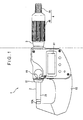
- Fig. 1 is a front view of a digital micrometer according to the exemplary embodiment.
- Fig. 2 is a partial cross-sectional view of the digital micrometer.
- a digital micrometer 1 includes: a substantially U-shaped body 10; a spindle 2 slidably provided on the body 10; an encoder 40 provided inside the body 10 for detecting the displacement of the spindle 2; and a display 61 for displaying the displacement (measured value) of the spindle 2 detected by the encoder 40.
- An anvil 10A is fixed to a first end of the body 10, and a bearing cylinder 11 (bushing) for supporting the spindle 2 in a slidable manner is provided on a second end of the body 10.
- the bearing cylinder 11 is substantially cylindrical.
- the spindle 2 is inserted into and supported by the inner circumference of the bearing cylinder 11.
- a clamping collar 161 is axially provided on the inner circumference of the bearing cylinder 11.
- a clamp screw 16 provided outside the body 10 is manipulated to tighten the spindle 2 by the clamping collar 161, thereby restricting the slide movement of the spindle 2.
- a substantially cylindrical inner cylinder 13 (spindle support cylinder) is provided on the body 10.
- a thimble 3 provided on the outer circumference of the inner cylinder 13 is rotated to advance and retract the spindle 2 relative to the anvil 10A.
- the spindle 2 includes a spindle body 21 and a screw shaft 22 that are linearly disposed.
- the spindle 2 also includes a key groove 23 axially provided on the outer circumference of the spindle body 21.
- the spindle 2 may be provided by a single cylindrical member or, alternatively, by separate members.
- the key groove 23 is V-shaped in cross section.
- the inner cylinder 13 provided in the axial direction of the spindle 2 has a first end supported by the body 10 and a second end carved with a female screw on the inner circumference thereof to be engaged with the screw shaft 22 of the spindle 2.
- the screw shaft 22 of the spindle 2 includes a screw portion including screws of which leads have 1 mm or more.
- the leads are preferably in a range of 1.5 mm to 2.54 mm.
- a male screw is carved on the outer circumference of the second end of the inner cylinder 13, to which a taper nut 4 is screwed.
- Three notches are provided on a predetermined section of the inner cylinder 13 at which the male screw is carved to define a three-way split portion 15.
- the taper nut 14 adjusts the fitting of the spindle 2 and the inner cylinder 13.
- the tightness applied by the three-way split portion 15 is changed to vary the inner diameter of the inner cylinder 13.
- the change in the inner diameter of the inner cylinder 13 allows adjustment of the fitting of the spindle 2 and the inner cylinder 13.
- An outer cylinder 17 is fixed to the outer circumference of the inner cylinder 13.
- the thimble 3 that is cylinder covering the outer circumference of the outer cylinder 17 is connected to an outer end (opposite to the anvil 10A) of the spindle 2 via a support shaft 32 and flange 37.
- An operation sleeve 4 is extended from the outer circumference of the thimble 3 to the outer end of the spindle 2.
- the operation sleeve 4 is rotatable relative to the spindle 2, and includes a first operation section 4A disposed in the vicinity of the outer end of the spindle 2 and having a smaller diameter than the diameter of the outer cylinder 17 and a second operation section 4B fitted into the first operation section 4A and fitted to the outer circumference of the outer cylinder 17.
- a constant-pressure mechanism 30 that runs idle when a load more than a predetermined level is applied on the spindle 2 is provided between the first operation section 4A of the operation sleeve 4 and the outer end of the spindle 2.
- the constant-pressure mechanism 30 may be alternatively provided between the second operation section 4B of the operation sleeve 4 and the outer circumference of the outer cylinder 17.
- the constant-pressure mechanism 30 includes: the support shaft 32 having a first end engaged with the outer end of the spindle 2 and a second end that rotatably supports the operation sleeve 4 via a screw 31; a first ratchet wheel 33 fixed to the inner circumference of the first operation section 4A; a second ratchet wheel 35 engaged with the first ratchet wheel 33, the second ratchet wheel 35 being not rotatable and being axially displaceable relative to the support shaft 32 via a key 34; a compression coil spring 36 that biases the second ratchet wheel 35 toward the first ratchet wheel 33; and the flange 37 that supports a first end of the compression coil spring 36 and is fixed to the support shaft 32.
- the first ratchet wheel 33 fixed to the first operation section 4A is integrally rotated. Since the first ratchet wheel 33 is engaged with the second ratchet wheel 35, the second ratchet wheel 35 is also rotated.
- the support shaft 32 is rotated via the key 34.
- the spindle 2 screwed with the support shaft 32 and the thimble 3 integrated with the spindle 2 are also rotated with the operation sleeve 4.
- the second ratchet wheel 35 While a load more than a predetermined level is applied on the spindle 2, the second ratchet wheel 35 is difficult to rotate. Thus, when the operation sleeve 4 is rotated to rotate the first ratchet wheel 33 at this time, the second ratchet wheel 35 is moved toward the compression coil spring 36 along the key 34 against the compression coil spring 36. In other words, the rotation force of the first ratchet wheel 33 is not transmitted to the second ratchet wheel 35 and therefore the operation sleeve 4 runs idle, thereby keeping constant pressure.
- the encoder 40 is an electromagnetic-induction-type encoder, which includes a rotor 41 rotating in the circumferential direction of the spindle 2 and a stator 42 fixed on the body and opposed to the rotor 41 with interposition of a predetermined gap.
- the rotor 41 is substantially doughnut-plate shaped and includes an electrode pattern of a coil (not shown) on a first surface adjacent to the stator 42.
- the rotor bushing 44 and rotor 41 may be integrated or, alternatively, may be provided by separate members.
- the rotor bushing 44 includes an engaging key 43 engageable with the key groove 23 of the spindle 2.
- a position adjusting screw 51 for restraining the rotor bushing 44 from moving in the direction opposite to the stator 42 axially along the spindle 2 is provided opposite to the stator 42 across the rotor bushing 44.
- An orientation maintaining unit 52 for maintaining an orientation of the rotor bushing 44 to be substantially orthogonal to the axis of the spindle 2 is provided between the rotor bushing 44 and the position adjusting screw 51.
- the position adjusting screw 51 covers the outer circumference of the spindle 2 opposite to the stator 42 across the rotor bushing 44 while being screwed to the inner circumference of the bearing cylinder 11 to be displaceable in the axial direction of the spindle 2.
- the stator 42 includes a substantially doughnut-plate shaped stator ring provided on the outer circumference of the spindle 2 and a plate shaped stator extension provided on the outer circumference of the stator ring to be stretched toward the inside of the body 10.
- the stator ring has an electrode pattern formed by a transmission coil and receive coil for detecting a rotation angle of the rotor 41 by electromagnetically connecting to the electrode pattern of the rotor 41.
- stator bushing 45 As shown in Fig. 3 , a surface of the stator ring, which is opposite to the rotor 41, is held by the stator bushing 45 (stator holder).
- the stator bushing 45 has a stator holding portion 451 for holding the stator 42 on a first end, and a fitted portion 452 to be fitted to the outer circumference of the inner end of the inner cylinder 13 on a second end.
- a setscrew 453 screwed from the outside of the body 10 is pressed against the fitted portion 452, thereby fixing the stator bushing 45 to the inner cylinder 13 (i.e., the body 10).
- the stator 42 is fixed to the inner cylinder 13 (i.e., the body 10) via the stator bushing 45 in the vicinity of the spindle 2 so as not to be displaceable in the axial direction of the spindle 2.
- the stator extension is fixed to the body 10 internally in the body 10.
- Fig. 4 shows a detailed arrangement in the vicinity of the rotor bushing of the digital micrometer according to the exemplary embodiment
- Fig. 5 is an exploded view of the orientation maintaining unit 52.
- the orientation maintaining unit 52 is provided between the rotor bushing 44 and position adjusting screw 51 to contact both the rotor bushing 44 and position adjusting screw 51, thereby maintaining the orientation of the rotor bushing 44 to be substantially orthogonal to the axis of the spindle 2.
- the orientation maintaining unit 52 includes: a substantially disk-shaped board 521; a substantially circular hole 521A provided in the board 521 and penetrated by the spindle 2; two first abutment portions 523 provided on a first surface of the board 521 to contact the position adjusting screw 51; two second abutment portions 522 provided on a second surface or the board 521 to contact the rotor bushing 44.
- the two first abutment portions 523 are substantially rectangular-parallelepiped protrusions provided to be symmetric about the axis of the spindle 2.
- the two second abutment portions 522 are substantially rectangular-parallelepiped protrusions provided to be symmetric about the axis of the spindle 2.
- the two first abutment portions 523 and two second abutment portions 522 are disposed so that a line connecting the two first abutment portions 523 is substantially perpendicular to a line connecting the two second abutment portions 522.
- the position adjusting screw 51 is substantially cylindrical and is fixed to the body 10 to cover the spindle 2.
- the position adjusting screw 51 includes: a flange 511 radially extending and provided on an end adjacent to the rotor bushing 44; and a movement restricting portion 512 (board restricting portion) for restricting the movement of the orientation maintaining unit 52 in the direction perpendicular to the axis of the spindle 2.
- the movement restriction portion 512 is provided on an end surface of the flange 511 adjacent to the rotor bushing 44 and is provided by a recess 511A that can accommodate the orientation maintaining unit 52.
- Fig. 6 shows a detailed arrangement in the vicinity of the rotor bushing when the position adjusting screw 51 is fixed to be inclined to the spindle 2.
- the digital micrometer 1 of the exemplary embodiment includes the orientation maintaining unit 52, even when the position adjusting screw 51 is fixed to be inclined to the spindle 2 as shown in Fig. 6 , the two first abutment portions 523 contact the position adjusting screw 51 at their upper ends to eliminate the influence of the inclination of the position adjusting screw 51. Thus, an appropriate orientation of the rotor bushing 44 can be maintained.
- the position adjusting screw 51 is fixed to be vertically inclined to the spindle 2.
- the two second abutment portions 522 contact the rotor bushing 44 at their ends to eliminate the influence of the inclination of the position adjusting screw 51, so that an appropriate orientation of the rotor bushing 44 can be also maintained.
- the thimble 3 is rotated to advance and retract the spindle 2 relative to the anvil 10A to bring an end of the spindle 2 and the anvil 10A into contact with a target portion of an object to be measured.
- the rotation of the spindle 2 is transmitted to the rotor 41 through the key grove 23, engaging key 43 and rotor bushing 44.
- the rotation angle of the rotor 41 detected by the encoder 40 is converted into the axial displacement of the spindle 2 to be displayed on the display 61.
- the stator 42 is fixed to the inner cylinder 13 via the stator bushing 45 in the vicinity of the spindle 2 so as not to be displaceable in the axial direction of the spindle 2 even when the rotor bushing 44 and rotor 41 are rotated synchronically with the spindle 2.
- measurement errors due to the movement of the stator 42 can be avoided as much as possible.
- the encoder 40 has high resolution for enhancing accuracy and efficiency, the axial movement of the stator 42 is not detected by the encoder 40 having high accuracy, thus providing a digital displacement measuring instrument having high accuracy and efficiency.
- the lead of the screw portion of the spindle 2 is 1 mm or more, operability can be enhanced as compared to, for example, a traditional digital micrometer having a lead of 0.5 mm. In other words, the efficiency can be enhanced.
- the stator bushing 45 includes the stator holding portion 451 for holding the stator 42 on the first end and the fitted portion 452 to be fitted to the outer circumference of the inner cylinder 13 that rotatably supports the outer circumference of the spindle 2 on the second end. Accordingly, simply by fitting the fitted portion 452 to the outer circumference of the inner cylinder 13 and fixing the fitted portion 452 to the inner cylinder 13 via the setscrew 453 or the like, the stator 42 can be fixed to the inner cylinder 13 (i.e., the body 10) to be accurately centered on the spindle 2. Thus, the digital micrometer 1 can be easily assembled while maintaining high accuracy.
- the orientation maintaining unit 52 is provided between the rotor bushing 44 and position adjusting screw 51 to contact both the rotor bushing 44 and position adjusting screw 51, the orientation maintaining unit 52 maintains the orientation of the rotor bushing 44 to be substantially orthogonal to the axis of the spindle 2 by contacting both the rotor bushing 44 and position adjusting screw 51.
- the movement of the rotor 41 (rotor bushing 44) during its rotation can be absorbed, thereby retaining high accuracy.
- the two first abutment portions 523 of the orientation maintaining unit 52 are symmetric about the axis of the spindle 2.
- the two second abutment portions 522 are symmetric about the axis of the spindle 2.
- the line connecting the two first abutment portions 523 is substantially perpendicular to the line connecting the two second abutment portions 522.
- the orientation maintaining unit 52 is a component having a simple shape, which includes: the substantially disk-shaped board 521; the hole 521A provided on the board 521 and penetrated by the spindle 2; the first abutment portions 523 that are two protrusions provided on the first surface of the board 521; the two second abutment portions 522 that are two protrusions provided on the second surface of the board 521.
- the orientation maintaining unit 52 can be manufactured at low cost from metals, resins or the like, thereby reducing cost for adding the orientation maintaining unit 52 to a traditional digital micrometer.
- the movable range of the orientation maintaining unit 52 can be limited.
- the orientation maintaining unit 52 does not contact the spindle 2 and thus does not prevent smooth rotation of the spindle 2.
- the orientation adjusting screw 51 is used also in a traditional digital micrometer, the movement of the orientation maintaining unit 52 in the direction perpendicular to the axis of the spindle 2 can be easily restricted only by adding the recess 511A capable of accommodating the orientation maintaining unit 52 on the end surface of the orientation adjusting screw 51 adjacent to the rotor bushing 44 provided in a traditional digital micrometer.
- the operation sleeve 4 is rotatable relative to the spindle 2, and includes the first operation section 4A disposed on the outer end of the spindle 2 and having a smaller diameter than the diameter of the outer cylinder 17 and the second operation section 4B fitted to the outer circumference of the thimble 3.
- the operation sleeve 4 is rotatable relative to the spindle 2, and includes the first operation section 4A disposed on the outer end of the spindle 2 and having a smaller diameter than the diameter of the outer cylinder 17 and the second operation section 4B fitted to the outer circumference of the thimble 3.
- orientation maintaining unit 52 The shape and the like of the orientation maintaining unit 52 are not limited to those described in the exemplary embodiment.
- the shape of the two first abutment portions 523 and two second abutment portions 522 is not limited to a substantially rectangular parallelepiped shape as exemplarily described in the exemplary embodiment, but may be a spherical shape, pillar shape, pyramidal or conical shape, or other shape.
- the board 521 of the orientation maintaining unit 52 includes the hole 521A to be penetrated by the spindle 2.
- the shape of the board 521 is not limited to a disk shape as exemplarily described in the exemplary embodiment.
- the board 521 may have a polygonal plate shape or other shape, and may be thick in the axial direction of the spindle 2.
- the hole 521A has a shape capable of being penetrated by the spindle 2.
- the shape of the hole 521A is not limited to a substantially circular shape as exemplarily described in the exemplary embodiment.
- the hole 52 1 A may have a polygonal shape or other shape.
- the movement restricting portion 512 is not limited to the layout, shape and the like described in the exemplary embodiment.
- the movement restricting portion 512 is exemplarily provided on the flange 511 of the position adjusting screw 51 in the exemplary embodiment, but is not limited thereto.
- the movement restricting portion 512 may be provided on the rotor bushing 44. t At this time, the same advantages can be also attained as in the exemplary embodiment.
- the engaging key 43 provided on the rotor bushing 44 is single while the key groove 23 provided on the spindle 2 is single in the exemplary embodiment, but other arrangement is possible.
- a plurality of engaging keys 43 may be provided on the rotor bushing 44 and, corresponding thereto, a plurality of key grooves 23 may be axially provided on the outer circumference of the spindle 2.
- the plurality of engaging keys 43 are slidably engaged on the spindle 2, so that the rotor 41 can be more securely positioned on the spindle 2 and thus shaky movement is not generated between the spindle 2 and the rotor 41.
- the digital displacement measuring instrument is exemplified by the digital micrometer 1 in the exemplary embodiment, but it can be modified as long as the modifications are covered by the claims.
- the digital displacement measuring instrument may be a digital micrometer head or the like, which includes the spindle 2 slidably provided on the body 10 and the encoder 40 for detecting the displacement of the spindle 2.
- the encoder 40 is not limited to the electromagnetic-induction-type encoder exemplarily described in the exemplary embodiment. It is only required that the encoder 40 is a digital encoder capable of detecting the relative rotation of the rotor 41 - relative to the stator 42.
- the encoder may be a optical linear encoder, electrostatic encoder or the like.
Landscapes
- Physics & Mathematics (AREA)
- General Physics & Mathematics (AREA)
- Length-Measuring Instruments Using Mechanical Means (AREA)
Claims (5)
- Instrument de mesure numérique de déplacement, comprenant:un corps (10) ;une tige (2) vissée dans le corps (10) de façon à être avancée et rétractée axialement ;un codeur (40) qui détecte un déplacement de la tige (2), dans lequelle codeur (40) comprend un rotor (41) tournant dans une direction circonférentielle de la tige (2), et un stator (42) disposé en regard du rotor (41) avec interposition d'un entrefer prédéterminé et prévu sur le corps (10),le rotor (41) est maintenu par un support de rotor (44) monté sur une circonférence externe de la tige (2) de façon à pouvoir être déplacé dans une direction axiale de la tige (2), le rotor (41) étant disposé en regard du stator (42) avec interposition de l'entrefer prédéterminé,le support de rotor (44) comprend une clavette d'enclenchement (43) apte à s'enclencher dans une rainure de clavette (23) prévue axialement sur la circonférence extérieure de la tige (2) et il est capable de se déplacer dans la direction axiale de la tige (2) à l'aide d'une vis de réglage de position (51),la vis de réglage de position (51) couvre la circonférence externe de la tige (2) en face du stator (42) de part et d'autre du support de rotor (44) et elle est vissée dans le corps (10) de façon à pouvoir être déplacée dans la direction axiale de la tige (2),le stator (42) est fixé au corps (10) par l'intermédiaire d'un support de stator (45) au voisinage de la tige (2) de façon à ne pas pouvoir être déplacé dans la direction axiale de la tige (2), etun dispositif de maintien d'orientation (52) prévu entre le support de rotor (44) et la vis de réglage de position (51) de façon à être en contact à la fois avec le support de rotor (44) et la vis de réglage de position (51) pour maintenir une orientation du support de rotor (44) de façon à ce qu'il soit sensiblement orthogonal à un axe de la tige (2), dans lequelle dispositif de maintien d'orientation (52) comprend : une plaque (521) prévue sur la circonférence externe de la tige (2) ; deux premières parties de butée (523) prévues sur une première surface d'extrémité de la plaque (521) et destinées à venir en contact avec la vis de réglage de position (51); et deux secondes parties de butée (522) prévues sur une seconde surface d'extrémité de la plaque (521) et destinées à venir en contact avec le support de rotor (44),les premières parties de butée (523) sont symétriques de part et d'autre de l'axe de la tige (2), les secondes parties de butée (522) sont symétriques de part et d'autre de l'axe de la tige (2), et une ligne reliant les deux premières parties de butée (523) est sensiblement perpendiculaire à une ligne reliant les deux secondes parties de butée (522).
- Instrument de mesure numérique de déplacement selon la revendication 1, dans lequel une partie vis (22) de la tige (2) vissée dans le corps (10) possède un pas réel de 1 mm ou plus.
- Instrument de mesure numérique de déplacement selon la revendication 1 ou la revendication 2, dans lequel le support de stator (45) comprend une partie de maintien de stator (451) qui maintient le stator (42) sur une première extrémité, et une partie ajustée (452) sur une seconde extrémité, la partie ajustée (452) étant ajustée sur une circonférence externe d'un cylindre de support de tige (13) qui est prévu sur le corps (10) et qui supporte à rotation la circonférence externe de la tige (2), et la partie ajustée (452) étant fixée au cylindre de support de tige (13).
- Instrument de mesure numérique de déplacement selon l'une quelconque des revendications 1 à 3, dans lequel
la vis de réglage de position (51) comprend une partie de restriction de déplacement de plaque (512) pour empêcher la plaque (521) de se déplacer dans une direction perpendiculaire à l'axe de la tige (2), et la partie de restriction de déplacement de plaque (512) est prévue sur une surface d'extrémité de la vis de réglage de position (51) de façon adjacente au support de rotor (44) et comprend un évidement (511 A) destiné à recevoir la plaque (512). - Instrument de mesure numérique de déplacement selon l'une quelconque des revendications 1 à 4, dans lequel
la tige (2) est vissée dans le corps (10) via un manchon (17), un fourreau (3) monté sur une circonférence externe du manchon (17) est fixé à la tige (2), l'instrument de mesure numérique de déplacement comprenant en outre : un manchon d'actionnement (4) apte à tourner par rapport à la tige (2) et comprenant une première section d'actionnement (4A) qui est prévue sur une extrémité externe de la tige (2) et dont le diamètre est inférieur à un diamètre du manchon (17), et une seconde section d'actionnement (4B) qui est montée sur une circonférence externe du fourreau (3) ; et
un mécanisme à pression constante (30) prévu soit entre la première section d'actionnement (4A) du manchon d'actionnement (4) et l'extrémité externe de la tige (2), soit entre la seconde section d'actionnement (4B) du manchon d'actionnement (4) et la circonférence externe du fourreau (3), le mécanisme à pression constante (30) tournant à vide lorsqu'une charge d'un niveau supérieur à un niveau prédéterminé est appliquée à la tige (2).
Applications Claiming Priority (1)
| Application Number | Priority Date | Filing Date | Title |
|---|---|---|---|
| JP2008194892A JP5265982B2 (ja) | 2008-07-29 | 2008-07-29 | デジタル式変位測定器 |
Publications (2)
| Publication Number | Publication Date |
|---|---|
| EP2149772A1 EP2149772A1 (fr) | 2010-02-03 |
| EP2149772B1 true EP2149772B1 (fr) | 2011-07-06 |
Family
ID=41168579
Family Applications (1)
| Application Number | Title | Priority Date | Filing Date |
|---|---|---|---|
| EP09166595A Active EP2149772B1 (fr) | 2008-07-29 | 2009-07-28 | Instrument de mesure de déplacement numérique |
Country Status (5)
| Country | Link |
|---|---|
| US (1) | US7877894B2 (fr) |
| EP (1) | EP2149772B1 (fr) |
| JP (1) | JP5265982B2 (fr) |
| CN (1) | CN101639352B (fr) |
| AT (1) | ATE515675T1 (fr) |
Families Citing this family (14)
| Publication number | Priority date | Publication date | Assignee | Title |
|---|---|---|---|---|
| CN1125969C (zh) * | 1998-07-21 | 2003-10-29 | 陈其良 | 一种电容式数显卡尺 |
| US8091251B1 (en) * | 2009-11-22 | 2012-01-10 | Yanchen Zhang | High-speed measuring electronic digital outside micrometer |
| JP5426464B2 (ja) * | 2010-04-16 | 2014-02-26 | 株式会社ミツトヨ | 変位測定器 |
| JP5426486B2 (ja) * | 2010-06-15 | 2014-02-26 | 株式会社ミツトヨ | 変位測定器 |
| JP5758762B2 (ja) | 2011-09-28 | 2015-08-05 | 株式会社ミツトヨ | 定圧装置及びマイクロメータ |
| JP5851882B2 (ja) | 2012-02-27 | 2016-02-03 | 株式会社ミツトヨ | デジタル式変位測定器 |
| US8739428B2 (en) * | 2012-07-03 | 2014-06-03 | Mitutoyo Corporation | Constant force spring actuator for a handheld micrometer |
| JP6275420B2 (ja) * | 2013-09-05 | 2018-02-07 | 株式会社ミツトヨ | マイクロメータ |
| US9478451B2 (en) * | 2014-02-10 | 2016-10-25 | Persimmon Technologies, Corp. | Robot having interchangeability features |
| RU2586086C1 (ru) * | 2015-04-07 | 2016-06-10 | Открытое акционерное общество "Научно-производственное предприятие "Радар ммс" | Датчик на поверхностных акустических волнах для беспроводного пассивного измерения перемещений |
| US9878443B2 (en) * | 2015-10-20 | 2018-01-30 | Jessem Products Limited | Adjustment assembly for marking gauge |
| CN105841729A (zh) * | 2016-03-25 | 2016-08-10 | 赵士立 | 一种套装式编码器 |
| JP2017220498A (ja) * | 2016-06-06 | 2017-12-14 | パナソニックIpマネジメント株式会社 | 部品実装装置及び部品実装方法 |
| FI3713058T3 (fi) * | 2019-03-20 | 2023-04-27 | Leine & Linde Ab | Mukautuvasti asennettava pyörimisanturi |
Family Cites Families (11)
| Publication number | Priority date | Publication date | Assignee | Title |
|---|---|---|---|---|
| US3686766A (en) * | 1970-04-02 | 1972-08-29 | Olympus Optical Co | Digital micrometer |
| JPS5750006U (fr) * | 1980-09-05 | 1982-03-20 | ||
| JP3623038B2 (ja) * | 1996-02-26 | 2005-02-23 | 株式会社ミツトヨ | マイクロメータ |
| JP3766801B2 (ja) * | 2001-12-28 | 2006-04-19 | 株式会社ミツトヨ | 測定器 |
| US7043852B2 (en) * | 2003-06-09 | 2006-05-16 | Mitutoyo Corporation | Measuring instrument |
| JP4516288B2 (ja) * | 2003-06-10 | 2010-08-04 | 株式会社ミツトヨ | デジタル式変位測定器 |
| DE102004006672B3 (de) * | 2004-02-11 | 2005-08-18 | Carl Mahr Holding Gmbh | Feinmessgerät zur Abstandsvermessung |
| JP4732050B2 (ja) * | 2005-07-22 | 2011-07-27 | 株式会社ミツトヨ | 測定器 |
| JP4825697B2 (ja) * | 2007-01-25 | 2011-11-30 | 株式会社ミツトヨ | デジタル式変位測定器 |
| JP5112779B2 (ja) * | 2007-08-03 | 2013-01-09 | 株式会社ミツトヨ | 絶対位置測定装置 |
| JP2009276137A (ja) * | 2008-05-13 | 2009-11-26 | Mitsutoyo Corp | デジタル表示式変位測定器 |
-
2008
- 2008-07-29 JP JP2008194892A patent/JP5265982B2/ja active Active
-
2009
- 2009-07-28 AT AT09166595T patent/ATE515675T1/de not_active IP Right Cessation
- 2009-07-28 CN CN200910152087.3A patent/CN101639352B/zh active Active
- 2009-07-28 EP EP09166595A patent/EP2149772B1/fr active Active
- 2009-07-29 US US12/511,735 patent/US7877894B2/en active Active
Also Published As
| Publication number | Publication date |
|---|---|
| US7877894B2 (en) | 2011-02-01 |
| CN101639352B (zh) | 2013-03-13 |
| EP2149772A1 (fr) | 2010-02-03 |
| JP2010032365A (ja) | 2010-02-12 |
| ATE515675T1 (de) | 2011-07-15 |
| JP5265982B2 (ja) | 2013-08-14 |
| CN101639352A (zh) | 2010-02-03 |
| US20100024237A1 (en) | 2010-02-04 |
Similar Documents
| Publication | Publication Date | Title |
|---|---|---|
| EP2149772B1 (fr) | Instrument de mesure de déplacement numérique | |
| US8033032B2 (en) | Inside diameter measuring tool | |
| EP1873476B1 (fr) | Instrument de mesure de déplacement numérique | |
| US7111413B2 (en) | Precision distance-measuring instrument | |
| EP1950524B1 (fr) | Micromètre à affichage numérique | |
| US6487897B1 (en) | Detector for surface texture measuring instrument | |
| JP2018069360A (ja) | 軸連結調整機構 | |
| EP2131140B1 (fr) | Micromètre | |
| US9404724B2 (en) | Digital displacement measuring instrument | |
| JP2576022B2 (ja) | 多座標フィーラ装置 | |
| CN107649697B (zh) | 超精密镗削刀座及其调节装置 | |
| US7500320B2 (en) | Position measuring arrangement and procedure for the assembly of a position measuring arrangement | |
| US9982985B2 (en) | Digital comparator having a retractable anvil supported at one end of a U-shaped frame | |
| CN218765064U (zh) | 一种校准装置 | |
| JPS61111409A (ja) | エンコ−ダ内蔵型測定器 | |
| JP2015021919A (ja) | ステージ装置および調整ユニット | |
| CN217331001U (zh) | 一种检测装置及回转支承生产线 | |
| JP3725151B2 (ja) | マイクロメータ | |
| JP3128248U (ja) | 芯出し器具 | |
| JP2007285814A (ja) | デジタル式変位測定器 | |
| CN121994103A (zh) | 触觉测量装置 | |
| JPS59180401A (ja) | マイクロメ−タ | |
| JP2008039604A (ja) | デジタル式変位測定器 | |
| JPS59180417A (ja) | 測定機 |
Legal Events
| Date | Code | Title | Description |
|---|---|---|---|
| PUAI | Public reference made under article 153(3) epc to a published international application that has entered the european phase |
Free format text: ORIGINAL CODE: 0009012 |
|
| AK | Designated contracting states |
Kind code of ref document: A1 Designated state(s): AT BE BG CH CY CZ DE DK EE ES FI FR GB GR HR HU IE IS IT LI LT LU LV MC MK MT NL NO PL PT RO SE SI SK SM TR |
|
| 17P | Request for examination filed |
Effective date: 20100803 |
|
| 17Q | First examination report despatched |
Effective date: 20100830 |
|
| GRAP | Despatch of communication of intention to grant a patent |
Free format text: ORIGINAL CODE: EPIDOSNIGR1 |
|
| RIC1 | Information provided on ipc code assigned before grant |
Ipc: G01B 3/18 20060101AFI20110111BHEP |
|
| GRAS | Grant fee paid |
Free format text: ORIGINAL CODE: EPIDOSNIGR3 |
|
| GRAA | (expected) grant |
Free format text: ORIGINAL CODE: 0009210 |
|
| AK | Designated contracting states |
Kind code of ref document: B1 Designated state(s): AT BE BG CH CY CZ DE DK EE ES FI FR GB GR HR HU IE IS IT LI LT LU LV MC MK MT NL NO PL PT RO SE SI SK SM TR |
|
| REG | Reference to a national code |
Ref country code: GB Ref legal event code: FG4D |
|
| REG | Reference to a national code |
Ref country code: CH Ref legal event code: EP |
|
| REG | Reference to a national code |
Ref country code: IE Ref legal event code: FG4D |
|
| REG | Reference to a national code |
Ref country code: DE Ref legal event code: R096 Ref document number: 602009001732 Country of ref document: DE Effective date: 20110825 |
|
| REG | Reference to a national code |
Ref country code: NL Ref legal event code: VDEP Effective date: 20110706 |
|
| PG25 | Lapsed in a contracting state [announced via postgrant information from national office to epo] |
Ref country code: SI Free format text: LAPSE BECAUSE OF FAILURE TO SUBMIT A TRANSLATION OF THE DESCRIPTION OR TO PAY THE FEE WITHIN THE PRESCRIBED TIME-LIMIT Effective date: 20110706 |
|
| PG25 | Lapsed in a contracting state [announced via postgrant information from national office to epo] |
Ref country code: MT Free format text: LAPSE BECAUSE OF FAILURE TO SUBMIT A TRANSLATION OF THE DESCRIPTION OR TO PAY THE FEE WITHIN THE PRESCRIBED TIME-LIMIT Effective date: 20110706 |
|
| REG | Reference to a national code |
Ref country code: AT Ref legal event code: MK05 Ref document number: 515675 Country of ref document: AT Kind code of ref document: T Effective date: 20110706 |
|
| PG25 | Lapsed in a contracting state [announced via postgrant information from national office to epo] |
Ref country code: NL Free format text: LAPSE BECAUSE OF FAILURE TO SUBMIT A TRANSLATION OF THE DESCRIPTION OR TO PAY THE FEE WITHIN THE PRESCRIBED TIME-LIMIT Effective date: 20110706 Ref country code: FI Free format text: LAPSE BECAUSE OF FAILURE TO SUBMIT A TRANSLATION OF THE DESCRIPTION OR TO PAY THE FEE WITHIN THE PRESCRIBED TIME-LIMIT Effective date: 20110706 Ref country code: HR Free format text: LAPSE BECAUSE OF FAILURE TO SUBMIT A TRANSLATION OF THE DESCRIPTION OR TO PAY THE FEE WITHIN THE PRESCRIBED TIME-LIMIT Effective date: 20110706 Ref country code: IS Free format text: LAPSE BECAUSE OF FAILURE TO SUBMIT A TRANSLATION OF THE DESCRIPTION OR TO PAY THE FEE WITHIN THE PRESCRIBED TIME-LIMIT Effective date: 20111106 Ref country code: LT Free format text: LAPSE BECAUSE OF FAILURE TO SUBMIT A TRANSLATION OF THE DESCRIPTION OR TO PAY THE FEE WITHIN THE PRESCRIBED TIME-LIMIT Effective date: 20110706 Ref country code: SE Free format text: LAPSE BECAUSE OF FAILURE TO SUBMIT A TRANSLATION OF THE DESCRIPTION OR TO PAY THE FEE WITHIN THE PRESCRIBED TIME-LIMIT Effective date: 20110706 Ref country code: NO Free format text: LAPSE BECAUSE OF FAILURE TO SUBMIT A TRANSLATION OF THE DESCRIPTION OR TO PAY THE FEE WITHIN THE PRESCRIBED TIME-LIMIT Effective date: 20111006 Ref country code: BE Free format text: LAPSE BECAUSE OF FAILURE TO SUBMIT A TRANSLATION OF THE DESCRIPTION OR TO PAY THE FEE WITHIN THE PRESCRIBED TIME-LIMIT Effective date: 20110706 Ref country code: PT Free format text: LAPSE BECAUSE OF FAILURE TO SUBMIT A TRANSLATION OF THE DESCRIPTION OR TO PAY THE FEE WITHIN THE PRESCRIBED TIME-LIMIT Effective date: 20111107 |
|
| PG25 | Lapsed in a contracting state [announced via postgrant information from national office to epo] |
Ref country code: LV Free format text: LAPSE BECAUSE OF FAILURE TO SUBMIT A TRANSLATION OF THE DESCRIPTION OR TO PAY THE FEE WITHIN THE PRESCRIBED TIME-LIMIT Effective date: 20110706 Ref country code: MC Free format text: LAPSE BECAUSE OF NON-PAYMENT OF DUE FEES Effective date: 20110731 Ref country code: PL Free format text: LAPSE BECAUSE OF FAILURE TO SUBMIT A TRANSLATION OF THE DESCRIPTION OR TO PAY THE FEE WITHIN THE PRESCRIBED TIME-LIMIT Effective date: 20110706 Ref country code: CY Free format text: LAPSE BECAUSE OF FAILURE TO SUBMIT A TRANSLATION OF THE DESCRIPTION OR TO PAY THE FEE WITHIN THE PRESCRIBED TIME-LIMIT Effective date: 20110706 Ref country code: GR Free format text: LAPSE BECAUSE OF FAILURE TO SUBMIT A TRANSLATION OF THE DESCRIPTION OR TO PAY THE FEE WITHIN THE PRESCRIBED TIME-LIMIT Effective date: 20111007 Ref country code: AT Free format text: LAPSE BECAUSE OF FAILURE TO SUBMIT A TRANSLATION OF THE DESCRIPTION OR TO PAY THE FEE WITHIN THE PRESCRIBED TIME-LIMIT Effective date: 20110706 |
|
| REG | Reference to a national code |
Ref country code: IE Ref legal event code: MM4A |
|
| PG25 | Lapsed in a contracting state [announced via postgrant information from national office to epo] |
Ref country code: SK Free format text: LAPSE BECAUSE OF FAILURE TO SUBMIT A TRANSLATION OF THE DESCRIPTION OR TO PAY THE FEE WITHIN THE PRESCRIBED TIME-LIMIT Effective date: 20110706 Ref country code: CZ Free format text: LAPSE BECAUSE OF FAILURE TO SUBMIT A TRANSLATION OF THE DESCRIPTION OR TO PAY THE FEE WITHIN THE PRESCRIBED TIME-LIMIT Effective date: 20110706 |
|
| PLBE | No opposition filed within time limit |
Free format text: ORIGINAL CODE: 0009261 |
|
| STAA | Information on the status of an ep patent application or granted ep patent |
Free format text: STATUS: NO OPPOSITION FILED WITHIN TIME LIMIT |
|
| PG25 | Lapsed in a contracting state [announced via postgrant information from national office to epo] |
Ref country code: EE Free format text: LAPSE BECAUSE OF FAILURE TO SUBMIT A TRANSLATION OF THE DESCRIPTION OR TO PAY THE FEE WITHIN THE PRESCRIBED TIME-LIMIT Effective date: 20110706 Ref country code: RO Free format text: LAPSE BECAUSE OF FAILURE TO SUBMIT A TRANSLATION OF THE DESCRIPTION OR TO PAY THE FEE WITHIN THE PRESCRIBED TIME-LIMIT Effective date: 20110706 Ref country code: IT Free format text: LAPSE BECAUSE OF FAILURE TO SUBMIT A TRANSLATION OF THE DESCRIPTION OR TO PAY THE FEE WITHIN THE PRESCRIBED TIME-LIMIT Effective date: 20110706 |
|
| 26N | No opposition filed |
Effective date: 20120411 |
|
| PG25 | Lapsed in a contracting state [announced via postgrant information from national office to epo] |
Ref country code: DK Free format text: LAPSE BECAUSE OF FAILURE TO SUBMIT A TRANSLATION OF THE DESCRIPTION OR TO PAY THE FEE WITHIN THE PRESCRIBED TIME-LIMIT Effective date: 20110706 |
|
| PG25 | Lapsed in a contracting state [announced via postgrant information from national office to epo] |
Ref country code: IE Free format text: LAPSE BECAUSE OF NON-PAYMENT OF DUE FEES Effective date: 20110728 |
|
| REG | Reference to a national code |
Ref country code: DE Ref legal event code: R097 Ref document number: 602009001732 Country of ref document: DE Effective date: 20120411 |
|
| PG25 | Lapsed in a contracting state [announced via postgrant information from national office to epo] |
Ref country code: MK Free format text: LAPSE BECAUSE OF FAILURE TO SUBMIT A TRANSLATION OF THE DESCRIPTION OR TO PAY THE FEE WITHIN THE PRESCRIBED TIME-LIMIT Effective date: 20110706 |
|
| PG25 | Lapsed in a contracting state [announced via postgrant information from national office to epo] |
Ref country code: ES Free format text: LAPSE BECAUSE OF FAILURE TO SUBMIT A TRANSLATION OF THE DESCRIPTION OR TO PAY THE FEE WITHIN THE PRESCRIBED TIME-LIMIT Effective date: 20111017 Ref country code: SM Free format text: LAPSE BECAUSE OF FAILURE TO SUBMIT A TRANSLATION OF THE DESCRIPTION OR TO PAY THE FEE WITHIN THE PRESCRIBED TIME-LIMIT Effective date: 20110706 |
|
| PG25 | Lapsed in a contracting state [announced via postgrant information from national office to epo] |
Ref country code: LU Free format text: LAPSE BECAUSE OF NON-PAYMENT OF DUE FEES Effective date: 20110728 |
|
| PG25 | Lapsed in a contracting state [announced via postgrant information from national office to epo] |
Ref country code: BG Free format text: LAPSE BECAUSE OF FAILURE TO SUBMIT A TRANSLATION OF THE DESCRIPTION OR TO PAY THE FEE WITHIN THE PRESCRIBED TIME-LIMIT Effective date: 20111006 |
|
| PG25 | Lapsed in a contracting state [announced via postgrant information from national office to epo] |
Ref country code: TR Free format text: LAPSE BECAUSE OF FAILURE TO SUBMIT A TRANSLATION OF THE DESCRIPTION OR TO PAY THE FEE WITHIN THE PRESCRIBED TIME-LIMIT Effective date: 20110706 |
|
| PG25 | Lapsed in a contracting state [announced via postgrant information from national office to epo] |
Ref country code: HU Free format text: LAPSE BECAUSE OF FAILURE TO SUBMIT A TRANSLATION OF THE DESCRIPTION OR TO PAY THE FEE WITHIN THE PRESCRIBED TIME-LIMIT Effective date: 20110706 |
|
| REG | Reference to a national code |
Ref country code: CH Ref legal event code: PL |
|
| PG25 | Lapsed in a contracting state [announced via postgrant information from national office to epo] |
Ref country code: CH Free format text: LAPSE BECAUSE OF NON-PAYMENT OF DUE FEES Effective date: 20130731 Ref country code: LI Free format text: LAPSE BECAUSE OF NON-PAYMENT OF DUE FEES Effective date: 20130731 |
|
| REG | Reference to a national code |
Ref country code: FR Ref legal event code: PLFP Year of fee payment: 8 |
|
| REG | Reference to a national code |
Ref country code: FR Ref legal event code: PLFP Year of fee payment: 9 |
|
| REG | Reference to a national code |
Ref country code: FR Ref legal event code: PLFP Year of fee payment: 10 |
|
| PGFP | Annual fee paid to national office [announced via postgrant information from national office to epo] |
Ref country code: DE Payment date: 20250722 Year of fee payment: 17 |
|
| PGFP | Annual fee paid to national office [announced via postgrant information from national office to epo] |
Ref country code: GB Payment date: 20250722 Year of fee payment: 17 |
|
| PGFP | Annual fee paid to national office [announced via postgrant information from national office to epo] |
Ref country code: FR Payment date: 20250724 Year of fee payment: 17 |