EP2149774B1 - Instrument und Verfahren zur Oberflächenstrukturmessung - Google Patents
Instrument und Verfahren zur Oberflächenstrukturmessung Download PDFInfo
- Publication number
- EP2149774B1 EP2149774B1 EP09166419A EP09166419A EP2149774B1 EP 2149774 B1 EP2149774 B1 EP 2149774B1 EP 09166419 A EP09166419 A EP 09166419A EP 09166419 A EP09166419 A EP 09166419A EP 2149774 B1 EP2149774 B1 EP 2149774B1
- Authority
- EP
- European Patent Office
- Prior art keywords
- workpiece
- elevation
- measurement
- detector
- action
- Prior art date
- Legal status (The legal status is an assumption and is not a legal conclusion. Google has not performed a legal analysis and makes no representation as to the accuracy of the status listed.)
- Active
Links
Images


Classifications
-
- G—PHYSICS
- G01—MEASURING; TESTING
- G01B—MEASURING LENGTH, THICKNESS OR SIMILAR LINEAR DIMENSIONS; MEASURING ANGLES; MEASURING AREAS; MEASURING IRREGULARITIES OF SURFACES OR CONTOURS
- G01B5/00—Measuring arrangements characterised by the use of mechanical techniques
- G01B5/0002—Arrangements for supporting, fixing or guiding the measuring instrument or the object to be measured
- G01B5/0004—Supports
-
- G—PHYSICS
- G01—MEASURING; TESTING
- G01B—MEASURING LENGTH, THICKNESS OR SIMILAR LINEAR DIMENSIONS; MEASURING ANGLES; MEASURING AREAS; MEASURING IRREGULARITIES OF SURFACES OR CONTOURS
- G01B5/00—Measuring arrangements characterised by the use of mechanical techniques
- G01B5/20—Measuring arrangements characterised by the use of mechanical techniques for measuring contours or curvatures
-
- G—PHYSICS
- G01—MEASURING; TESTING
- G01B—MEASURING LENGTH, THICKNESS OR SIMILAR LINEAR DIMENSIONS; MEASURING ANGLES; MEASURING AREAS; MEASURING IRREGULARITIES OF SURFACES OR CONTOURS
- G01B5/00—Measuring arrangements characterised by the use of mechanical techniques
- G01B5/28—Measuring arrangements characterised by the use of mechanical techniques for measuring roughness or irregularity of surfaces
Definitions
- the present invention relates to a surface texture measuring instrument for conducting form measurements such as roughness measurements and contour measurements, and a method of the measurement.
- the surface texture measuring instrument disclosed in Document 1 which includes a driving mechanism for moving the workpiece relatively with respect to a detector, conducts a provisional measurement before conducting a main measurement and totally automatically corrects a posture of the workpiece mounted on a table to the standard posture (i.e., a posture with which the main measurement is conducted) so as to conduct positioning of the workpiece.
- a measurement can be conducted in a short time.
- the positioning of the workpiece exemplarily includes adjustment (auto-setting) of an elevation position of the detector in the Z-axis direction (direction orthogonal to the measurement direction of the detector) and adjustment (auto-leveling) of an inclination angle of the workpiece for the measurement direction of the detector to be parallel to a measurement target surface of the workpiece.
- the surface texture measuring instrument disclosed in Document 1 is required to use a combination of a table inclination device for inclining the table and an electric column device for moving the detector in Z-axis direction, which tends to result in a large-scale system configuration of the surface texture measuring instrument. Accordingly, a wider installation space may be required or device cost may be increased.
- small-size portable surface texture measuring instruments for conducing a roughness measurement on a relatively small workpiece.
- a small-size surface texture measuring instrument includes: a driving unit for measuring the workpiece by moving a detector along the surface of the workpiece; and an electric unit for controlling the driving unit and processing detection signals from the detector.
- Such a small-size surface texture measuring instrument typically checks leveling of the workpiece manually. Manual leveling check tends to consume longer time for adjustment, and repeatability in measurements of the same point may be deteriorated.
- the documents US 4 888 984 A and US 5 253 429 A disclose an instrument and a method for measuring the surface texture of a workpiece.
- the instrument comprises a stage, an elevation inclination adjuster having a fulcrum and one moving unit, and a controller for measuring, computing and positioning.
- a preliminary measurement is carried out before the main measurement is started.
- Elevation inclination adjusters for use in a surface texture measuring instrument is known from the documents US 2003/0217592 A1 .
- This adjuster comprises a base and a table with a placement surface.
- the table can be elevated and inclined with respect to the base by two moving units which support the table on two points of action.
- the moving units can be driven independently of each other by a respective motor.
- Another inclination adjuster is disclosed in US 6 745 616 B1 (Fig. 15).
- the table can be pivoted by manually adjusting two micrometer screws which support the table on two points of action. A fulcrum is arranged between the two points of action.
- An object of the invention is to provide a surface texture measuring instrument and a measuring method capable of conducting a positioning of a workpiece with a compact configuration and capable of enhancing operability of the positioning.
- a surface texture measuring instrument comprises:
- the elevation inclination adjuster capable of adjusting the elevation position and the inclination angle of the table
- the elevation movement and the inclination movement of the workpiece or the measuring device can be performed by a single device when a preliminary measurement and a main measurement are conducted.
- the positioning of the workpiece can be performed with a compact configuration.
- the positioning controller can perform the positioning of the workpiece based on the inclination angle obtained by the computing unit.
- automation of the positioning can be facilitated and operability of the positioning can be enhanced.
- the surface texture measuring instrument preferably further includes: an external device worked in conjunction with the measuring device; and an external controller that controls the external device and performs inputting and outputting of control signals between the controller and the external controller.
- the surface texture measuring instrument since the surface texture measuring instrument includes the external device such as a workpiece feeder and performs the inputting and outputting of the control signals such as measurement start/stop signals and status signals between the external controller and the controller, construction of an automatic inspection system can be facilitated.
- a system for remotely administering operations of the surface texture measurement through the external controller and a system for automatically performing a sorting of products (i.e., workpiece) into non-defective products and defective products and assortment thereof by making a pass-fail decision based on the measurement result through the external controller. Construction of such systems can be facilitated. In other words, a step for measuring surface texture can be easily incorporated into a manufacturing line and an inspection line.
- the invention also provides a method of measuring surface texture of a workpiece with use of a surface texture measuring instrument, the surface texture measuring instrument comprising a measuring device that comprises: a detector that detects the surface texture of the workpiece; and a movement mechanism that guides the detector movably in a measurement direction; an elevation inclination adjuster that comprises a table on which either one of the workpiece and the measuring device is mounted, the elevation inclination adjuster being capable of adjusting an elevation position and an inclination angle of the table a stage on which the other one of the workpiece and the measuring device is mounted; and a controller that controls the measuring device and the elevation inclination adjuster, the elevation inclination adjuster comprising: a base ; a table having two points of action in a direction parallel to a placement surface and a fulcrum between the two points of action (522); a pair of moving units that support the points of action of the table and moves the points of action in a direction for an interval between the respective points of action and the base to be increased or decreased; and
- the method of measuring a workpiece includes the first auto-setting, the preliminary measuring, the automatic escaping, the automatic inclining, the second auto-setting and the main measuring, automatic measurement can be realized, and the same advantages that the above surface texture measuring instrument provides can be obtained.
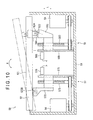
- Fig. 1 shows the entire structure of a surface texture measuring instrument 1 according to the first exemplary embodiment.
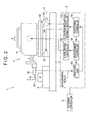
- Fig. 2 is a block diagram for explaining a structure of a controller for the surface texture measuring instrument 1.
- the surface texture measuring instrument 1 which is for conducting form measurements on a workpiece W such as roughness measurements and contour measurements, includes: a platform 2; a stage 3 on which the workpiece W is placed; a measuring device 4; an elevation inclination adjuster 5 (auto-setting/auto-leveling table) on which the measuring device 4 is placed; and a controller 6 for automatically conducting a positioning of the measuring device 4 relative to the workpiece W.
- the measuring device 4 is movable by the elevation inclination adjuster 5.
- a workpiece feeder 7 (external device worked in conjunction with the measuring device 4) and a parts box 8 are placed on the platform 2.
- An external controller 9 for controlling the workpiece feeder 7 is provided by PLC and a control box, and connected with the controller 6.
- the workpiece feeder 7 includes an arm 71 extendable between the stage 3 and the parts box 8.
- a head 72 attached on the distal end of the arm 71 is capable of placing a workpiece W accommodated in the parts box 8 onto the stage 3.
- the controller 6 is fed with measurement start/stop signals from the external controller 9 while the external controller 9 is fed with status signals from the controller 6 such as ready signals, OK/NG signals, measurement error signals and abnormal signals of the measuring device 4.
- the controller 6 includes an electric portion 6A and an I/O option board 6B (external control I/O), and the signals from the external controller 9 are transmitted to the electric portion 6A via the I/O option board 6B.
- I/O option board 6B external control I/O
- the measuring device 4 includes: an X-axis movement mechanism 41 placed on the elevation inclination adjuster 5; and a detector 42 mounted on the X-axis movement mechanism 41 in a manner movable in an X-axis direction.
- the X-axis direction is coincident with a measurement direction of the detector 42.
- the detector 42 which includes: a measurement arm 43 extended in the X-axis direction; and a stylus 44 (contact piece) mounted on the distal end of the measuring arm 43, is capable of detecting a displacement amount by which the stylus 44 is displaced in a Z-axis direction when the stylus 44 contacts the workpiece W.
- the Z-axis direction is a direction orthogonal to the X-axis direction (i.e., measurement direction).
- the measuring device 4 moves the measurement arm 43 in the X-axis direction while maintaining the contact of the stylus 44 on the workpiece W, so that the stylus 44 is displaced in the Z-axis direction in a manner following the irregularities of the surface contour of the workpiece W.
- the measuring device 4 is capable of measuring the contour and surface roughness of the workpiece W based on the detected oscillation amount.
- the elevation inclination adjuster 5 includes: a base 51 mounted on the platform 2; a table 52 movably supported on the base 51; a moving unit (not shown) for moving the table 52; and a pair of driving sources 54 for driving the moving unit.
- the elevation inclination adjuster 5 is for elevating the measuring device 4 mounted on the table 52 along an L-axis direction as well as for swinging the measuring device 4 around an R axis.
- the L-axis direction may be exemplarily the vertical direction.
- the R axis is an axis orthogonal to a plane within which the X axis and the Z axis related to the measuring device 4 extend.
- to swing the measuring device 4 around the R axis means to incline the measuring device 4 to the horizontal plane.
- the controller 6 which includes an X-axis driving controller 61, a measurement controller 62, an elevation-inclination driving controller 63, a positioning controller 64 and a computing unit 65, is exemplarily provided by a micro computer, a data processor and various programs built in these equipments.
- the X-axis driving controller 61 controls the X-axis movement mechanism 41 to be driven when preliminary measurements and main measurements are conducted on the workpiece W with use of the measuring device 4.
- the measurement controller 62 transmits control signals to the X-axis driving controller 61.
- the elevation-inclination driving controller 63 controls the pair of driving sources 54 of the elevation inclination adjuster 5 to be driven when the positioning is performed with use of the elevation inclination adjuster 5.
- the positioning controller 64 transmits control signals to the elevation-inclination driving controller 63 and transmits positioning-completion signals to the measurement controller 62.
- the computing unit 65 acquires results of preliminary measurements from the detector 42 upon receipt of measurement implementation signals from the measurement controller 62, and computes an error of the posture of the workpiece W with respect to the standard posture (i.e., posture when main measurements are conducted).
- the computing unit 65 transmits signals corresponding to the computed results to the positioning controller 64, and acquires results of main measurements from the detector 42 for analysis processing.
- Fig. 3 is a flow diagram for explaining the steps for measuring the surface texture of the workpiece W.
- the workpiece W is placed on the stage 3 (workpiece setting step: S1), and a measurement is initiated (S2).
- the detector 42 of the measuring device 4 is vertically moved (auto-set) to a position where the detector 42 can detect the workpiece W, and brought closer to the workpiece W (first auto-setting step: S3).
- the measuring device 4 is lifted down.
- the measuring device 4 preliminarily measures the workpiece W (preliminary measurement step: S4).
- the measurement controller 62 Fig. 2
- the detector 42 is moved in the X-axis direction to scan the surface of a measurement target portion of the workpiece W, and controlled to output the measurement result to the computing unit 65 ( Fig. 2 ).
- the measuring device 4 is automatically escaped therefrom by a designated amount (automatic escape step: S5).
- the positioning controller 64 operates the elevation inclination adjuster 5 to lift up the measuring device 4 by a designated amount, in order to prevent the detector 42 from interfering with the workpiece W when the measuring device 4 is inclined in the later-described automatic inclination step S6.
- the computing unit 65 computes an error of the posture of the workpiece W with respect to the standard posture based on a measurement result of the preliminary measurement. For instance, based on a profile curve of the measurement target portion measured in the preliminary measurement, an inclination angle at which the surface of the measurement target portion is inclined to the measurement direction (X-axis direction) of the detector 42 is obtained. Based on a result of the computation by the computing unit 65, the positioning controller 64 operates the elevation inclination adjuster 5 to incline the measuring device 4 so that the measurement direction of the measuring device 42 becomes parallel to the surface of the measurement target portion (automatic inclination step: S6).
- the measuring device 4 is lifted down (second auto-setting step: S7) and the main measurement is conducted (main measurement step: S8).
- the detector 42 is moved in the X-axis direction to measure the surface texture of the measurement target portion of the workpiece W, and controlled to output the measurement result to the computing unit 65.
- the outputted measurement result is suitably analyzed (result analyzing step: S9).
- the surface texture measuring instrument 1 capable of the above-described fully automatic measurement includes the workpiece feeder 7 and the external controller 9, thereby providing an automatic inspection system.
- a user can externally control the surface texture measuring instrument 1, and easily make pass-fail decision based on the measurement result. For instance, a user can easily construct such a system that automatically performs a sorting of products (i.e., workpiece) into non-defective products and defective products and assortment thereof.
- the surface texture measuring instrument 1 can be easily incorporated into a manufacturing line or an inspection line.
- the structure of the surface texture measuring instrument 1 is not limited to such a measuring-device movable structure as shown in Fig. 1 .
- the surface texture measuring instrument 1 may be structured such that the workpiece W is placed on the elevation inclination adjuster 5 while the measuring device 4 is placed on the stage 3.
- a workpiece movable structure may be adopted.
- the controller 6 automatically performs a positioning of the workpiece W relative to the measuring device 4.
- the elevation inclination adjuster 5 which is indispensably required for realizing the above-described surface texture measuring instrument 1, will be described in detail with reference to the drawings.
- Fig. 4 is a lateral view schematically showing a driving mechanism for the elevation inclination adjuster 5.
- the elevation inclination adjuster 5 includes: the base 51; the table 52 provided in such a manner that a distance between the base 51 and the table 52 is changeable; a pair of moving units 53 provided to the base 51 for supporting the table 52 while allowing the table 52 to be elevated; the driving sources 54 (motor) for driving the pair of moving units 53; and a fulcrum guide 55 provided between the pair of moving units 53.
- the table 52 has: a placement surface 521; points of action 522 provided at two positions along a direction parallel to the placement surface 521; and a fulcrum 523 provided between the two points of action 522 in the direction parallel to the placement surface 521.
- the fulcrum 523 is provided on the center axis of the table 52.
- the moving units 53 which support the points of action 522 of the table 52, are capable of moving the points of action 522 in a direction in which the distance between the points of action 522 and the base 51 is increased or decreased (i.e., distance increasing/decreasing direction).
- each moving unit 53 includes: a slider 532 having a slant surface 531; and a lead screw 533 (slider moving member) screwed to the slider 532.
- the lead screw 533 is provided along a direction orthogonal to a direction in which the placement surface 521 is parallely moved (parallel movement direction), and rotatably supported by the base 51.
- the lead screw 533 is connected to the driving source 54 and rotated by a rotation driving force of the driving source 54 so as to move the slider 532 in the direction orthogonal to the parallel movement direction of the placement surface 521.
- the table 52 also rotatably supports rollers 524 (point-of-action members) that are in contact with the slant surfaces 531.
- the slant surfaces 531 and contact portions of the rollers 524 provide the points of action 522, so that the points of action 522 are moved along the slant surfaces 531 when the sliders 532 are moved.
- the pair of moving units 53 are designed to move the points of action 522, which are provided at two positions with the center axis of the table 52 interposed therebetween, in the vertical direction by motor driving.
- the point-of-action members may be any members other than rollers, as long as such members are capable of rolling or sliding on the slant surfaces.
- the fulcrum guide 55 includes: a guide 551 provided to the base 51; an arm 552 linearly guided by the guide 551 along the parallel movement direction of the placement surface 521, i.e., in the L-axis direction (in this exemplary embodiment, vertical direction).
- the upper end of the arm 552 is supported on the fulcrum 523 of the table 52.
- the fulcrum guide 55 linearly guides the fulcrum 523 (inclination rotation center) along the L-axis direction and the fulcrum 523 does not move in the horizontal direction.
- the elevation position of the table 52 needs to be determined by the support positions of the rollers 524 provided at the two positions.
- the movement of the fulcrum 523 in the elevation direction cannot be restrained.
- the fulcrum guide 55 of this exemplary embodiment the fulcrum 523 can be linearly guided without restraining the movement of the fulcrum 523 in the elevation direction.
- the placement surface 521 is parallely moved, so that the elevation position of the non-illustrated measuring device placed on the placement surface 521 (placed object) can be adjusted.
- the table 52 can be vertically moved (auto-set) along the L-axis direction orthogonal to the horizontal plane.
- auto-set means a function for adjusting the relative positions of the detector 42 and the workpiece W.
- the table 52 can be moved to be inclined (auto-leveling) around the R axis orthogonal to the L axis and parallel to the horizontal plane.
- auto-leveling means a function for adjusting an inclination angle of the detector 42 or the workpiece W so that the measurement direction of the detector 42 becomes parallel to the measurement target surface of the workpiece W.
- the computing unit may obtain the relative height of the points of action 522 at two positions corresponding to the obtained inclination angle, and output to-be-adjusted movement amounts of the moving units 53 to the positioning controller 64 ( Fig. 2 ) as a control signal.
- the positioning controller 64 can incline the table 52 by moving the moving units 53 by the respective predetermined amounts, and can control the measurement direction of the detector 42 to be parallel to the surface of the measurement target portion.
- This exemplary embodiment provides the following exemplary advantages.
- Fig. 7 is a lateral view schematically showing a driving mechanism for the elevation inclination adjuster 5A.
- the elevation inclination adjuster 5A is different from the above elevation inclination adjuster 5 according to the first exemplary embodiment in configurations of moving units 53A and fulcrum guide 55A.
- the other structures are substantially the same.
- the moving units 53A each include: a slider 532A having a horizontal opposed surface 534 opposed to the table 52; and a lead screw 533A (slider moving member) connected to the driving source 54 for moving the slider 532A in the L-axis direction.
- the driving source 54 and the lead screw 533A are supported on the base 51 such that their rotation axes vertically extend.
- the rotation driving force of the driving source 54 is transmitted to the lead screw 533A via gears.
- the slider 532A screwed to the lead screw 533A is moved in the L-axis direction by the rotation of the lead screw 533A.
- the table 52 is provided with the rollers 524 (point-of-action member) that are in contact with the opposed surfaces 534.
- the opposed surfaces 534 and contact portions of the rollers 524 provide the points of action 522.
- the fulcrum guide 55A includes: a linkage member 553 provided to be swingable around the fulcrum 523A of the table 52; and a pantograph mechanism 554 provided to the base 51 for linearly guiding the linkage member 553 along the L-axis direction.
- the fulcrum guide 55A With use of the fulcrum guide 55A, the fulcrum 523A can be linearly guided in the L-axis direction without restraining the movement of the fulcrum 523A in the elevation direction.
- the points of action 522 are moved in the L-axis direction while moving along the opposed surface 534.
- a linkage structure of the fulcrum 523A and the linkage member 553 will be described below with reference to Fig. 8 .
- the fulcrum 523A which is provided on a lower surface of the table 52, internally includes a substantially spherical accommodating portion 525.
- the substantially spherical accommodating portion 525 is downwardly open.
- the center position of the substantially spherical accommodating portion 525 serves substantially as a fulcrum.
- the linkage member 553 includes a spherical portion accommodated in the substantially spherical accommodating portion 525 of the fulcrum 523A, and jointed thereto to be rotatable around its shaft in two directions relative to the fulcrum 523A.
- the elevation inclination adjuster 5A with such a linkage structure includes four moving units 53A of which one pair are arranged in one direction while the other pair are arranged in a direction orthogonal thereto in plan view.
- the table 52 can be inclined around the fulcrum 523A in two directions. Further, by combining a Y-axis table for moving the workpiece W in the Y-axis direction, auto-leveling of the measurement target surface, which is required for a three-dimensional surface roughness measurement, can be conducted.
- This exemplary embodiment can provide the following exemplary advantages in addition to substantially the same advantages as the above-described ones.
- Fig. 10 is a lateral view schematically showing a driving mechanism for the elevation inclination adjuster 5B.
- the elevation inclination adjuster 5B is different from the elevation inclination adjusters of the above exemplary embodiments of the invention in that the fulcrum 523B coincides with either one of the points of action at two positions.
- the other structures are substantially the same.
- Either one of the pair of moving units 56, 57 supports the point of action 522, and also serves as a point-of-action moving unit 56 for moving the point of action 522 in a direction in which the distance between the point of action 522 and the base 51 is increased or decreased (i.e., distance increasing/decreasing direction).
- the other one of the pair of moving units 56, 57 supports the fulcrum 523B, and also serves as a fulcrum moving unit 57 for moving the fulcrum 523B in a direction in which the distance between the fulcrum 523B and the base 51 is increased or decreased (i.e., distance increasing/decreasing direction).
- the point-of-action moving unit 56 include: a point-of-action slider 562 having an opposed surface 564 opposed to the table 52; a lead screw 563 (point-of-action-slider moving member) connected to the driving source 54 for moving the point-of-action slider 562 in the L-axis direction of the placement surface 521; and a linear-movement guide 565 for linearly guiding the point-of-action slider 562.
- the fulcrum moving unit 57 include: a fulcrum slider 572 for pivotally supporting the fulcrum 523B of the table 52 by a bearing; a lead screw 573 (fulcrum-slider moving member) connected to the driving source 54 for moving the fulcrum slider 572 in the L-axis direction; and a linear-movement guide 575 for linearly guiding the fulcrum slider 572.
- the table 52 is provided with the roller 524 (point-of-action member) that is in contact with the opposed surface 564.
- the opposed surface 564 and contact portion of the roller 524 provide the point of action 522.
- the roller 524, which rolls on the opposed surface 564, is supported in a manner movable on the opposed surface 564.
- the point of action 522 is moved in the distance increasing/decreasing direction without moving along the opposed surface 522.
- the point of action 522 is moved in the distance increasing/decreasing direction while moving along the opposed surface 564.
- the driving sources 54 which are DC servomotors with encoders, are capable of detecting relative positions of the sliders 562 and 572.
- the current positions of the sliders 562 and 572 need to be recognized when the elevation inclination adjuster 5B is switched on.
- the linear-movement guides 565 and 575 are provided with photosensors 566 and 576 (position detector) for detecting the original positions of the sliders 562 and 572.
- the photosensors 566 and 576 detect the sliders 562 and 572.
- linear-movement guides 565 and 575 are provided with linear encoders capable of detecting absolute positions of the sliders 562 and 572, the above-described detection of the original positions can be skiped.
- the rotation driving force of the driving sources is transmitted to the lead screws by timing belts.
- the transmission mechanism is not limited to a belt-driven mechanism but may be a mechanism driven by worms and worm wheels.
- the driving sources may be located so that their rotation shafts horizontally extend, and the driving sources may rotate the worms to transmit the rotation force to the worm wheels provided at lower ends of the lead screws. With this arrangement, the rotation shafts of the driving sources can be horizontally located, thereby reducing the height of the entire device,
Landscapes
- Physics & Mathematics (AREA)
- General Physics & Mathematics (AREA)
- A Measuring Device Byusing Mechanical Method (AREA)
- Coating With Molten Metal (AREA)
Claims (3)
- Instrument zur Oberflächenstrukturmessung (1), umfassend:eine Messeinrichtung (4), die einen Detektor (42), der eine Oberflächenstruktur eines Werkstücks (W) erfasst, und einen Bewegungsmechanismus (41), der den Detektor (42) bewegbar in eine Messrichtung führt, umfasst;eine Neigungs- und Höheneinstelleinrichtung (5, 5A), die einen Tisch (52), auf dem das Werkstück (W) oder die Messeinrichtung (4) befestigt ist, umfasst, wobei die Neigungsund Höheneinstelleinrichtung zum Einstellen einer Höhenposition und eines Neigungswinkels des Tisches (52) geeignet ist;eine Halterung (3), auf der die andere der beiden Komponenten montiert ist, die nicht auf dem Tisch befestigt ist; undeine Steuerung (6) zur Steuerung der Messeinrichtung (4) und der Neigungs- und Höheneinstelleinrichtung (5, 5A),wobei die Neigungs- und Höheneinstelleinrichtung umfasst:eine Basis (51);einen Tisch (52) mit zwei Angriffspunkten (522) in eine Richtung parallel zu einer Stellfläche (521) und einen Gelenkpunkt (523, 523A) zwischen den zwei Angriffspunkten (522);ein Bewegungselementpaar (53, 53A), die die Angriffspunkte (522) des Tisches (52) halten und die Angriffspunkte (522) in eine Richtung bewegen, um einen Abstand zwischen dem entsprechenden Angriffspunkt (522) und der Basis (51) zu vergrößern oder zu verkleinern; undeine Stützpunktführung (55, 55A), die den Stützpunkt zwischen dem Bewegungselementpaar (53, 53A) hält und den Tisch (52) in eine Richtung orthogonal zu der Stellfläche (521) führt,und wobei die Steuerung (6) umfasst:eine Messsteuerung (62), die den Bewegungsmechanismus (41) zur Durchführung einer Vormessung und einer Hauptmessung des Werkstücks (W) steuert;eine Berechungseinheit (65), die das Ergebnis der Vormessung von dem Detektor (42) erfasst und einen Neigungswinkel des Werkstücks (W) erhält, bei dem sich das Werkstück (W) in die Messrichtung neigt; undeine Positionssteuerung (64), die die Neigungs- und Höheneinstelleinrichtung (5, 5A) zur Einstellung der Höhenposition des Tisches (52) und des Neigungswinkels des Tisches (52) auf der Grundlage des durch die Berechungseinheit (65) erhaltenen Neigungswinkels steuert.
- Instrument zur Oberflächenstrukturmessung nach Anspruch 1, das des Weiteren umfasst:eine externe Einrichtung (7), die in Verbindung mit der Messeinrichtung (4) betrieben wird, undeine externe Steuerung (9), die die externe Einrichtung (7) steuert und die Eingabe und Ausgabe von Steuersignalen zwischen der Steuerung (6) und der externen Steuerung (9) durchführt.
- Verfahren zur Oberflächenstrukturmessung eines Werkstücks (W) unter Verwendung eines Instruments zur Oberflächenstrukturmessung (1), wobei das Instrument zur Oberflächenstrukturmessung (1), umfasst:eine Messeinrichtung (4), die einen Detektor (42), der eine Oberflächenstruktur eines Werkstücks (W) erfasst, und einen Bewegungsmechanismus (41), der den Detektor (42) bewegbar in eine Messrichtung führt, umfasst; eine Neigungs- und Höheneinstelleinrichtung (5, 5A), die einen Tisch (52), auf dem das Werkstück (W) oder die Messeinrichtung (4) befestigt ist, umfasst, wobei die Neigungs- und Höheneinstelleinrichtung zum Einstellen einer Höhenposition und eines Neigungswinkels des Tisches (52) geeignet ist; eine Halterung (3), auf der die andere der beiden Komponenten montiert ist, die nicht auf dem Tisch befestigt ist; und eine Steuerung (6) zur Steuerung der Messeinrichtung (4) und der Neigungs- und Höheneinstelleinrichtung (5, 5A), wobei die Neigungs- und Höheneinstelleinrichtung umfasst:eine Basis (51);einen Tisch (52) mit zwei Angriffspunkten (522) in eine Richtung parallel zu einer Stellfläche (521) und einen Gelenkpunkt (523, 523A) zwischen den zwei Angriffspunkten (522);ein Bewegungselementpaar (53, 53A), die die Angriffspunkte (522) des Tisches (52) halten und die Angriffspunkte (522) in eine Richtung bewegen, um einen Abstand zwischen dem entsprechenden Angriffspunkt (522) und der Basis (51) zu vergrößern oder zu verkleinern; undeine Stützpunktführung (55, 55A), die den Stützpunkt zwischen dem Bewegungselementpaar (53, 53A) hält und den Tisch (52) in eine Richtung orthogonal zu der Stellfläche (521) führt,wobei das Verfahren umfasst:erstes automatisches Einstellen, wobei der Tisch (52) auf eine Position gehoben wird, in der der Detektor (42) das Werkstück (W) detektieren kann;Durchführen einer Vormessung, wobei der Detektor (42) zur Abtastung des Werkstücks (W) in die Messrichtung bewegt wird;Automatisches Zurückziehen, wobei der Detektor (42) automatisch von dem Werkstück (W) durch Hebung des Tisches (52) zurückgezogen wird;Automatisches Neigen, wobei der Neigungswinkel des Tisches (52) auf der Grundlage eines Neigungswinkels des Werkstückes (W), der als Ergebnis aus der Vormessung erhalten wurde, eingestellt wird, wobei der Neigungswinkel des Werkstückes jener Winkel ist, bei dem sich das Werkstück zur Messrichtung neigt;Zweites automatisches Einstellen, wobei der Tisch (52) auf die Position gehoben wird, in der der Detektor (42) das Werkstück (W) detektieren kann; undDurchführen einer Hauptmessung, wobei der Detektor (42) zur Abtastung des Werkstücks (W) in die Messrichtung bewegt wird.
Applications Claiming Priority (1)
| Application Number | Priority Date | Filing Date | Title |
|---|---|---|---|
| JP2008193884A JP5270246B2 (ja) | 2008-07-28 | 2008-07-28 | 表面性状測定機および測定方法 |
Publications (2)
| Publication Number | Publication Date |
|---|---|
| EP2149774A1 EP2149774A1 (de) | 2010-02-03 |
| EP2149774B1 true EP2149774B1 (de) | 2011-01-19 |
Family
ID=41170948
Family Applications (1)
| Application Number | Title | Priority Date | Filing Date |
|---|---|---|---|
| EP09166419A Active EP2149774B1 (de) | 2008-07-28 | 2009-07-27 | Instrument und Verfahren zur Oberflächenstrukturmessung |
Country Status (5)
| Country | Link |
|---|---|
| US (1) | US8276435B2 (de) |
| EP (1) | EP2149774B1 (de) |
| JP (1) | JP5270246B2 (de) |
| AT (1) | ATE496275T1 (de) |
| DE (1) | DE602009000618D1 (de) |
Families Citing this family (11)
| Publication number | Priority date | Publication date | Assignee | Title |
|---|---|---|---|---|
| US7874079B2 (en) * | 2007-02-06 | 2011-01-25 | National Optronics, Inc. | Holding mechanism for use with an ophthalmic tracer, and method |
| EP2270468B1 (de) * | 2009-05-26 | 2018-06-20 | E. I. du Pont de Nemours and Company | Vorrichtung zur Bestimmung der Schnittbeständigkeit |
| TWM477342U (zh) * | 2013-09-25 | 2014-05-01 | China Steel Corp | 加工機台之量測裝置 |
| TWI558978B (zh) * | 2015-06-24 | 2016-11-21 | 智泰科技股份有限公司 | 真圓度量測裝置及真圓度量測方法 |
| CN106017250A (zh) * | 2016-06-23 | 2016-10-12 | 山东钢铁股份有限公司 | 一种大型结构件的高精度测量仪器 |
| JP6777589B2 (ja) * | 2017-05-24 | 2020-10-28 | 株式会社ミツトヨ | 表面性状測定装置 |
| JP7384675B2 (ja) * | 2020-01-15 | 2023-11-21 | 株式会社ディスコ | 傾き調整機構 |
| US11555693B2 (en) | 2020-05-12 | 2023-01-17 | The Boeing Company | Measurement of surface profiles using unmanned aerial vehicles |
| CN114413729B (zh) * | 2021-12-22 | 2024-07-19 | 浙江零跑科技股份有限公司 | 一种车辆金属装饰亮条检具 |
| CN114608424B (zh) * | 2022-03-19 | 2023-03-24 | 南昌航空大学 | 一种地下建筑工程平整度检测仪 |
| CN120043945B (zh) * | 2025-03-14 | 2025-08-12 | 镇江市镇特合金材料有限公司 | 一种电镀锌导电辊检测装置及方法 |
Family Cites Families (11)
| Publication number | Priority date | Publication date | Assignee | Title |
|---|---|---|---|---|
| DE3769350D1 (de) * | 1986-03-04 | 1991-05-23 | Rank Taylor Hobson Ltd | Positionskontrolle eines zu bearbeitenden werkstuecks. |
| JPH0419461Y2 (de) * | 1987-04-06 | 1992-05-01 | ||
| JP2607952B2 (ja) * | 1989-03-23 | 1997-05-07 | 株式会社 ミツトヨ | 表面粗さ測定装置 |
| JPH0830743B2 (ja) * | 1991-03-07 | 1996-03-27 | 株式会社ミツトヨ | レベリング装置 |
| JP3064184B2 (ja) * | 1994-07-12 | 2000-07-12 | 株式会社ミツトヨ | 形状測定機 |
| JPH0886631A (ja) * | 1994-07-22 | 1996-04-02 | Toray Ind Inc | 物体の姿勢測定装置、姿勢測定方法、姿勢制御装置および物体表面の検査装置 |
| JP3482362B2 (ja) * | 1999-01-12 | 2003-12-22 | 株式会社ミツトヨ | 表面性状測定機、表面性状測定機用の傾斜調整装置および表面性状測定機における測定対象物の姿勢調整方法 |
| US6745616B1 (en) * | 1999-10-21 | 2004-06-08 | Mitutoyo Corporation | Surface texture measuring machine, leveling device for surface texture measuring machine and orientation-adjusting method of workpiece of surface texture measuring machine |
| TW550375B (en) * | 2001-09-07 | 2003-09-01 | Olympus Optical Co | Apparatus for measuring a surface profile |
| EP1703252A1 (de) * | 2005-03-07 | 2006-09-20 | Mitutoyo Corporation | Verfahren und Computerprogramm zum Nivellieren eines Werkstücks |
| JP5441302B2 (ja) * | 2006-11-28 | 2014-03-12 | キヤノン株式会社 | 形状測定装置 |
-
2008
- 2008-07-28 JP JP2008193884A patent/JP5270246B2/ja active Active
-
2009
- 2009-07-27 DE DE602009000618T patent/DE602009000618D1/de active Active
- 2009-07-27 AT AT09166419T patent/ATE496275T1/de not_active IP Right Cessation
- 2009-07-27 EP EP09166419A patent/EP2149774B1/de active Active
- 2009-07-28 US US12/510,401 patent/US8276435B2/en active Active
Also Published As
| Publication number | Publication date |
|---|---|
| US20100018298A1 (en) | 2010-01-28 |
| US8276435B2 (en) | 2012-10-02 |
| JP5270246B2 (ja) | 2013-08-21 |
| DE602009000618D1 (de) | 2011-03-03 |
| JP2010032322A (ja) | 2010-02-12 |
| ATE496275T1 (de) | 2011-02-15 |
| EP2149774A1 (de) | 2010-02-03 |
Similar Documents
| Publication | Publication Date | Title |
|---|---|---|
| EP2149774B1 (de) | Instrument und Verfahren zur Oberflächenstrukturmessung | |
| JP5138268B2 (ja) | 寸法測定装置 | |
| CN102317799B (zh) | 天线升降机及电磁波测量系统 | |
| KR101373001B1 (ko) | 기판 상면 검출 방법 및 스크라이브 장치 | |
| US11525660B2 (en) | Surface shape measuring device and surface shape measuring method | |
| US8191408B2 (en) | Measuring instrument | |
| EP2149773B1 (de) | Höhen- und Neigungseinstellvorrichtung | |
| US20200149859A1 (en) | Measuring apparatus counterbalance | |
| JP4175086B2 (ja) | 検査用ウエハ支持装置及び検査用ウエハ支持方法 | |
| KR100716050B1 (ko) | 스테이지장치 및 갠트리형 스테이지장치 및 스테이지장치의제어방법 | |
| JP2002005653A (ja) | ねじ寸法測定方法及び装置 | |
| CN110657739B (zh) | 表面性状测定装置的控制方法 | |
| KR102040979B1 (ko) | 3d 계측장비의 캘리브레이션 자동화 장치 | |
| CN102507996B (zh) | 探针卡升降机构 | |
| JP2010133944A (ja) | カッターブレード検査装置 | |
| CN217371299U (zh) | 一种带水平横移的大负载双轴姿态调整机构 | |
| KR100583821B1 (ko) | 캠 측정장치 | |
| JP5341165B2 (ja) | ステージ装置及びガントリ型ステージ装置及びステージ装置の制御方法 | |
| JP2010133848A5 (de) | ||
| KR102823626B1 (ko) | 방산부품 기어모듈 스마트 신뢰성 분석 시스템 및 그 시스템을 이용한 분석방법 | |
| CN117128863B (zh) | 一种机床滑轨精度的检测装置 | |
| CN119845164B (zh) | 一种传感器敏感元件测试装置及其测试方法 | |
| JP7075303B2 (ja) | 厚み測定装置 | |
| CN119124066A (zh) | 基于全自动高精度轮对量值溯源检测装置及检测方法 | |
| CN120627967A (zh) | 一种基于激光扫描的同轴度检测系统及方法 |
Legal Events
| Date | Code | Title | Description |
|---|---|---|---|
| PUAI | Public reference made under article 153(3) epc to a published international application that has entered the european phase |
Free format text: ORIGINAL CODE: 0009012 |
|
| AK | Designated contracting states |
Kind code of ref document: A1 Designated state(s): AT BE BG CH CY CZ DE DK EE ES FI FR GB GR HR HU IE IS IT LI LT LU LV MC MK MT NL NO PL PT RO SE SI SK SM TR |
|
| AX | Request for extension of the european patent |
Extension state: AL BA RS |
|
| GRAP | Despatch of communication of intention to grant a patent |
Free format text: ORIGINAL CODE: EPIDOSNIGR1 |
|
| 17P | Request for examination filed |
Effective date: 20100728 |
|
| RIC1 | Information provided on ipc code assigned before grant |
Ipc: G01B 5/28 20060101ALI20100813BHEP Ipc: G01B 5/00 20060101AFI20100813BHEP Ipc: B23Q 1/54 20060101ALI20100813BHEP Ipc: G01B 5/20 20060101ALI20100813BHEP |
|
| GRAS | Grant fee paid |
Free format text: ORIGINAL CODE: EPIDOSNIGR3 |
|
| GRAA | (expected) grant |
Free format text: ORIGINAL CODE: 0009210 |
|
| AK | Designated contracting states |
Kind code of ref document: B1 Designated state(s): AT BE BG CH CY CZ DE DK EE ES FI FR GB GR HR HU IE IS IT LI LT LU LV MC MK MT NL NO PL PT RO SE SI SK SM TR |
|
| REG | Reference to a national code |
Ref country code: GB Ref legal event code: FG4D |
|
| REG | Reference to a national code |
Ref country code: CH Ref legal event code: EP |
|
| REG | Reference to a national code |
Ref country code: IE Ref legal event code: FG4D |
|
| REF | Corresponds to: |
Ref document number: 602009000618 Country of ref document: DE Date of ref document: 20110303 Kind code of ref document: P |
|
| REG | Reference to a national code |
Ref country code: DE Ref legal event code: R096 Ref document number: 602009000618 Country of ref document: DE Effective date: 20110303 |
|
| REG | Reference to a national code |
Ref country code: NL Ref legal event code: VDEP Effective date: 20110119 |
|
| LTIE | Lt: invalidation of european patent or patent extension |
Effective date: 20110119 |
|
| PG25 | Lapsed in a contracting state [announced via postgrant information from national office to epo] |
Ref country code: IS Free format text: LAPSE BECAUSE OF FAILURE TO SUBMIT A TRANSLATION OF THE DESCRIPTION OR TO PAY THE FEE WITHIN THE PRESCRIBED TIME-LIMIT Effective date: 20110519 Ref country code: LV Free format text: LAPSE BECAUSE OF FAILURE TO SUBMIT A TRANSLATION OF THE DESCRIPTION OR TO PAY THE FEE WITHIN THE PRESCRIBED TIME-LIMIT Effective date: 20110119 Ref country code: ES Free format text: LAPSE BECAUSE OF FAILURE TO SUBMIT A TRANSLATION OF THE DESCRIPTION OR TO PAY THE FEE WITHIN THE PRESCRIBED TIME-LIMIT Effective date: 20110430 Ref country code: NO Free format text: LAPSE BECAUSE OF FAILURE TO SUBMIT A TRANSLATION OF THE DESCRIPTION OR TO PAY THE FEE WITHIN THE PRESCRIBED TIME-LIMIT Effective date: 20110419 Ref country code: HR Free format text: LAPSE BECAUSE OF FAILURE TO SUBMIT A TRANSLATION OF THE DESCRIPTION OR TO PAY THE FEE WITHIN THE PRESCRIBED TIME-LIMIT Effective date: 20110119 Ref country code: PT Free format text: LAPSE BECAUSE OF FAILURE TO SUBMIT A TRANSLATION OF THE DESCRIPTION OR TO PAY THE FEE WITHIN THE PRESCRIBED TIME-LIMIT Effective date: 20110519 Ref country code: GR Free format text: LAPSE BECAUSE OF FAILURE TO SUBMIT A TRANSLATION OF THE DESCRIPTION OR TO PAY THE FEE WITHIN THE PRESCRIBED TIME-LIMIT Effective date: 20110420 Ref country code: LT Free format text: LAPSE BECAUSE OF FAILURE TO SUBMIT A TRANSLATION OF THE DESCRIPTION OR TO PAY THE FEE WITHIN THE PRESCRIBED TIME-LIMIT Effective date: 20110119 Ref country code: SE Free format text: LAPSE BECAUSE OF FAILURE TO SUBMIT A TRANSLATION OF THE DESCRIPTION OR TO PAY THE FEE WITHIN THE PRESCRIBED TIME-LIMIT Effective date: 20110119 |
|
| PG25 | Lapsed in a contracting state [announced via postgrant information from national office to epo] |
Ref country code: NL Free format text: LAPSE BECAUSE OF FAILURE TO SUBMIT A TRANSLATION OF THE DESCRIPTION OR TO PAY THE FEE WITHIN THE PRESCRIBED TIME-LIMIT Effective date: 20110119 Ref country code: PL Free format text: LAPSE BECAUSE OF FAILURE TO SUBMIT A TRANSLATION OF THE DESCRIPTION OR TO PAY THE FEE WITHIN THE PRESCRIBED TIME-LIMIT Effective date: 20110119 Ref country code: CY Free format text: LAPSE BECAUSE OF FAILURE TO SUBMIT A TRANSLATION OF THE DESCRIPTION OR TO PAY THE FEE WITHIN THE PRESCRIBED TIME-LIMIT Effective date: 20110119 Ref country code: BG Free format text: LAPSE BECAUSE OF FAILURE TO SUBMIT A TRANSLATION OF THE DESCRIPTION OR TO PAY THE FEE WITHIN THE PRESCRIBED TIME-LIMIT Effective date: 20110419 Ref country code: FI Free format text: LAPSE BECAUSE OF FAILURE TO SUBMIT A TRANSLATION OF THE DESCRIPTION OR TO PAY THE FEE WITHIN THE PRESCRIBED TIME-LIMIT Effective date: 20110119 Ref country code: BE Free format text: LAPSE BECAUSE OF FAILURE TO SUBMIT A TRANSLATION OF THE DESCRIPTION OR TO PAY THE FEE WITHIN THE PRESCRIBED TIME-LIMIT Effective date: 20110119 Ref country code: AT Free format text: LAPSE BECAUSE OF FAILURE TO SUBMIT A TRANSLATION OF THE DESCRIPTION OR TO PAY THE FEE WITHIN THE PRESCRIBED TIME-LIMIT Effective date: 20110119 Ref country code: SI Free format text: LAPSE BECAUSE OF FAILURE TO SUBMIT A TRANSLATION OF THE DESCRIPTION OR TO PAY THE FEE WITHIN THE PRESCRIBED TIME-LIMIT Effective date: 20110119 |
|
| PG25 | Lapsed in a contracting state [announced via postgrant information from national office to epo] |
Ref country code: DK Free format text: LAPSE BECAUSE OF FAILURE TO SUBMIT A TRANSLATION OF THE DESCRIPTION OR TO PAY THE FEE WITHIN THE PRESCRIBED TIME-LIMIT Effective date: 20110119 Ref country code: EE Free format text: LAPSE BECAUSE OF FAILURE TO SUBMIT A TRANSLATION OF THE DESCRIPTION OR TO PAY THE FEE WITHIN THE PRESCRIBED TIME-LIMIT Effective date: 20110119 |
|
| PLBE | No opposition filed within time limit |
Free format text: ORIGINAL CODE: 0009261 |
|
| STAA | Information on the status of an ep patent application or granted ep patent |
Free format text: STATUS: NO OPPOSITION FILED WITHIN TIME LIMIT |
|
| PG25 | Lapsed in a contracting state [announced via postgrant information from national office to epo] |
Ref country code: SK Free format text: LAPSE BECAUSE OF FAILURE TO SUBMIT A TRANSLATION OF THE DESCRIPTION OR TO PAY THE FEE WITHIN THE PRESCRIBED TIME-LIMIT Effective date: 20110119 Ref country code: RO Free format text: LAPSE BECAUSE OF FAILURE TO SUBMIT A TRANSLATION OF THE DESCRIPTION OR TO PAY THE FEE WITHIN THE PRESCRIBED TIME-LIMIT Effective date: 20110119 Ref country code: CZ Free format text: LAPSE BECAUSE OF FAILURE TO SUBMIT A TRANSLATION OF THE DESCRIPTION OR TO PAY THE FEE WITHIN THE PRESCRIBED TIME-LIMIT Effective date: 20110119 |
|
| 26N | No opposition filed |
Effective date: 20111020 |
|
| PG25 | Lapsed in a contracting state [announced via postgrant information from national office to epo] |
Ref country code: IT Free format text: LAPSE BECAUSE OF FAILURE TO SUBMIT A TRANSLATION OF THE DESCRIPTION OR TO PAY THE FEE WITHIN THE PRESCRIBED TIME-LIMIT Effective date: 20110119 Ref country code: MT Free format text: LAPSE BECAUSE OF FAILURE TO SUBMIT A TRANSLATION OF THE DESCRIPTION OR TO PAY THE FEE WITHIN THE PRESCRIBED TIME-LIMIT Effective date: 20110119 |
|
| REG | Reference to a national code |
Ref country code: DE Ref legal event code: R097 Ref document number: 602009000618 Country of ref document: DE Effective date: 20111020 |
|
| PG25 | Lapsed in a contracting state [announced via postgrant information from national office to epo] |
Ref country code: MC Free format text: LAPSE BECAUSE OF NON-PAYMENT OF DUE FEES Effective date: 20110731 |
|
| REG | Reference to a national code |
Ref country code: FR Ref legal event code: ST Effective date: 20120330 |
|
| REG | Reference to a national code |
Ref country code: IE Ref legal event code: MM4A |
|
| PG25 | Lapsed in a contracting state [announced via postgrant information from national office to epo] |
Ref country code: FR Free format text: LAPSE BECAUSE OF NON-PAYMENT OF DUE FEES Effective date: 20110801 |
|
| PG25 | Lapsed in a contracting state [announced via postgrant information from national office to epo] |
Ref country code: IE Free format text: LAPSE BECAUSE OF NON-PAYMENT OF DUE FEES Effective date: 20110727 |
|
| REG | Reference to a national code |
Ref country code: AT Ref legal event code: MK05 Ref document number: 496275 Country of ref document: AT Kind code of ref document: T Effective date: 20110119 |
|
| PG25 | Lapsed in a contracting state [announced via postgrant information from national office to epo] |
Ref country code: MK Free format text: LAPSE BECAUSE OF FAILURE TO SUBMIT A TRANSLATION OF THE DESCRIPTION OR TO PAY THE FEE WITHIN THE PRESCRIBED TIME-LIMIT Effective date: 20110119 |
|
| PG25 | Lapsed in a contracting state [announced via postgrant information from national office to epo] |
Ref country code: SM Free format text: LAPSE BECAUSE OF FAILURE TO SUBMIT A TRANSLATION OF THE DESCRIPTION OR TO PAY THE FEE WITHIN THE PRESCRIBED TIME-LIMIT Effective date: 20110119 |
|
| PG25 | Lapsed in a contracting state [announced via postgrant information from national office to epo] |
Ref country code: LU Free format text: LAPSE BECAUSE OF NON-PAYMENT OF DUE FEES Effective date: 20110727 |
|
| PG25 | Lapsed in a contracting state [announced via postgrant information from national office to epo] |
Ref country code: TR Free format text: LAPSE BECAUSE OF FAILURE TO SUBMIT A TRANSLATION OF THE DESCRIPTION OR TO PAY THE FEE WITHIN THE PRESCRIBED TIME-LIMIT Effective date: 20110119 |
|
| PG25 | Lapsed in a contracting state [announced via postgrant information from national office to epo] |
Ref country code: HU Free format text: LAPSE BECAUSE OF FAILURE TO SUBMIT A TRANSLATION OF THE DESCRIPTION OR TO PAY THE FEE WITHIN THE PRESCRIBED TIME-LIMIT Effective date: 20110119 |
|
| REG | Reference to a national code |
Ref country code: CH Ref legal event code: PL |
|
| PG25 | Lapsed in a contracting state [announced via postgrant information from national office to epo] |
Ref country code: CH Free format text: LAPSE BECAUSE OF NON-PAYMENT OF DUE FEES Effective date: 20130731 Ref country code: LI Free format text: LAPSE BECAUSE OF NON-PAYMENT OF DUE FEES Effective date: 20130731 |
|
| PGFP | Annual fee paid to national office [announced via postgrant information from national office to epo] |
Ref country code: DE Payment date: 20250722 Year of fee payment: 17 |
|
| PGFP | Annual fee paid to national office [announced via postgrant information from national office to epo] |
Ref country code: GB Payment date: 20250722 Year of fee payment: 17 |