EP2149784B1 - Système de capteur de trajectoire magnétique - Google Patents
Système de capteur de trajectoire magnétique Download PDFInfo
- Publication number
- EP2149784B1 EP2149784B1 EP20080013718 EP08013718A EP2149784B1 EP 2149784 B1 EP2149784 B1 EP 2149784B1 EP 20080013718 EP20080013718 EP 20080013718 EP 08013718 A EP08013718 A EP 08013718A EP 2149784 B1 EP2149784 B1 EP 2149784B1
- Authority
- EP
- European Patent Office
- Prior art keywords
- core
- sensor system
- magnetic
- magnet
- displacement sensor
- Prior art date
- Legal status (The legal status is an assumption and is not a legal conclusion. Google has not performed a legal analysis and makes no representation as to the accuracy of the status listed.)
- Ceased
Links
- 230000005291 magnetic effect Effects 0.000 title claims description 35
- 238000006073 displacement reaction Methods 0.000 claims description 27
- 239000004020 conductor Substances 0.000 claims description 23
- 238000011156 evaluation Methods 0.000 claims description 9
- 238000009413 insulation Methods 0.000 claims 2
- BGPVFRJUHWVFKM-UHFFFAOYSA-N N1=C2C=CC=CC2=[N+]([O-])C1(CC1)CCC21N=C1C=CC=CC1=[N+]2[O-] Chemical compound N1=C2C=CC=CC2=[N+]([O-])C1(CC1)CCC21N=C1C=CC=CC1=[N+]2[O-] BGPVFRJUHWVFKM-UHFFFAOYSA-N 0.000 description 13
- 238000005516 engineering process Methods 0.000 description 8
- 230000004907 flux Effects 0.000 description 7
- 230000033001 locomotion Effects 0.000 description 7
- 238000004804 winding Methods 0.000 description 6
- 238000004519 manufacturing process Methods 0.000 description 5
- 239000000758 substrate Substances 0.000 description 5
- 238000001746 injection moulding Methods 0.000 description 4
- 238000010586 diagram Methods 0.000 description 3
- 230000006698 induction Effects 0.000 description 3
- 238000010276 construction Methods 0.000 description 2
- 238000013461 design Methods 0.000 description 2
- 238000011161 development Methods 0.000 description 2
- 230000018109 developmental process Effects 0.000 description 2
- 230000005294 ferromagnetic effect Effects 0.000 description 2
- 230000036039 immunity Effects 0.000 description 2
- 239000000696 magnetic material Substances 0.000 description 2
- 238000005259 measurement Methods 0.000 description 2
- 238000000034 method Methods 0.000 description 2
- XAGFODPZIPBFFR-UHFFFAOYSA-N aluminium Chemical compound [Al] XAGFODPZIPBFFR-UHFFFAOYSA-N 0.000 description 1
- 229910052782 aluminium Inorganic materials 0.000 description 1
- 230000015572 biosynthetic process Effects 0.000 description 1
- 238000007796 conventional method Methods 0.000 description 1
- 238000009795 derivation Methods 0.000 description 1
- 238000001514 detection method Methods 0.000 description 1
- 230000005284 excitation Effects 0.000 description 1
- 239000003302 ferromagnetic material Substances 0.000 description 1
- 238000001465 metallisation Methods 0.000 description 1
- 230000035699 permeability Effects 0.000 description 1
- 238000005476 soldering Methods 0.000 description 1
- 238000003466 welding Methods 0.000 description 1
Images


Classifications
-
- G—PHYSICS
- G01—MEASURING; TESTING
- G01D—MEASURING NOT SPECIALLY ADAPTED FOR A SPECIFIC VARIABLE; ARRANGEMENTS FOR MEASURING TWO OR MORE VARIABLES NOT COVERED IN A SINGLE OTHER SUBCLASS; TARIFF METERING APPARATUS; MEASURING OR TESTING NOT OTHERWISE PROVIDED FOR
- G01D5/00—Mechanical means for transferring the output of a sensing member; Means for converting the output of a sensing member to another variable where the form or nature of the sensing member does not constrain the means for converting; Transducers not specially adapted for a specific variable
- G01D5/12—Mechanical means for transferring the output of a sensing member; Means for converting the output of a sensing member to another variable where the form or nature of the sensing member does not constrain the means for converting; Transducers not specially adapted for a specific variable using electric or magnetic means
- G01D5/14—Mechanical means for transferring the output of a sensing member; Means for converting the output of a sensing member to another variable where the form or nature of the sensing member does not constrain the means for converting; Transducers not specially adapted for a specific variable using electric or magnetic means influencing the magnitude of a current or voltage
- G01D5/20—Mechanical means for transferring the output of a sensing member; Means for converting the output of a sensing member to another variable where the form or nature of the sensing member does not constrain the means for converting; Transducers not specially adapted for a specific variable using electric or magnetic means influencing the magnitude of a current or voltage by varying inductance, e.g. by a movable armature
- G01D5/204—Mechanical means for transferring the output of a sensing member; Means for converting the output of a sensing member to another variable where the form or nature of the sensing member does not constrain the means for converting; Transducers not specially adapted for a specific variable using electric or magnetic means influencing the magnitude of a current or voltage by varying inductance, e.g. by a movable armature by influencing the mutual induction between two or more coils
- G01D5/2046—Mechanical means for transferring the output of a sensing member; Means for converting the output of a sensing member to another variable where the form or nature of the sensing member does not constrain the means for converting; Transducers not specially adapted for a specific variable using electric or magnetic means influencing the magnitude of a current or voltage by varying inductance, e.g. by a movable armature by influencing the mutual induction between two or more coils by a movable ferromagnetic element, e.g. a core
-
- G—PHYSICS
- G01—MEASURING; TESTING
- G01D—MEASURING NOT SPECIALLY ADAPTED FOR A SPECIFIC VARIABLE; ARRANGEMENTS FOR MEASURING TWO OR MORE VARIABLES NOT COVERED IN A SINGLE OTHER SUBCLASS; TARIFF METERING APPARATUS; MEASURING OR TESTING NOT OTHERWISE PROVIDED FOR
- G01D5/00—Mechanical means for transferring the output of a sensing member; Means for converting the output of a sensing member to another variable where the form or nature of the sensing member does not constrain the means for converting; Transducers not specially adapted for a specific variable
- G01D5/12—Mechanical means for transferring the output of a sensing member; Means for converting the output of a sensing member to another variable where the form or nature of the sensing member does not constrain the means for converting; Transducers not specially adapted for a specific variable using electric or magnetic means
- G01D5/14—Mechanical means for transferring the output of a sensing member; Means for converting the output of a sensing member to another variable where the form or nature of the sensing member does not constrain the means for converting; Transducers not specially adapted for a specific variable using electric or magnetic means influencing the magnitude of a current or voltage
- G01D5/20—Mechanical means for transferring the output of a sensing member; Means for converting the output of a sensing member to another variable where the form or nature of the sensing member does not constrain the means for converting; Transducers not specially adapted for a specific variable using electric or magnetic means influencing the magnitude of a current or voltage by varying inductance, e.g. by a movable armature
- G01D5/2006—Mechanical means for transferring the output of a sensing member; Means for converting the output of a sensing member to another variable where the form or nature of the sensing member does not constrain the means for converting; Transducers not specially adapted for a specific variable using electric or magnetic means influencing the magnitude of a current or voltage by varying inductance, e.g. by a movable armature by influencing the self-induction of one or more coils
- G01D5/2033—Mechanical means for transferring the output of a sensing member; Means for converting the output of a sensing member to another variable where the form or nature of the sensing member does not constrain the means for converting; Transducers not specially adapted for a specific variable using electric or magnetic means influencing the magnitude of a current or voltage by varying inductance, e.g. by a movable armature by influencing the self-induction of one or more coils controlling the saturation of a magnetic circuit by means of a movable element, e.g. a magnet
-
- H—ELECTRICITY
- H01—ELECTRIC ELEMENTS
- H01F—MAGNETS; INDUCTANCES; TRANSFORMERS; SELECTION OF MATERIALS FOR THEIR MAGNETIC PROPERTIES
- H01F17/00—Fixed inductances of the signal type
- H01F17/04—Fixed inductances of the signal type with magnetic core
- H01F17/06—Fixed inductances of the signal type with magnetic core with core substantially closed in itself, e.g. toroid
- H01F17/062—Toroidal core with turns of coil around it
-
- H—ELECTRICITY
- H01—ELECTRIC ELEMENTS
- H01F—MAGNETS; INDUCTANCES; TRANSFORMERS; SELECTION OF MATERIALS FOR THEIR MAGNETIC PROPERTIES
- H01F3/00—Cores, Yokes, or armatures
- H01F3/10—Composite arrangements of magnetic circuits
- H01F2003/103—Magnetic circuits with permanent magnets
-
- H—ELECTRICITY
- H01—ELECTRIC ELEMENTS
- H01F—MAGNETS; INDUCTANCES; TRANSFORMERS; SELECTION OF MATERIALS FOR THEIR MAGNETIC PROPERTIES
- H01F21/00—Variable inductances or transformers of the signal type
- H01F21/02—Variable inductances or transformers of the signal type continuously variable, e.g. variometers
- H01F21/06—Variable inductances or transformers of the signal type continuously variable, e.g. variometers by movement of core or part of core relative to the windings as a whole
- H01F21/065—Measures for obtaining a desired relation between the position of the core and the inductance
Definitions
- the invention relates to a magnetic displacement sensor system.
- Such sensor systems are for example off EP 0 238 922 B1 .
- EP 1 048 932 A1 such as DE 10 2005 035 799 A1 known.
- the sensor systems described there are suitable for non-contact, absolute path detection through walls.
- the movement of a component located in a housing can be detected by means of a sensor arranged outside the housing.
- a permanent magnet is attached to the movable component.
- the sensor used in these sensor systems has an elongated rod-shaped core made of a soft magnetic material around which the three coils are wound.
- the middle coil is at least as long as the measuring path over which the movement of the component is to be detected.
- This coil forms the primary coil of a measuring transformer arrangement whose secondary coils are formed by the remaining coils wound around the core.
- the primary coil is supplied with an alternating voltage, whereby a voltage is induced in the two secondary coils.
- the permanent magnet generates with its magnetic field a virtual air gap in the core of the sensor, whereby the field of the primary coil is differentially divided into two individual fields.
- the pitch ratio of the field of the primary coil changes, resulting in the change of the induction voltages in the secondary coils. From this, a position signal can be determined which is representative of the position of the permanent magnet relative to the length of the core.
- a position sensor arrangement in which a permanent magnet along a soft magnetic core on which a primary coil and two secondary coils are arranged, is movable.
- the core is a rectangular frame of soft magnetic material. Both the primary coil and the two secondary coils are arranged on a common longitudinal section of the frame-shaped core.
- the object of the invention is to provide a magnetic position sensor system which is suitable for non-contact position determination of a component by a wall, wherein it has improved magnetic properties compared to the known sensor devices of this type and, consequently, improved measurement accuracy and immunity to interference.
- the magnetic displacement sensor system has at least one magnet, preferably a permanent magnet, and at least one sensor.
- the magnet and the sensor are arranged movable relative to each other.
- the magnet is movable and the sensor is fixed. That is, via the sensor, a change in position of the magnet can be detected.
- the sensor has a soft-magnetic core, which encloses an inner free surface.
- the core has two mutually parallel aligned linear core sections, which are connected at their axial ends in each case with a transversely or arcuately adjoining core sections.
- both primary coils form the measuring path of the sensor and are supplied with an alternating voltage.
- an alternating voltage is to be understood as meaning any time-varying voltage, that is to say that the term alternating voltage is not limited to a sinusoidally changing voltage within the meaning of the invention.
- the primary coils and the secondary coils form a measuring transformer.
- the magnet is arranged outside of the area spanned by the core, in particular outside the free space enclosed by the core, and designed to generate a magnetic saturation in the core, the magnet being movable parallel to the core portion on which a primary coil is arranged. Accordingly, the core portion carrying the primary coil loses its magnetic conductivity due to the saturation caused by the magnet at the position of the magnet.
- the core at this point has the same permeability as air, thus forming a virtual air gap, which divides the primary coil into two sub-coils.
- the displacement sensor system according to the invention is suitable for detecting travel paths of a component arranged in a housing, which is motion-coupled in the housing with a magnet, with a sensor arranged outside the housing.
- the core used in the invention forms a closed magnetic circuit, it has considerable advantages in terms of its magnetic properties compared to the rod-shaped cores used in the known displacement sensor systems. These include above all a greater immunity to interference and a lower noise emission of the core.
- the scattering losses are significantly lower in the core used in the invention.
- the magnetic flux through the secondary coils is significantly higher for the same excitation power, since the core has no free core ends, where a scattering and thus losses can occur.
- the sensor according to the invention has a higher efficiency. At the same time, significantly better linear behavior can be achieved over the measuring section up to the outer end regions of the measuring section.
- sensors with the hitherto usual rod-shaped cores have a high susceptibility to magnetic foreign fields, this susceptibility is considerably reduced due to the core configuration of the sensor according to the invention. In the vicinity of the sensor arranged ferromagnetic components have so far only a small impact on the sensor. Finally, because of the core used according to the invention, the sensor also has an improved electromagnetic compatibility with respect to other electronic components or devices, since the emission of magnetic interference fields to these components or devices also largely fails because of the closed magnetic circuit of the core.
- the core may form a substantially rectangular frame.
- the core can thus have two straight core sections oriented parallel to one another, which are each connected at their axial ends by means of a likewise straight core section.
- only the primary coils are arranged on the core sections oriented parallel to one another and the secondary coils are arranged on the core sections which are transverse, in particular orthogonal, at these core sections.
- the primary coils are arranged on the linear core portions, while the secondary coils each on the Ring segment-shaped core sections are arranged.
- the sensor in the region of the measuring path that is to say in the region of the two linear core sections, is to be particularly narrow transversely to the longitudinal extent of these two core sections.
- These core sections need not be circular, but may also be curved or angled in another form.
- the primary coils are connected so that both primary coils generate a magnetic flux circulating in the core, preferably the primary coils are connected in series. Both primary coils are preferably the same length, arranged parallel to one another and preferably have the same starting and ending points along the measuring path, ie they are at two opposing ones
- Core portions arranged symmetrically to a longitudinal or central axis of the core.
- the magnet can also be arranged to the two primary coils so that both primary coils form part of the measuring path.
- the advantage of this embodiment is that the current flowing through the two primary coils generates a magnetic flux circulating in the core, which is increased in relation to the magnetic flux when using a primary coil. This advantageously leads to an increase in the signal level of the output signal of the coil arrangement.
- the number of turns of the primary and secondary coils used can be so small that only a single-turn winding of these coils is required. This makes it possible to use coils that are not manufactured by means of winding technology.
- the primary coil and / or the secondary coil of interconnected planar conductor tracks form.
- the core is arranged between planar conductor tracks which are connected to one another laterally of the core in order to completely surround the core in the manner of a coil. That is, the planar conductor tracks form winding sections of the coil. Due to the electrically conductive connection of these interconnects preferably laterally of the core, complete turns of the coil are created.
- the coils in the manner of a printed circuit board with a core arranged inside with high manufacturing accuracy and with high manufacturing reproducibility or particularly advantageous all sensor components such as the core, the coils and an electronic evaluation device with the usual methods of board production in one or the same substrate to accommodate or arrange on it, which allows a cost-effective mass production of the sensor.
- the core has an insulating sheath.
- a Isolierummantelung plastic can be applied, whereupon the metallic interconnects are then applied to the Isolierummantelung and electrically conductive connections of these interconnects are created.
- the core has an insulating sheathing
- a particularly compact size of the sensor can be achieved if an evaluation device for determining the position of the magnet is advantageously arranged on the insulating sheathing.
- the evaluation device is preferably arranged next to the core.
- the conductor tracks can be connected to each other by means of via holes. This is particularly useful when parts of the coils are formed on two opposite surfaces of an insulating sheath.
- the circuit board or the Isolierummantelung is plated through, that is, the circuit board has metallized holes extending from a surface of the circuit board to the surface facing away therefrom and provide a line connection between the individual conductor track sections.
- the conductor tracks which form winding sections of a coil on the two opposite surfaces of the circuit board, for example, by metallization of the holes or other metallic conductors, which are introduced into the holes to connect electrically conductive to complete turns of the coil.
- the displacement sensor system according to the invention is also suitable for the non-contact position determination of a component through a wall, for example through an aluminum housing.
- the magnet and the sensor can advantageously be arranged on opposite sides of a wall.
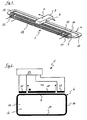
- Fig. 1 shows a displacement sensor system with a sensor 2 and a magnet 4, which is a permanent magnet.
- the sensor 2 has a core 6.
- This core 6 is in the form of a rectangular frame having two straight core sections 8 and 10 aligned parallel to one another and connected at their axial ends by means of straight core sections 12 and 14 which are significantly shorter than the core sections 8 and 10 and normal to the core sections 8 and 10 extend.
- the core sections 8 and 10 may also be shorter, so that, for example, a rather square core is formed.
- the core 6 encloses an open space 16.
- the core 6, as well as in the FIGS. 6 and 8th shown cores 6 'and the core 6 "in Fig. 10 may consist of an amorphous, nanocrystalline and / or crystalline ferromagnetic material.
- a primary coil 18 is arranged.
- a secondary coil 20 On the outside of a first end of the primary coil 18 is a secondary coil 20 and on the outside of a second end of the primary coil 18, a second secondary coil 22 is arranged.
- the coils can be wound conventionally or, as described below, be designed in planar technology.
- the core 6 is preferably formed in two parts.
- the core 6 consists of a first part, which is formed by a core portion, and a second part, which is formed by the remaining core portions.
- This embodiment of the core 6 facilitates the winding of the primary coil 18 and the secondary coils 20 and 22 on the core 6 or allows the primary coil 18 and the secondary coils 20 and 22 pre-wound réellestecken on the core 6. Subsequently, the two core parts are connected to the complete core 6, for example by soldering or welding. As from the diagram of the Fig. 2 shows, the primary coil 18 is connected to an AC voltage source, while the secondary coils 20 and 22 are each signal-connected to an evaluation device 24.
- the magnet 4 Spaced apart from the core 6 and spaced from the primary coil 18 wound around the core 6, the magnet 4 is arranged to be movable parallel to the core section 8 in a direction A and a direction B opposite thereto.
- the two poles of the magnet 4 are aligned in the direction of the longitudinal extent of the core portion 8.
- the magnet 4 is motion-coupled with a component, not shown, whose movement path or position is to be determined.
- the primary coil 18 forms a measuring path, as will be explained in detail below.
- the movement-coupled with the magnet 4 component can be arranged in a closed housing, wherein the sensor 2 is arranged outside of this housing. That a wall is located between the magnet 4 and the sensor 2.
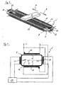
- That in the 3 and 4 illustrated displacement sensor system differs from that in the Fig. 1 and 2 shown way sensor system in that the secondary coils 20 and 22 are not arranged on the core section 8 but on the core sections 12 and 14 of the core 6 adjoining at right angles thereto at an angle. That is, on the core portion 8, only the primary coil 18 is arranged, which allows the core portions 8 and 10 relative to the in the Fig. 1 and 2 illustrated embodiment significantly shorter to dimension.
- a further primary coil 26 is provided which corresponds to the primary coil 18 and the primary coil 18 is arranged symmetrically to a central axis C on the core portion 10 opposite.
- the magnet 4 Spaced from the core 6, the magnet 4 is movable parallel to the core portions 8 and 10 above the primary coils 18 and 26. At this time, the magnet 4 generates saturation in both the core portion 8 and the core portion 10, whereby the primary coils 18 and 26 are respectively divided into two virtual sub-coils.
- the primary coils 18 and 26 are connected to generate a circulating magnetic flux in the core 6.
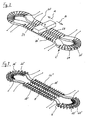
- the core 6 '( Fig. 6 and 8th ) two spaced apart and parallel to each other aligned straight core sections 8 'and 10'.
- the core sections 8 'and 10' are connected by means of core sections 12 'and 14'.
- the core portions 12 'and 14' are annular segment-shaped, wherein the outer diameter of the core portions 12 'and 14' is chosen so large that the core 6 'in the region of the core portions 8' and 10 'tapers like a bottle neck.
- the core 6 ' is completely surrounded by a non-conductive insulating sheath 28 ( Fig. 5 and 7 ).
- This Isolierummantelung 28 may eg by means Injection molding or other suitable method of MID technology or printed circuit board technology on the core 6 'are applied ( Fig. 5 and 7 ).
- the core 6 ' is completely arranged in printed circuit board technology between at least two flat substrate layers, which form an insulating sheath 28 of the core 6.
- the outer contour of the substrate halves is adapted to the outer contour of the core.
- the conductor track sections 30 are aligned substantially transversely to the longitudinal extent of these core sections 8 'and 10', while in the area in which later the core sections 12 'and 14 'are arranged, are substantially radially aligned.
- the conductor track sections 30 do not extend over the entire width of the surfaces of the insulating jacket 28 but each end at a distance from the longitudinal edges thereof. At all ends of the conductor track sections 30, bores 32 extend perpendicular to the surfaces of the insulating jacket 28 on the outside of the future arrangement of the core 6 'through the substrate halves.
- the holes 32 are formed as electrically conductive via holes 32. In this way, the conductor track sections 30 together with the holes 32 complete turns and thus in the region of the core portion 8 ', a primary coil 18', in the region of the core portion 10 'a primary coil 26', in the region of the core portion 12 ', a secondary coil 20' and in Area of the core portion 14 'a secondary coil 22' ( Fig. 6 ).
- the insulating sheath 28 does not have to correspond to the shape of the core 6 ', but rather the core 6' can also be embedded in an eg rectangular printed circuit board as insulating sheathing 28.
- FIGS. 7 and 8 illustrated embodiment are on two opposite surfaces of the here by means of injection-molded core 6 'in each case in the region of the core portions 8', 10 '12' and 14 'parallel to each other electrically conductive trace portions 30' on the Isolierummantelung 28 applied.
- the insulating sheath 28 could instead be assembled in injection molding as a circuit board of several layers.
- FIGS. 9 and 10 illustrated embodiment differs from that in the Fig. 6 and 8th
- the core 6 has two parallel straight straight core sections 8" and 10 ", which at their axial ends by means of semi-circularly curved core sections 12 "and 14" are connected.
- sensors 2 thus increase in the in Fig. 9 shown sensor 2 'in the region of the core portions 12 "and 14", the dimensions not transverse to the longitudinal extent of the sensor 2'.
- the core 6 "of the sensor 2 is surrounded by injection molding with an insulating jacket 28.
- a primary coil 18" is disposed around the core portion 8 "and a primary coil 26" is disposed around the core portion 10 "
- the secondary coil 20 "' has a coil section 40, which is arranged around the core section 8" on the outside of the primary coil 18 "'.
- This coil section 40 is conductively connected to a second coil section 42, which is arranged around the core section 10 "on the outside of the primary coil 26"'.
- the secondary coil 22 "' has a coil portion 44 disposed around the core portion 8" on the outside of the primary coil 18 ", which coil portion 44 is line connected to a second coil portion 46 surrounding the core portion 10" on the outside of the primary coil
- the primary coils 18 "'and 26"' as well as the secondary coils 20 “'and 22”' are provided by trace portions 30 "applied to two opposite surfaces of the insulating jacket 28 and trace portions 34 '. on the outside of the perpendicular to the surfaces aligned transverse sides the insulating jacket 28 are applied formed.
- a wiring portion 48 connecting the coil portions 40 and 42, while the coil portions 44 and 46 of the secondary coil 22"' are connected by a conductor beam portion 50.
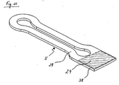
- Fig. 11 shows a provided with an insulating sheath 28 core 6 'of a sensor 2' of the displacement sensor system, which has been omitted for reasons of clarity on a representation of the tracks on the insulating sheath 28. These can be as described above on the basis of Fig. 5 to 8 be described described.
- the insulating sheath forms an extension 38 extending in the longitudinal extent of the sensor 2', on the surface of which, flat side, an electronic evaluation device 24 of the sensor 2 'is arranged.
Landscapes
- Physics & Mathematics (AREA)
- General Physics & Mathematics (AREA)
- Measurement Of Length, Angles, Or The Like Using Electric Or Magnetic Means (AREA)
- Transmission And Conversion Of Sensor Element Output (AREA)
Claims (9)
- Système de capteur de déplacement magnétique comprenant au moins un aimant (4) et au moins un capteur (2, 2') disposés de manière à pouvoir se déplacer l'un par rapport à l'autre, dans lequel le capteur (2, 2') présente un noyau magnétique doux (6, 6', 6") entourant une surface intérieure libre (16), caractérisé en ce que deux bobines primaires (18, 18', 18", 18"', 26, 26', 26", 26"') et deux bobines secondaires (20, 20', 20", 20"', 22, 22', 22", 22"') sont disposées sur le noyau (6, 6', 6"), l'aimant (4) étant disposé à l'extérieur de la surface définie par le noyau (6, 6', 6") et étant conçu pour produire une saturation magnétique dans le noyau (6, 6', 6"), et le noyau (6, 6', 6") présentant deux parties de noyau linéaires (8, 8', 8", 10, 10', 10") parallèles entre elles, qui sont reliées, à leurs extrémités axiales, respectivement à une partie de noyau (12, 12', 12", 14, 14', 14") s'y raccordant transversalement ou de manière arquée, et une bobine secondaire (20, 20', 20", 20"', 22, 22', 22", 22"') étant disposée sur chacune des deux parties de noyau (12, 12', 12", 14, 14', 14") se raccordant transversalement ou de manière arquée.
- Système de capteur de déplacement magnétique selon la revendication 1, dans lequel le noyau (6) forme un cadre sensiblement rectangulaire.
- Système de capteur de déplacement magnétique selon l'une des revendications précédentes, dans lequel les première (18, 18', 18", 18"') et deuxième (26, 26', 26", 26"') bobines primaires sont disposées sur deux parties de noyau (8, 8', 8", 10, 10', 10") situées en regard l'une de l'autre.
- Système de capteur de déplacement magnétique selon l'une des revendications précédentes, dans lequel les bobines primaires (18', 18", 18"', 26', 26", 26"') et/ou les bobines secondaires (20', 22", 22"') sont constituées de pistes conductrices (30, 30', 30") reliées entre elles.
- Système de capteur de déplacement magnétique selon la revendication 4, dans lequel les pistes conductrices (30) sont reliées entre elles au moyen de vias d'interconnexion.
- Système de capteur de déplacement magnétique selon la revendication 4, dans lequel les pistes conductrices (30', 30") sont reliées entre elles au moyen de jonctions latérales (34, 34').
- Système de capteur de déplacement magnétique selon l'une des revendications 4 à 6, dans lequel le noyau (6, 6', 6") présente une gaine isolante (28).
- Système de capteur de déplacement magnétique selon la revendication 7, dans lequel un dispositif d'évaluation (24) destiné à déterminer la position de l'aimant (4) est disposé sur la gaine isolante (28).
- Système de capteur de déplacement magnétique selon l'une des revendications précédentes, dans lequel l'aimant (4) et le capteur (2, 2') sont disposés sur des faces opposées d'une paroi.
Priority Applications (1)
| Application Number | Priority Date | Filing Date | Title |
|---|---|---|---|
| EP20080013718 EP2149784B1 (fr) | 2008-07-31 | 2008-07-31 | Système de capteur de trajectoire magnétique |
Applications Claiming Priority (1)
| Application Number | Priority Date | Filing Date | Title |
|---|---|---|---|
| EP20080013718 EP2149784B1 (fr) | 2008-07-31 | 2008-07-31 | Système de capteur de trajectoire magnétique |
Publications (2)
| Publication Number | Publication Date |
|---|---|
| EP2149784A1 EP2149784A1 (fr) | 2010-02-03 |
| EP2149784B1 true EP2149784B1 (fr) | 2012-04-04 |
Family
ID=40134865
Family Applications (1)
| Application Number | Title | Priority Date | Filing Date |
|---|---|---|---|
| EP20080013718 Ceased EP2149784B1 (fr) | 2008-07-31 | 2008-07-31 | Système de capteur de trajectoire magnétique |
Country Status (1)
| Country | Link |
|---|---|
| EP (1) | EP2149784B1 (fr) |
Cited By (2)
| Publication number | Priority date | Publication date | Assignee | Title |
|---|---|---|---|---|
| CN105008862A (zh) * | 2013-03-01 | 2015-10-28 | 大陆-特韦斯贸易合伙股份公司及两合公司 | 用于检测发生器磁体的位置的传感器 |
| WO2020104656A1 (fr) | 2018-11-22 | 2020-05-28 | Vitesco Technologies Germany Gmbh | Système de capteur de positionnement magnétique et module de capteur |
Families Citing this family (5)
| Publication number | Priority date | Publication date | Assignee | Title |
|---|---|---|---|---|
| DE102012005344B4 (de) * | 2012-03-16 | 2014-12-18 | Tyco Electronics Amp Gmbh | Berührungsloser weggeber nach dem plcd-prinzip |
| DE102012215862B4 (de) * | 2012-09-06 | 2022-10-06 | Deutsches Zentrum für Luft- und Raumfahrt e.V. | Oberflächenmontierbare Drossel |
| CN104956187B (zh) | 2013-02-01 | 2017-06-09 | 大陆-特韦斯贸易合伙股份公司及两合公司 | 用于制造传感元件的方法 |
| US9577185B1 (en) * | 2016-04-28 | 2017-02-21 | Texas Instruments Incorporated | Fluxgate device with low fluxgate noise |
| US11333529B2 (en) | 2018-05-22 | 2022-05-17 | Swoboda Schorndorf KG | Magnetic position sensor |
Family Cites Families (19)
| Publication number | Priority date | Publication date | Assignee | Title |
|---|---|---|---|---|
| US3480854A (en) * | 1964-11-09 | 1969-11-25 | Sybron Corp | Movable magnet magnetic flux transducers and transduction systems for indicating magnet position |
| GB1347329A (en) * | 1971-01-27 | 1974-02-27 | Westinghouse Electric Corp | Magnetic position indicator |
| DE2415232A1 (de) * | 1974-03-29 | 1975-10-02 | Philips Patentverwaltung | Elektromagnetischer weggeber |
| US4380928A (en) * | 1980-08-29 | 1983-04-26 | Aisin Seiki Company, Limited | Rotational angle sensor |
| DE3610479A1 (de) | 1986-03-27 | 1987-10-01 | Vacuumschmelze Gmbh | Magnetischer wegsensor |
| DE4425904A1 (de) | 1994-07-21 | 1996-01-25 | Vacuumschmelze Gmbh | Magnetischer Wegsensor |
| DE4425903C2 (de) | 1994-07-21 | 1997-03-20 | Siemens Ag | Vorrichtung mit einem Meßtransformator zur Erfassung der Position eines linear beweglichen Objektes |
| DE69837694T2 (de) * | 1997-05-21 | 2008-01-10 | Sony Manufacturing Systems Corp., Kuki | Fühler für magnetisches Metall und Verfahren zum Detektieren eines magnetischen Metalls |
| DE19805783C2 (de) * | 1998-02-12 | 2000-06-08 | Siemens Ag | Anordnung zur zweidimensionalen, berührungslosen Positionsbestimmung eines Meßobjektes |
| DE19805621A1 (de) * | 1998-02-12 | 1999-08-19 | Hydraulik Ring Gmbh | Anordnung zur berührungslosen Positionsbestimmung eines Meßobjektes, vorzugsweise einer Schaltwelle eines Kraftfahrzeuggetriebes |
| DE19919424A1 (de) | 1999-04-28 | 2000-11-30 | Tyco Electronics Logistics Ag | Magnetischer Positionssensor, seine Verwendung und seine Herstellung |
| DE10139707A1 (de) * | 2001-08-11 | 2003-02-20 | Philips Corp Intellectual Pty | Leiterplatte |
| KR100432661B1 (ko) * | 2002-03-09 | 2004-05-22 | 삼성전기주식회사 | 인쇄회로기판 기술을 이용한 미약자계 감지용 센서 및 그제조방법 |
| DE10354694C5 (de) * | 2003-11-22 | 2008-10-09 | Sick Ag | Induktiver Sensor |
| DE102004004100B4 (de) * | 2004-01-27 | 2007-02-01 | Siemens Ag | Positionssensor und entsprechendes Verfahren zum Detektieren der Position eines Rotationskörpers |
| DE102004016622B4 (de) * | 2004-04-03 | 2008-11-27 | Festo Ag & Co. Kg | Positionssensoranordnung |
| KR100619368B1 (ko) * | 2004-07-05 | 2006-09-08 | 삼성전기주식회사 | 미약자계 감지용 센서를 구비한 인쇄회로기판 및 그 제작방법 |
| KR100619369B1 (ko) * | 2004-07-24 | 2006-09-08 | 삼성전기주식회사 | 미약자계 감지용 센서를 구비한 인쇄회로기판 및 그 제작방법 |
| FR2873807B1 (fr) | 2004-07-27 | 2007-04-27 | Electricfil Automotive Soc Par | Capteur magnetique de position sans contact |
-
2008
- 2008-07-31 EP EP20080013718 patent/EP2149784B1/fr not_active Ceased
Cited By (2)
| Publication number | Priority date | Publication date | Assignee | Title |
|---|---|---|---|---|
| CN105008862A (zh) * | 2013-03-01 | 2015-10-28 | 大陆-特韦斯贸易合伙股份公司及两合公司 | 用于检测发生器磁体的位置的传感器 |
| WO2020104656A1 (fr) | 2018-11-22 | 2020-05-28 | Vitesco Technologies Germany Gmbh | Système de capteur de positionnement magnétique et module de capteur |
Also Published As
| Publication number | Publication date |
|---|---|
| EP2149784A1 (fr) | 2010-02-03 |
Similar Documents
| Publication | Publication Date | Title |
|---|---|---|
| WO2018177580A1 (fr) | Ensemble de poignée de porte pour véhicule automobile muni d'un capteur capacitif et d'un système de communication en champ proche | |
| EP2037286A1 (fr) | Dispositif de mesure destiné à la mesure d'un champ magnétique | |
| EP0557608A1 (fr) | Assemblage de bobines | |
| EP2149784A1 (fr) | Système de capteur de trajectoire magnétique | |
| EP3417245B1 (fr) | Capteur | |
| DE102008037893B4 (de) | Induktiver Leitungsfähigkeitssensor | |
| EP0814321B1 (fr) | Capteur inductif de déplacement | |
| EP2302328B1 (fr) | Couplage d'aimant permanent avec un sensemble de bobines émettrices qui se croisent plusieurs fois | |
| DE10354694B4 (de) | Induktiver Sensor | |
| EP2946174A1 (fr) | Arrangement de bobines comportant deux bobines | |
| DE10220983B4 (de) | Sensor für schwach magnetische Felder unter Verwendung der Herstellungstechnik für gedruckte Leiterplatten und Verfahren zum Herstellen eines solchen Sensors | |
| EP3245480B1 (fr) | Détermination inductive de position | |
| DE102016216330A1 (de) | Flexible Spulenordnung für einen magnetoelektrischen Weggeber, Weggeber und Herstellungsverfahren | |
| WO2021249776A1 (fr) | Capteur inductif de position | |
| EP3417244B1 (fr) | Capteur | |
| EP0797078A1 (fr) | Capteur inductif pour mesurer l'angle de rotation | |
| DE102011010682B3 (de) | Spulenanordnung und Sensor | |
| DE102020119985A1 (de) | Positionssensor zum Bestimmen der Position einer Ventilstange eines Stellventils | |
| EP3884240B1 (fr) | Système de capteur de positionnement magnétique et module de capteur | |
| DE102018222569A1 (de) | Messeinrichtung zur Bestimmung einer Weg- und/oder Winkeländerung zwischen der Messeinrichtung und einem gegenüberliegenden Positionselement und Messverfahren | |
| DE102017222248A1 (de) | Drossel mit Stromsensor | |
| EP3557188B1 (fr) | Bielle magnétisée destinée à la mesure de course | |
| DE102019132963B4 (de) | Strommessanordnung | |
| DE102009058835A1 (de) | Sensorspule | |
| DE102008011971A1 (de) | Magnetisches Wegsensorsystem |
Legal Events
| Date | Code | Title | Description |
|---|---|---|---|
| PUAI | Public reference made under article 153(3) epc to a published international application that has entered the european phase |
Free format text: ORIGINAL CODE: 0009012 |
|
| AK | Designated contracting states |
Kind code of ref document: A1 Designated state(s): AT BE BG CH CY CZ DE DK EE ES FI FR GB GR HR HU IE IS IT LI LT LU LV MC MT NL NO PL PT RO SE SI SK TR |
|
| AX | Request for extension of the european patent |
Extension state: AL BA MK RS |
|
| 17P | Request for examination filed |
Effective date: 20100802 |
|
| 17Q | First examination report despatched |
Effective date: 20100827 |
|
| AKX | Designation fees paid |
Designated state(s): DE |
|
| GRAP | Despatch of communication of intention to grant a patent |
Free format text: ORIGINAL CODE: EPIDOSNIGR1 |
|
| GRAS | Grant fee paid |
Free format text: ORIGINAL CODE: EPIDOSNIGR3 |
|
| GRAA | (expected) grant |
Free format text: ORIGINAL CODE: 0009210 |
|
| AK | Designated contracting states |
Kind code of ref document: B1 Designated state(s): DE |
|
| REG | Reference to a national code |
Ref country code: DE Ref legal event code: R096 Ref document number: 502008006842 Country of ref document: DE Effective date: 20120531 |
|
| PLBE | No opposition filed within time limit |
Free format text: ORIGINAL CODE: 0009261 |
|
| STAA | Information on the status of an ep patent application or granted ep patent |
Free format text: STATUS: NO OPPOSITION FILED WITHIN TIME LIMIT |
|
| 26N | No opposition filed |
Effective date: 20130107 |
|
| REG | Reference to a national code |
Ref country code: DE Ref legal event code: R097 Ref document number: 502008006842 Country of ref document: DE Effective date: 20130107 |
|
| PGFP | Annual fee paid to national office [announced via postgrant information from national office to epo] |
Ref country code: DE Payment date: 20180705 Year of fee payment: 11 |
|
| REG | Reference to a national code |
Ref country code: DE Ref legal event code: R119 Ref document number: 502008006842 Country of ref document: DE |
|
| PG25 | Lapsed in a contracting state [announced via postgrant information from national office to epo] |
Ref country code: DE Free format text: LAPSE BECAUSE OF NON-PAYMENT OF DUE FEES Effective date: 20200201 |