EP2149797B1 - Procédé et dispositif de mesure d'un angle selon lequel un champ magnétique est agencé dans un plan par rapport à un axe de référence - Google Patents
Procédé et dispositif de mesure d'un angle selon lequel un champ magnétique est agencé dans un plan par rapport à un axe de référence Download PDFInfo
- Publication number
- EP2149797B1 EP2149797B1 EP08013832A EP08013832A EP2149797B1 EP 2149797 B1 EP2149797 B1 EP 2149797B1 EP 08013832 A EP08013832 A EP 08013832A EP 08013832 A EP08013832 A EP 08013832A EP 2149797 B1 EP2149797 B1 EP 2149797B1
- Authority
- EP
- European Patent Office
- Prior art keywords
- magnetic field
- signal
- phase
- input
- oscillator
- Prior art date
- Legal status (The legal status is an assumption and is not a legal conclusion. Google has not performed a legal analysis and makes no representation as to the accuracy of the status listed.)
- Active
Links
Images
Classifications
-
- G—PHYSICS
- G01—MEASURING; TESTING
- G01R—MEASURING ELECTRIC VARIABLES; MEASURING MAGNETIC VARIABLES
- G01R33/00—Arrangements or instruments for measuring magnetic variables
- G01R33/0023—Electronic aspects, e.g. circuits for stimulation, evaluation, control; Treating the measured signals; calibration
- G01R33/0029—Treating the measured signals, e.g. removing offset or noise
-
- G—PHYSICS
- G01—MEASURING; TESTING
- G01R—MEASURING ELECTRIC VARIABLES; MEASURING MAGNETIC VARIABLES
- G01R33/00—Arrangements or instruments for measuring magnetic variables
- G01R33/02—Measuring direction or magnitude of magnetic fields or magnetic flux
- G01R33/028—Electrodynamic magnetometers
- G01R33/0283—Electrodynamic magnetometers in which a current or voltage is generated due to relative movement of conductor and magnetic field
-
- G—PHYSICS
- G01—MEASURING; TESTING
- G01R—MEASURING ELECTRIC VARIABLES; MEASURING MAGNETIC VARIABLES
- G01R33/00—Arrangements or instruments for measuring magnetic variables
- G01R33/02—Measuring direction or magnitude of magnetic fields or magnetic flux
- G01R33/06—Measuring direction or magnitude of magnetic fields or magnetic flux using galvano-magnetic devices
- G01R33/07—Hall effect devices
- G01R33/072—Constructional adaptation of the sensor to specific applications
- G01R33/075—Hall devices configured for spinning current measurements
Definitions
- the invention relates to a device for measuring an angle, under which a magnetic field is arranged in a plane relative to a reference axis, with at least two magnetic field sensors, which are arranged with their measuring axes in and / or parallel to the plane and oriented transversely to each other. Furthermore, the invention relates to a method for measuring an angle at which a magnetic field is arranged in a plane relative to a reference axis, wherein a first magnetic field component and a second magnetic field component arranged transversely thereto are measured in and / or parallel to the plane.
- a device of the aforementioned type which has a semiconductor substrate, in which 64 so-called vertical Hall sensors are integrated as magnetic field sensors.
- the magnetic field sensors are arranged at equal distances from one another on a circular ring lying in the chip plane of the semiconductor substrate such that the planes in which the magnetic field sensors extend are each arranged radially to an imaginary central axis which runs through the center of the circular ring and orthogonal to the chip plane is arranged.
- the magnetic field sensors are connected to a scanning device in such a way that the measuring signals of the individual magnetic field sensors can be applied successively to a differential output connection for a rotation scanning signal.
- the magnetic field sensors are thus cyclically read one after the other in rotation.
- the differential output terminal is connected via a differential amplifier to a low-pass integrated in the semiconductor substrate. With the help of the low-pass filter, the analog output signal of the amplifier is smoothed to an approximately sinusoidal signal. The zero crossing of the analog measurement signal thus obtained is determined and from the zero crossing point, the angle at which a magnetic field flowing through the semiconductor substrate is arranged in the chip plane relative to a reference axis is determined.
- the device has the disadvantage that the reading out of the many magnetic field sensors is time-consuming. Therefore, despite the high circuit complexity, the device allows only a small bandwidth.
- Another disadvantage is that the non-negative feedback, analogue low-pass has to meet high requirements in terms of linearity and frequency response, which means a high area consumption on the semiconductor chip and a high power consumption.
- a device of the aforementioned type which has two magnetic field sensors integrated in a semiconductor chip magnetoresistive sensors, which are arranged with their measuring axes in a plane perpendicular to each other.
- Each magnetic field sensor is in each case connected to an analog-to-digital converter, which is designed as a sigma-delta modulator.
- Each analog-to-digital converter is followed by a decimation filter, at the output of which a magnetic field measured value in the form of a 15-bit digital word is output.
- the digital words are transmitted to an arithmetic unit which calculates the angle at which a magnetic field passing through the semiconductor substrate in the chip plane relative to a reference axis is calculated from the arctangent of the quotient of the digital words.
- the relatively large circuit complexity is disadvantageous.
- By calculating the magnetic field angle results in a latency, which is disadvantageous when using the device in a control loop.
- the object is to provide a device of the type mentioned, which allows a simple structure and high accuracy.
- the object is to provide a method of the type mentioned above, with which the angle can be determined in a simple manner with great precision.
- the object is achieved in that the device comprises a PLL phase-locked loop with a phase-locked loop arranged in the follower oscillator, that the tracking oscillator has at least one oscillator output for a digital vibration signal that the magnetic field sensors are coupled to the phase-locked loop, that the digital vibration signal phase-synchronous to a by rotating the measuring signals of the Magnetic field sensors formed Rotationsabtastsignai, and that the oscillator output is connected to determine the phase position of the digital vibration signal with a phase position detector.
- the device thus has a simply constructed, cost-producible phase-locked loop (PLL) phase-locked loop, which is synchronous with respect to the phase of its digital oscillation signal to the phase of a Rotationsabtastsignals formed by rotating read the Meßsignalaus réelle the magnetic field sensors.
- PLL phase-locked loop
- synchronous is understood to mean that the phase position of the digital vibration signal is identical or shifted by a known, constant angle with that of the rotation scanning signal.
- the angle at which the magnetic field is arranged in the plane defined by the axes of the magnetic field sensors relative to the reference axis can be determined in a simple manner by determining the phase angle of the digital vibration signal.
- the magnetic field sensors are connected to a scanning device in such a way that the measuring signals of the individual magnetic field sensors can be applied successively to an output terminal for the rotational scanning signal, and if the output terminal is connected to a synchronization signal input of the PLL phase locked loop.
- the scanning device can be connected downstream of the measuring signal terminals of the magnetic field sensors.
- the magnetic field sensors or circuit parts thereof are switched on and off by means of the scanning device in order to activate or deactivate the corresponding magnetic field sensor.
- each magnetic field sensor has in each case one measuring signal output connected to an input connection of a multiplexer, wherein the multiplexer has an output which can be connected to the individual input connections and forms the output connection for the rotation scanning signal.
- the output terminal for the Rotationsabtastsignal is connected to a first input of a frequency mixer and the oscillator output of the tracking oscillator to a second input of the frequency mixer, wherein a mixer output of the frequency mixer is connected via at least one low-pass filter and at least one clocked comparator to a frequency control input of the tracking oscillator.
- a mixer output of the frequency mixer is connected via at least one low-pass filter and at least one clocked comparator to a frequency control input of the tracking oscillator.
- an analog signal for difference frequency between the rotational frequency of Rotationsabtastsignals and that of the digital vibration signal is generated with the aid of the frequency mixer and the low-pass filter connected downstream. This is then converted by means of the comparator into a digital control signal for the tracking oscillator.
- the analog low-pass filter of the phase-locked loop enables a high loop gain in the signal band of the angle change with simultaneously low loop gain at the rotational frequency, so that a spectral shift of the quantization noise takes place from the signal band, the so-called noise shaping.
- the order and the frequency response of the low-pass filter can be adapted to the conditions of the application, as with any sigma-delta modulator.
- the phase position detector has a quadrant detector which has a first polarity detector and a second polarization detector, an input of the first polarization detector is connected to a measurement signal output of a first magnetic field sensor and an input of the second polarization detector is connected to a measurement signal output of a second magnetic field sensor, and if second magnetic field sensor is arranged with its measuring axis orthogonal to the measuring axis of the first magnetic field sensor. This makes it possible to unambiguously assign the measured magnetic field angle to a quadrant and thus to determine the magnitude and the sign of the angle.
- the magnetic field sensors are Hall sensors which have a switching device for orthogonal switching of the Hall sensor supply current and the Hall voltage taps, wherein the switching device has a clock input connected to a clock input for a switching clock signal.
- the invention can therefore also be combined with the so-called spinning current technique.
- the clock frequency of the switching clock signal of at least one magnetic field sensor is selected such that within a sampling cycle during which the measuring signal of this magnetic field sensor with the phase-locked loop is coupled, the switching means for orthogonal switching occupies at least two and preferably four different switching states.
- the clock frequency of the switching clock signal of at least one magnetic field sensor is selected such that the Hall sensor supply current of the magnetic field sensor after each rotational revolution of the Rotationsabtastsignals once changed its direction.
- a spin cycle is then completed after four rotation cycles of the rotation scan signal.
- a decimation filter can suppress these frequency components, so that the averaging of the sensor offsets is possible without additional effort.
- the comparator has a clock signal input connected to a clock signal generator, wherein the clock signal generator is configured such that the clock frequency of a voltage applied to the clock signal input comparator clock signal is at least twice as large as the rotational frequency of Rotationsabtastsignals.
- the follower oscillator has a number of oscillating outputs for mutually phase-shifted digital vibration signals, wherein in the phase locked loop one of said number corresponding frequency mixer are arranged, wherein each frequency mixer each one with a Measuring signal output of the frequency mixer associated magnetic field sensor connected to the first input and a second input connected to one of the oscillator outputs, and wherein the mixer outputs of the frequency mixer via a Adder, at least one low-pass filter and at least one clocked comparator are connected to the frequency control input of the tracking oscillator.
- the Abtstrate of the comparator preferably has four times the frequency of rotation circulation. As a result, the magnetic field angle can be measured even faster.
- the measuring accuracy of the device can also be increased by providing a plurality of mutually parallel magnetic field sensors for each measuring axis, and averaging the measuring signals of these magnetic field sensors.
- the above-mentioned object is achieved in that at least one digital oscillation signal is generated, that the phase position of the digital oscillation signal is controlled so that it is phase-synchronized to the phase position of a Rotationsabtastsignals formed by rotating scanning of the measuring signals of the magnetic field sensors, and that angle is determined from the phase angle of the digital oscillation signal.
- this makes it possible to determine the angle at which the magnetic field is arranged in the plane defined by the axes of the magnetic field sensors relative to the reference axis in a simple manner by determining the phase angle of the digital vibration signal.
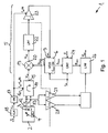
- a generally designated 1 device for measuring an angle at which a magnetic field B is arranged in a plane 2 relative to a reference axis has two designed as Hall sensors magnetic field sensors 3, 4, which are arranged with their measuring axes orthogonal to each other.
- a first magnetic field sensor 3 is sensitive to an x component of the magnetic field B and a second magnetic field sensor 4 is sensitive to a y component of the magnetic field B.
- the magnetic field sensors 3, 4 are integrated in a semiconductor chip not shown in detail in the drawing. They each have a monolithically integrated in a semiconductor substrate Hall plate, which is arranged with its plane of extension perpendicular to the plane of the semiconductor chip.
- the device 1 comprises a PLL phase locked loop 5 with one in a phase locked loop in which a tracking oscillator 6 is arranged.
- the tracking oscillator 6 has in the embodiment according to Fig. 1 an oscillator output 7 for an approximately rectangular digital oscillation signal 8.
- the trailing oscillator 6 has a frequency control input 9.
- the fundamental frequency of the digital oscillation signal 8 is dependent on a voltage applied to the frequency control input 9 voltage.
- the magnetic field sensors 3, 4 are coupled to the phase-locked loop in such a way that the digital oscillation signal is in phase synchronization with a rotational scanning signal 10 formed by rotating scanning of the measurement signals of the magnetic field sensors 3, 4.
- the sampling values sampled in the rotation scanning signal 10 and sampled by the measuring signal of the first magnetic field sensor 3 are denoted respectively by X + and X- and the sampled values sampled by the measuring signal of the second magnetic field sensor 4 are respectively denoted Y + and Y-.
- Y + and Y- the sampled values sampled by the measuring signal of the second magnetic field sensor 4
- the measurement signal outputs 12, 13 of the magnetic field sensors 3, 4 are each connected to an input terminal of a multiplexer 14. With the aid of the multiplexer 14, the measuring signal outputs 12, 13 are each cyclically connected in succession to an output terminal 15 for the rotation scanning signal 10 provided at the multiplexer 14.
- the multiplexer 14 has a control input 16 to which a rotation clock signal is applied.
- the rotation clock signal is formed by means of a frequency divider 17 from a system clock of a clock signal generator 18.
- the frequency of the rotation clock signal is in Fig. 1 with f red and the frequency of the system clock is denoted by f clk .
- the division ratio N of the frequency divider 17 corresponds to the number of clock pulses that a rotation cycle lasts.
- the output terminal 15 for the Rotationsabtastsignal 10 is connected to a serving as Synchronisafionssignaleingang for the phase locked loop 5 first input of a frequency mixer 19 and the oscillator output 7 of the tracking oscillator 6 to a second input of the frequency mixer 19.
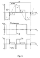
- a mixer output 20 of the frequency mixer 19 is a mixed signal 21, which corresponds to the product of the Rotationsabtastsignal V red and the digital vibration signal 8 ( Fig. 3 ).
- the mixer output 20 of the frequency mixer 19 is connected via an analog low-pass filter 22 to an input of a comparator 23 clocked with the rotation clock signal.
- the comparator evaluates the analogue filtered signal after every rotation rotation. Its resolution can be 1 bit in the simplest case.
- At the output of the comparator 23 is applied to a digital signal which is supplied to the frequency control input 9 of the tracking oscillator 6 to form a control loop.
- Fig. 3 It can be seen that the digital oscillation signal 8 is phase-locked with the phase-locked loop locked to the rotational scanning signal 10 or to the sinusoidal curve shown in dashed lines. Due to the special properties of the tracking oscillator results in a phase offset of about 90 ° between the digital oscillation signal 8 and the Rotationsabtastsignal 10.
- the device 1 has a phase position detector. This has a counter 24 for the clock pulses of the system clock.
- the counter 24 is started by a start pulse marking a virtual zero phase position 25 corresponding to the reference axis for the angle measurement.
- the counter 24 stops as soon as a flank or a zero crossing occurs in the digital oscillation signal.
- At the output of the counter 24 there is a digital signal ⁇ vco corresponding to the phase angle of the digital oscillation signal 8.
- the output of the counter 24 is connected to a first input of a low-pass filter 26.
- the phase position detector further comprises a quadrant detector having a first polarity detector 27 and a second polarization detector 28.
- An input of the first polarization detector 27 is connected to the measurement signal output 12 of the first magnetic field sensor 3 and an input of the second polarization detector 28 is connected to the measurement signal output 1 3 of a second magnetic field sensor 4.
- An output of the phase position detector is connected to a second input of the low-pass filter 26. At the output of the low-pass filter 26 there is a measurement signal ⁇ out corresponding to the angle of the magnetic field.
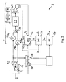
- the tracking oscillator 6 has oscillator outputs 7a, 7b for two digital oscillatory signals.
- a first digital oscillating signal is applied to a first oscillator output 7a and a second digital oscillating signal is applied to a second oscillator output 7b of the tracking oscillator 6 on.
- the first digital oscillation signal and the second digital oscillation signal are phase-shifted by 90 ° from each other (quadrature signals).
- Fig. 2 is also apparent that in the phase locked loop two frequency mixer 19a, 19b are arranged.
- a first input of a first frequency mixer 19a is connected to the measuring signal output 12 of the first magnetic field sensor 3 and a second input of the first frequency mixer 19a is connected to the first oscillator output 7a.
- the first input of a second frequency mixer 19b is connected to the measuring signal output 13 of the second magnetic field sensor 4 and a second input of the second frequency mixer 19b to the second oscillator output 7b.
- the in Fig. 1 provided multiplexer 14 and rotary switch so omitted in Fig. 2 ,
- the mixer outputs 20a, 20b of the frequency mixers 19a, 19b are each connected to an input of an adder 29.
- the output of the adder 29 is connected via an analog low-pass filter 22 to an input of a comparator 23 clocked with a clock signal.
- the frequency of the clock signal is four times the clock frequency f clk of the clock 18, divided by the number N of clock pulses, which takes a rotation cycle
- phase position detector in Fig. 2 corresponds to that of Fig. 1 , which is why in this respect reference is made to the description there.
Landscapes
- Physics & Mathematics (AREA)
- Condensed Matter Physics & Semiconductors (AREA)
- General Physics & Mathematics (AREA)
- Transmission And Conversion Of Sensor Element Output (AREA)
- Measuring Magnetic Variables (AREA)
Claims (11)
- Dispositif (1) de mesure d'un angle, selon lequel un champ magnétique (B) est agencé dans un plan (2) par rapport à un axe de référence, avec au moins deux capteurs de champ magnétique (2, 4), disposés avec leurs axes de mesure dans et/ou parallèlement au plan (2) et orientés perpendiculairement les uns par rapport aux autres, avec un circuit de régulation de phase PLL (5) comportant une boucle de régulation de phase,
caractérisé en ce que
la boucle de régulation de phase présente un mélangeur de fréquences (19) et un comparateur (23) cadencé, en circuit avec un oscillateur de poursuite (6), en ce que l'oscillateur de poursuite (6) présente au moins une sortie d'oscillateur (7), reliée au mélangeur de fréquences (19), pour un signal d'oscillation numérique (8), en ce que les capteurs de champ magnétique (3, 4) sont couplés au circuit de régulation de phase, de manière à ce que le signal d'oscillation numérique (8) soit en synchronisme de phase avec un signal d'exploration rotative (10) formé par exploration rotative des signaux de mesure des capteurs de champ magnétique (3, 4), et en ce que la sortie d'oscillateur (7) est reliée à un détecteur de position de phase, pour la détermination de la position de phase du signal d'oscillation numérique (8). - Dispositif (1) selon la revendication 1, caractérisé en ce que les capteurs de champ magnétique (3, 4) sont reliés à un dispositif d'exploration, de manière à ce que les signaux de mesure des différents capteurs de champ magnétique (3, 4) soient susceptibles d'être appliqués, les uns après les autres, à un raccordement de sortie (15) pour le signal d'exploration rotative (10), et en ce que le raccordement de sortie (15) est relié à une entrée de signal de synchronisation du circuit de régulation de phase PLL (5).
- Dispositif (1) selon la revendication 1 ou 2, caractérisé en ce que chaque capteur de champ magnétique (3, 4) présente respectivement une sortie de signal de mesure reliée à un raccordement d'entrée d'un multiplexeur (14), et en ce que le multiplexeur (14) présente une sortie, susceptible d'être reliée aux différents raccordements d'entrée, formant le raccordement de sortie (15) pour le signal d'exploration rotative (10).
- Dispositif (1) selon l'une des revendications 1 à 3, caractérisé en ce que le raccordement de sortie (15) pour le signal d'exploration rotative (10) est relié à une première entrée du mélangeur de fréquences (19), et la sortie d'oscillateur (7) de l'oscillateur de poursuite (6) est reliée à une deuxième entrée du mélangeur de fréquences (19), et en ce qu'une sortie de mélangeur (20) du mélangeur de fréquences (19) est raccordée, par l'intermédiaire d'au moins un filtre passe-bas (22) et du comparateur (23) cadencé, à une entrée de commande en fréquences (9) de l'oscillateur de poursuite (6).
- Dispositif (1) selon l'une des revendications 1 à 4, caractérisé en ce que le détecteur de position de phase présente un détecteur à quadrants, comprenant un premier détecteur de polarisation (27) et un deuxième détecteur de polarisation (28), en ce qu'une entrée du premier détecteur de polarisation (27) est reliée à une sortie de signal de mesure (12) d'un premier capteur de champ magnétique (3) et une entrée du deuxième détecteur de polarisation (28) est reliée à une sortie de signal de mesure (13) d'un deuxième capteur de champ magnétique (4), et en ce que le deuxième capteur de champ magnétique (4) est disposé avec son axe de mesure orienté perpendiculairement à l'axe de mesure du premier capteur de champ magnétique (3).
- Dispositif (1) selon l'une des revendications 1 à 5, caractérisé en ce que les capteurs de champ magnétique (3, 4) sont des capteurs à effet Hall, présentant un dispositif de commutation pour la commutation orthogonale du courant d'alimentation de capteur à effet Hall et des prélèvements de tension d'effet Hall, et en ce que le dispositif de commutation présente une entrée de cadencement, reliée à un générateur de cadencement, pour un signal de cadencement de commutation.
- Dispositif (1) selon l'une des revendications 1 à 6, caractérisé en ce que la fréquence de cadencement du signal de cadencement de commutation d'au moins un capteur de champ magnétique (3, 4) est choisie telle que, dans un cycle d'exploration, pendant lequel le signal de mesure de ce capteur de champ magnétique est couplé à la boucle de régulation de phase, le dispositif de commutation prend au moins deux et, de préférence, quatre états de commutation différents, par rapport à la commutation orthogonale.
- Dispositif (1) selon l'une des revendications 1 à 7, caractérisé en ce que la fréquence de cadencement du signal de cadencement de commutation d'au moins un capteur de champ magnétique (3, 4) est choisie telle que le courant d'alimentation du capteur à effet Hall du capteur de champ magnétique change une fois de sens après chaque rotation du signal d'exploration rotative (10).
- Dispositif (1) selon l'une des revendications 1 à 8, caractérisé en ce que le comparateur (23) présente une entrée de signal de cadencement reliée à un générateur de signal de cadencement, et en ce que le générateur de signal de cadencement est réalisé de manière à ce que la fréquence de cadencement d'un signal de cadencement de comparateur, appliqué à l'entrée de signal de cadencement, est d'au moins deux fois la valeur de la fréquence de rotation du signal d'exploration rotative (10).
- Dispositif (1) selon l'une des revendications 1 à 9, caractérisé en ce que l'oscillateur de poursuite (6) présente un nombre, correspondant au nombre des capteurs de champ magnétique (3, 4) disposés avec leurs axes de mesure perpendiculaires les uns aux autres, de sorties d'oscillateur (7a, 7b) pour des signaux d'oscillation numérique mutuellement déphasés, en ce qu'un nombre, correspondant au nombre cité, de mélangeurs de fréquences (19a, 19b) sont disposés dans la boucle de régulation de phase, en ce que chaque mélangeur de fréquences (19a, 19b) présente une première entrée, reliée à une sortie de signal de mesure (12, 13) d'un capteur de champ magnétique (3, 4) associé au mélangeur de fréquences (19a, 19b), et une deuxième entrée, reliée à l'une des sorties d'oscillateur (7a, 7b), et en ce que des sorties de mélangeur des mélangeurs de fréquences (19a, 19b) sont raccordées, par l'intermédiaire d'un organe additionneur (29), d'au moins un filtre passe-bas (22) et d'au moins un comparateur (23) cadencé, à l'entrée de commande en fréquence (9) de l'oscillateur de poursuite (6).
- Procédé de mesure d'un angle, selon lequel un champ magnétique (B) est agencé dans un plan (2) par rapport à un axe de référence, une première composante de champ magnétique (Vx) et une deuxième composante de champ magnétique (Vy), lui étant perpendiculaires sont mesurées dans et/ou parallèlement au plan (2), et la position de phase d'un signal d'oscillation numérique est régulée à l'aide d'un circuit de régulation de phase PLL (5), avec une boucle de régulation de phase,
caractérisé en ce que la boucle de régulation de phase présente un mélangeur de fréquences (19) et un comparateur (23) cadencé, branché avec un oscillateur de poursuite (6), et le signal d'oscillation numérique (8) est généré par l'oscillateur de poursuite (6), qui présente au moins une sortie d'oscillateur (7) reliée au mélangeur de fréquences (19), et en ce que
la position de phase du signal d'oscillation numérique (8) est régulée de manière à ce qu'elle soit en synchronisme de phase par rapport à la position de phase d'un signal d'exploration rotative (10) formé par exploration rotative des signaux de mesure des capteurs de champ magnétique (3, 4), et en ce que l'angle est déterminé à partir de la position de phase du signal d'oscillation numérique (8).
Priority Applications (4)
| Application Number | Priority Date | Filing Date | Title |
|---|---|---|---|
| EP08013832A EP2149797B1 (fr) | 2008-08-01 | 2008-08-01 | Procédé et dispositif de mesure d'un angle selon lequel un champ magnétique est agencé dans un plan par rapport à un axe de référence |
| JP2009172767A JP2010038915A (ja) | 2008-08-01 | 2009-07-24 | 平面内で磁場が基準軸に対して配置されている角度を測定する方法及び装置 |
| US12/533,350 US8125221B2 (en) | 2008-08-01 | 2009-07-31 | Method and device for measuring an angle at which a magnetic field is aligned in a plane relative to a reference axis |
| CN200910211636XA CN101685145B (zh) | 2008-08-01 | 2009-07-31 | 用于测量磁场相对于基准轴布置在一平面中的角度的方法和装置 |
Applications Claiming Priority (1)
| Application Number | Priority Date | Filing Date | Title |
|---|---|---|---|
| EP08013832A EP2149797B1 (fr) | 2008-08-01 | 2008-08-01 | Procédé et dispositif de mesure d'un angle selon lequel un champ magnétique est agencé dans un plan par rapport à un axe de référence |
Publications (2)
| Publication Number | Publication Date |
|---|---|
| EP2149797A1 EP2149797A1 (fr) | 2010-02-03 |
| EP2149797B1 true EP2149797B1 (fr) | 2012-05-02 |
Family
ID=40481762
Family Applications (1)
| Application Number | Title | Priority Date | Filing Date |
|---|---|---|---|
| EP08013832A Active EP2149797B1 (fr) | 2008-08-01 | 2008-08-01 | Procédé et dispositif de mesure d'un angle selon lequel un champ magnétique est agencé dans un plan par rapport à un axe de référence |
Country Status (4)
| Country | Link |
|---|---|
| US (1) | US8125221B2 (fr) |
| EP (1) | EP2149797B1 (fr) |
| JP (1) | JP2010038915A (fr) |
| CN (1) | CN101685145B (fr) |
Cited By (2)
| Publication number | Priority date | Publication date | Assignee | Title |
|---|---|---|---|---|
| US10162019B2 (en) | 2014-08-01 | 2018-12-25 | Tdk-Micronas Gmbh | Method and apparatus for determining a stray magnetic field in the vicinity of a sensor |
| DE102017127837A1 (de) | 2017-11-24 | 2019-05-29 | Tdk-Micronas Gmbh | Vorrichtung und ein verfahren zur verarbeitung eines messsignals von einem magnetfeld-sensor |
Families Citing this family (11)
| Publication number | Priority date | Publication date | Assignee | Title |
|---|---|---|---|---|
| US9062989B2 (en) | 2010-12-15 | 2015-06-23 | Nxp B.V. | Magnetic field sensor for sensing rotation a reference component about the axis of rotation that is independent of alignment between the axis of rotation and the sensors |
| US8508218B2 (en) * | 2011-05-11 | 2013-08-13 | Sensima Technology Sa | Hall-effect-based angular orientation sensor and corresponding method |
| DE102012003978A1 (de) * | 2012-02-28 | 2013-08-29 | Fraunhofer-Gesellschaft zur Förderung der angewandten Forschung e.V. | Verfahren und Vorrichtung zur Messung von Strömen oder Magnetfeldern mit Hall-Sensoren |
| US9310446B2 (en) * | 2012-10-18 | 2016-04-12 | Analog Devices, Inc. | Magnetic field direction detector |
| US9864019B2 (en) | 2012-10-24 | 2018-01-09 | Cae Inc. | Magnetic sensor system |
| DE102014109693A1 (de) | 2014-07-10 | 2016-01-14 | Micronas Gmbh | Vorrichtung und Verfahren zur berührungslosen Messung eines Winkels |
| US11163022B2 (en) * | 2015-06-12 | 2021-11-02 | Allegro Microsystems, Llc | Magnetic field sensor for angle detection with a phase-locked loop |
| JP6430565B2 (ja) | 2016-03-23 | 2018-11-28 | アナログ・デヴァイシズ・グローバル | 磁界検出器 |
| US10739165B2 (en) | 2017-07-05 | 2020-08-11 | Analog Devices Global | Magnetic field sensor |
| EP3517897B1 (fr) | 2018-01-25 | 2020-10-28 | Melexis Technologies SA | Dispositif de détection de position |
| DE102019214757B4 (de) * | 2019-09-26 | 2021-04-29 | Infineon Technologies Ag | Vorrichtung und Verfahren zum Bestimmen, ob eine Aktualisierung eines Offset-Registers eines Drehwinkelsensors auszuführen ist |
Family Cites Families (12)
| Publication number | Priority date | Publication date | Assignee | Title |
|---|---|---|---|---|
| US3903610A (en) * | 1972-08-18 | 1975-09-09 | North Atlantic Industries | Apparatus for measuring magnetic field direction |
| US4013946A (en) * | 1975-04-02 | 1977-03-22 | Harnessed Energies, Inc. | Means for determining a first magnetic field direction by measuring secondary magnetic fields induced in a body rotated in said first field |
| US4536685A (en) * | 1982-03-03 | 1985-08-20 | Raytheon Company | Control for gimballed monopulse antenna arrangement |
| US4536885A (en) * | 1983-03-03 | 1985-08-20 | Hazeltine Corporation | Distortion correcting AM stereo receiver with non-flat AGC |
| JPS63138506A (ja) * | 1986-11-29 | 1988-06-10 | Toshiba Corp | フロツピ−デイスク装置のデ−タ再生回路 |
| EP0740776B1 (fr) * | 1994-11-22 | 2002-06-12 | Robert Bosch Gmbh | Systeme de determination sans contact de l'angle de rotation d'un element rotatif |
| WO2001015111A1 (fr) * | 1999-08-26 | 2001-03-01 | Automotive Systems Laboratory, Inc. | Capteur magnetique |
| WO2001015110A1 (fr) * | 1999-08-26 | 2001-03-01 | Automotive Systems Laboratory, Inc. | Capteur magnetique |
| US7079591B2 (en) * | 2001-08-01 | 2006-07-18 | Radiodetection Limited | Method and system for recovering information from a magnetic field signal usable for locating an underground object |
| US6653831B2 (en) * | 2001-11-20 | 2003-11-25 | Gentex Corporation | Magnetometer having a dynamically adjustable bias setting and electronic vehicle compass incorporating the same |
| AU2002353080A1 (en) * | 2001-12-07 | 2003-06-23 | Stoneridge Control Devices, Inc. | Phase angle determining circuit |
| CN100367654C (zh) * | 2003-06-17 | 2008-02-06 | 旺玖科技股份有限公司 | 具频率设定与校正功能的电动机驱动电路及其方法 |
-
2008
- 2008-08-01 EP EP08013832A patent/EP2149797B1/fr active Active
-
2009
- 2009-07-24 JP JP2009172767A patent/JP2010038915A/ja active Pending
- 2009-07-31 CN CN200910211636XA patent/CN101685145B/zh active Active
- 2009-07-31 US US12/533,350 patent/US8125221B2/en active Active
Cited By (4)
| Publication number | Priority date | Publication date | Assignee | Title |
|---|---|---|---|---|
| US10162019B2 (en) | 2014-08-01 | 2018-12-25 | Tdk-Micronas Gmbh | Method and apparatus for determining a stray magnetic field in the vicinity of a sensor |
| DE102017127837A1 (de) | 2017-11-24 | 2019-05-29 | Tdk-Micronas Gmbh | Vorrichtung und ein verfahren zur verarbeitung eines messsignals von einem magnetfeld-sensor |
| US10907989B2 (en) | 2017-11-24 | 2021-02-02 | TDK—Micronas GmbH | Device and a method for processing a measurement signal from a magnetic field sensor |
| DE102017127837B4 (de) * | 2017-11-24 | 2024-11-07 | Tdk-Micronas Gmbh | Vorrichtung und ein verfahren zur verarbeitung eines messsignals von einem magnetfeld-sensor |
Also Published As
| Publication number | Publication date |
|---|---|
| EP2149797A1 (fr) | 2010-02-03 |
| US8125221B2 (en) | 2012-02-28 |
| CN101685145A (zh) | 2010-03-31 |
| JP2010038915A (ja) | 2010-02-18 |
| US20100026287A1 (en) | 2010-02-04 |
| CN101685145B (zh) | 2013-11-13 |
Similar Documents
| Publication | Publication Date | Title |
|---|---|---|
| EP2149797B1 (fr) | Procédé et dispositif de mesure d'un angle selon lequel un champ magnétique est agencé dans un plan par rapport à un axe de référence | |
| EP0740776B1 (fr) | Systeme de determination sans contact de l'angle de rotation d'un element rotatif | |
| DE10059775C2 (de) | Verfahren und Vorrichtung zur Verarbeitung von analogen Ausgangssignalen von kapazitiven Sensoren | |
| DE102007024403B4 (de) | Hochauflösender Zeit/Digitalumwandler und darauf bezogenes Verfahren | |
| DE602004011744T2 (de) | Direkter digitaler Synthesizer mit niedrigem Flimmern | |
| DE102007002705B4 (de) | Vorrichtung und Verfahren zum Erfassen einer Richtungsumkehr einer Relativbewegung | |
| EP1584905B1 (fr) | Dispositif électronique pour le traitement de signaux | |
| DE3815055A1 (de) | Quadratur-empfaenger | |
| DE69614170T2 (de) | Kostengünstige integrierbare Vorrichtung zur Verarbeitung elektrischer Signale nach der ARINC-429-Norm | |
| EP3207337A1 (fr) | Capteur pour déterminer au moins une propriété de rotation d'un élément en rotation | |
| EP1993212B1 (fr) | Convertisseur | |
| DE19520426A1 (de) | Winkelgeschwindigkeits-Erfassungsvorrichtung | |
| DE9112592U1 (de) | Kapazitiv arbeitende Positionsmeßvorrichtung | |
| DE102016212169A1 (de) | Verfahren für die indirekte messung der phasenverzögerung eines hf-pwm-modulators | |
| DE102004015771B4 (de) | Anordnung zur Drehmomentmessung von rotierenden Maschinenteilen | |
| DE102020109266B4 (de) | Systeme und verfahren zum begünstigen von auflösung und bandbreite einer versorgungsspannung | |
| DE102011087494B4 (de) | Kapazitiver Sensor zur Lage- oder Bewegungserkennung | |
| DE102008010374B4 (de) | Winkelmesseinrichtung für ein rotierendes Gebersystem | |
| DE1952235C2 (de) | Frequenzmesser zur Messung der Differenz zweier unbekannter Eingangsfrequenzen | |
| DE19527325A1 (de) | Linearisierung von Wobblersystemen | |
| DE10025273C2 (de) | Kernspin- oder Elektronenspin-Magnetometer | |
| DE69102645T2 (de) | Einstufendemodulator mit referenzsignal-phasenzittern. | |
| DE102010045560A1 (de) | Magnet-Detektionsvorrichtung | |
| DE19800805B4 (de) | Verfahren und Sensoranordnung zur Generierung eines Referenzsignals | |
| DE102004040467B4 (de) | Phasendigitalisierer für Signale in einer fehlerhaften Quadratur |
Legal Events
| Date | Code | Title | Description |
|---|---|---|---|
| PUAI | Public reference made under article 153(3) epc to a published international application that has entered the european phase |
Free format text: ORIGINAL CODE: 0009012 |
|
| AK | Designated contracting states |
Kind code of ref document: A1 Designated state(s): AT BE BG CH CY CZ DE DK EE ES FI FR GB GR HR HU IE IS IT LI LT LU LV MC MT NL NO PL PT RO SE SI SK TR |
|
| AX | Request for extension of the european patent |
Extension state: AL BA MK RS |
|
| 17P | Request for examination filed |
Effective date: 20100331 |
|
| 17Q | First examination report despatched |
Effective date: 20100517 |
|
| AKX | Designation fees paid |
Designated state(s): DE FR GB |
|
| REG | Reference to a national code |
Ref country code: DE Ref legal event code: R079 Ref document number: 502008007102 Country of ref document: DE Free format text: PREVIOUS MAIN CLASS: G01R0033020000 Ipc: G01R0033000000 |
|
| GRAP | Despatch of communication of intention to grant a patent |
Free format text: ORIGINAL CODE: EPIDOSNIGR1 |
|
| RIC1 | Information provided on ipc code assigned before grant |
Ipc: G01R 33/06 20060101ALI20111213BHEP Ipc: G01R 33/00 20060101AFI20111213BHEP Ipc: G01R 33/07 20060101ALI20111213BHEP Ipc: G01R 33/028 20060101ALI20111213BHEP Ipc: G01R 33/02 20060101ALI20111213BHEP |
|
| RTI1 | Title (correction) |
Free format text: METHOD AND DEVICE FOR DETERMINING AN ANGLE, UNDER WHICH A MAGNETIC FIELD IS ARRANGED IN A PLANE RELATIVE TO A REFERENCE AXIS |
|
| GRAS | Grant fee paid |
Free format text: ORIGINAL CODE: EPIDOSNIGR3 |
|
| GRAA | (expected) grant |
Free format text: ORIGINAL CODE: 0009210 |
|
| AK | Designated contracting states |
Kind code of ref document: B1 Designated state(s): DE FR GB |
|
| REG | Reference to a national code |
Ref country code: GB Ref legal event code: FG4D Free format text: NOT ENGLISH |
|
| REG | Reference to a national code |
Ref country code: DE Ref legal event code: R096 Ref document number: 502008007102 Country of ref document: DE Effective date: 20120705 |
|
| PLBE | No opposition filed within time limit |
Free format text: ORIGINAL CODE: 0009261 |
|
| STAA | Information on the status of an ep patent application or granted ep patent |
Free format text: STATUS: NO OPPOSITION FILED WITHIN TIME LIMIT |
|
| 26N | No opposition filed |
Effective date: 20130205 |
|
| REG | Reference to a national code |
Ref country code: DE Ref legal event code: R097 Ref document number: 502008007102 Country of ref document: DE Effective date: 20130205 |
|
| REG | Reference to a national code |
Ref country code: FR Ref legal event code: PLFP Year of fee payment: 9 |
|
| REG | Reference to a national code |
Ref country code: DE Ref legal event code: R082 Ref document number: 502008007102 Country of ref document: DE Representative=s name: KOCH-MUELLER PATENTANWALTSGESELLSCHAFT MBH, DE Ref country code: DE Ref legal event code: R081 Ref document number: 502008007102 Country of ref document: DE Owner name: TDK-MICRONAS GMBH, DE Free format text: FORMER OWNER: MICRONAS GMBH, 79108 FREIBURG, DE |
|
| REG | Reference to a national code |
Ref country code: FR Ref legal event code: PLFP Year of fee payment: 10 |
|
| REG | Reference to a national code |
Ref country code: FR Ref legal event code: CD Owner name: TDK-MICRONAS GMBH, DE Effective date: 20180717 |
|
| REG | Reference to a national code |
Ref country code: FR Ref legal event code: PLFP Year of fee payment: 11 |
|
| PGFP | Annual fee paid to national office [announced via postgrant information from national office to epo] |
Ref country code: FR Payment date: 20190822 Year of fee payment: 12 |
|
| PGFP | Annual fee paid to national office [announced via postgrant information from national office to epo] |
Ref country code: GB Payment date: 20190821 Year of fee payment: 12 |
|
| GBPC | Gb: european patent ceased through non-payment of renewal fee |
Effective date: 20200801 |
|
| PG25 | Lapsed in a contracting state [announced via postgrant information from national office to epo] |
Ref country code: FR Free format text: LAPSE BECAUSE OF NON-PAYMENT OF DUE FEES Effective date: 20200831 |
|
| PG25 | Lapsed in a contracting state [announced via postgrant information from national office to epo] |
Ref country code: GB Free format text: LAPSE BECAUSE OF NON-PAYMENT OF DUE FEES Effective date: 20200801 |
|
| PGFP | Annual fee paid to national office [announced via postgrant information from national office to epo] |
Ref country code: DE Payment date: 20250820 Year of fee payment: 18 |