EP2149932B1 - Endgerät-plattenschaltung mit einem schiebeelement - Google Patents
Endgerät-plattenschaltung mit einem schiebeelement Download PDFInfo
- Publication number
- EP2149932B1 EP2149932B1 EP08764213.8A EP08764213A EP2149932B1 EP 2149932 B1 EP2149932 B1 EP 2149932B1 EP 08764213 A EP08764213 A EP 08764213A EP 2149932 B1 EP2149932 B1 EP 2149932B1
- Authority
- EP
- European Patent Office
- Prior art keywords
- terminal plate
- rectangular wire
- pressing member
- sandwiching
- plate circuit
- Prior art date
- Legal status (The legal status is an assumption and is not a legal conclusion. Google has not performed a legal analysis and makes no representation as to the accuracy of the status listed.)
- Not-in-force
Links
- 238000003825 pressing Methods 0.000 claims description 37
- 238000005476 soldering Methods 0.000 claims description 6
- 238000003466 welding Methods 0.000 claims description 6
- 238000000034 method Methods 0.000 description 4
- 239000000470 constituent Substances 0.000 description 3
- 238000010276 construction Methods 0.000 description 1
- 238000001816 cooling Methods 0.000 description 1
- 230000002708 enhancing effect Effects 0.000 description 1
- 239000000463 material Substances 0.000 description 1
- 239000002184 metal Substances 0.000 description 1
- 229920003023 plastic Polymers 0.000 description 1
- 239000004033 plastic Substances 0.000 description 1
Images
Classifications
-
- H—ELECTRICITY
- H02—GENERATION; CONVERSION OR DISTRIBUTION OF ELECTRIC POWER
- H02S—GENERATION OF ELECTRIC POWER BY CONVERSION OF INFRARED RADIATION, VISIBLE LIGHT OR ULTRAVIOLET LIGHT, e.g. USING PHOTOVOLTAIC [PV] MODULES
- H02S40/00—Components or accessories in combination with PV modules, not provided for in groups H02S10/00 - H02S30/00
- H02S40/30—Electrical components
- H02S40/34—Electrical components comprising specially adapted electrical connection means to be structurally associated with the PV module, e.g. junction boxes
-
- H—ELECTRICITY
- H01—ELECTRIC ELEMENTS
- H01R—ELECTRICALLY-CONDUCTIVE CONNECTIONS; STRUCTURAL ASSOCIATIONS OF A PLURALITY OF MUTUALLY-INSULATED ELECTRICAL CONNECTING ELEMENTS; COUPLING DEVICES; CURRENT COLLECTORS
- H01R4/00—Electrically-conductive connections between two or more conductive members in direct contact, i.e. touching one another; Means for effecting or maintaining such contact; Electrically-conductive connections having two or more spaced connecting locations for conductors and using contact members penetrating insulation
- H01R4/28—Clamped connections, spring connections
- H01R4/48—Clamped connections, spring connections utilising a spring, clip, or other resilient member
- H01R4/4809—Clamped connections, spring connections utilising a spring, clip, or other resilient member using a leaf spring to bias the conductor toward the busbar
- H01R4/48185—Clamped connections, spring connections utilising a spring, clip, or other resilient member using a leaf spring to bias the conductor toward the busbar adapted for axial insertion of a wire end
- H01R4/4819—Clamped connections, spring connections utilising a spring, clip, or other resilient member using a leaf spring to bias the conductor toward the busbar adapted for axial insertion of a wire end the spring shape allowing insertion of the conductor end when the spring is unbiased
- H01R4/4821—Single-blade spring
-
- H—ELECTRICITY
- H10—SEMICONDUCTOR DEVICES; ELECTRIC SOLID-STATE DEVICES NOT OTHERWISE PROVIDED FOR
- H10F—INORGANIC SEMICONDUCTOR DEVICES SENSITIVE TO INFRARED RADIATION, LIGHT, ELECTROMAGNETIC RADIATION OF SHORTER WAVELENGTH OR CORPUSCULAR RADIATION
- H10F77/00—Constructional details of devices covered by this subclass
- H10F77/93—Interconnections
- H10F77/933—Interconnections for devices having potential barriers
- H10F77/935—Interconnections for devices having potential barriers for photovoltaic devices or modules
- H10F77/939—Output lead wires or elements
-
- H—ELECTRICITY
- H01—ELECTRIC ELEMENTS
- H01R—ELECTRICALLY-CONDUCTIVE CONNECTIONS; STRUCTURAL ASSOCIATIONS OF A PLURALITY OF MUTUALLY-INSULATED ELECTRICAL CONNECTING ELEMENTS; COUPLING DEVICES; CURRENT COLLECTORS
- H01R4/00—Electrically-conductive connections between two or more conductive members in direct contact, i.e. touching one another; Means for effecting or maintaining such contact; Electrically-conductive connections having two or more spaced connecting locations for conductors and using contact members penetrating insulation
- H01R4/28—Clamped connections, spring connections
- H01R4/48—Clamped connections, spring connections utilising a spring, clip, or other resilient member
- H01R4/4809—Clamped connections, spring connections utilising a spring, clip, or other resilient member using a leaf spring to bias the conductor toward the busbar
- H01R4/4846—Busbar details
- H01R4/485—Single busbar common to multiple springs
-
- Y—GENERAL TAGGING OF NEW TECHNOLOGICAL DEVELOPMENTS; GENERAL TAGGING OF CROSS-SECTIONAL TECHNOLOGIES SPANNING OVER SEVERAL SECTIONS OF THE IPC; TECHNICAL SUBJECTS COVERED BY FORMER USPC CROSS-REFERENCE ART COLLECTIONS [XRACs] AND DIGESTS
- Y02—TECHNOLOGIES OR APPLICATIONS FOR MITIGATION OR ADAPTATION AGAINST CLIMATE CHANGE
- Y02E—REDUCTION OF GREENHOUSE GAS [GHG] EMISSIONS, RELATED TO ENERGY GENERATION, TRANSMISSION OR DISTRIBUTION
- Y02E10/00—Energy generation through renewable energy sources
- Y02E10/50—Photovoltaic [PV] energy
Definitions
- the present invention relates to a terminal plate circuit using a pressing member for securely holding an electrical connection state between a terminal plate and a rectangular wire even in a severe environment such as within a terminal box for solar cell panel.
- the terminal plate circuit in a case where the terminal plate circuit is used within a terminal box for solar cell panel, the electrical connection state between the terminal plate and the rectangular wire must be maintained for an extremely long period of time in the severe environment, so that the reliability has not been sufficient by a connection method implemented by only soldering or welding of the aforementioned background art.
- EP 1 768 213 A2 discloses an insert spring clamp temporarily fixing a conductive member, wherein the fixation can easily be released without using any releasing means or operating means.
- the present invention has been devised under such a circumstance of the background art, and an object thereof is to provide a terminal plate circuit in which the reliability of an electrical connection state between a terminal plate and a rectangular wire is enhanced by a simple method.
- the present inventors have found out that an electrical connection state having a high reliability can be maintained easily by using a pressing member that can sandwich the end of the terminal plate in a clip manner, sandwiching the end of the terminal plate with the pressing member, and allowing a part of the pressing member to press a contact part between the terminal plate and the rectangular wire by the sandwiching force of the pressing member, thereby completing the present invention.
- the present invention is a terminal plate circuit including a terminal plate, a rectangular wire, and a pressing member, characterized in that a hole through which the rectangular wire penetrates is provided in the terminal plate; the rectangular wire is inserted into this hole so as to establish an electrical contact between the terminal plate and the rectangular wire; and the contact state is maintained by a pressing force of the pressing member to the part of the surface of the rectangular wire on the side opposite to the part of the surface of the rectangular wire that is in contact with the terminal plate, and that the pressing member has a sandwiching part that can sandwich the end of the terminal plate, and the pressing force of the pressing member to the rectangular wire is generated by sandwiching the end of the terminal plate with this sandwiching part.
- soldering or welding is carried out so as to cover a part at which the terminal plate and the rectangular wire are in electrical contact with each other, and the terminal plate circuit is used within a terminal box for solar cell panel.
- the terminal plate circuit of the present invention can enhance the reliability of the electrical connection state between the terminal plate and the rectangular wire with a simple construction because the rectangular wire is pressed onto the terminal plate by a pressing force of the pressing member using the sandwiching force at the end of the terminal plate.
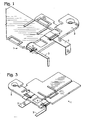
- Fig. 1 illustrates a perspective view of the first embodiment of a terminal plate circuit of the present invention
- Fig. 2 illustrates a side view thereof.
- a terminal plate circuit 1 includes a terminal plate 2, a rectangular wire 3, and a pressing member 4.
- a hole is provided of a degree such that the rectangular wire 3 penetrates but cannot move largely in the lateral directions.
- the rectangular wire 3 is inserted into this hole of the terminal plate 2 so as to make a state of electrical connection to the terminal plate 2.
- a part of the pressing member 4 presses onto the part of the surface of the rectangular wire 3 on the side opposite to the part of the surface of the rectangular wire 3 that is in contact with the terminal plate 2.
- the pressing member 4 has a part that can sandwich the end of the terminal plate 2 in a clip manner.
- a sandwiching force which is generated due to an action that a sandwiching pair of the sandwiching part tends to approach each other when sandwiching is made in this manner, a force that urges at least one of the sandwiching pair of the pressing member to press the rectangular wire 3 is generated.
- the sandwiching pair of the sandwiching part are at a distance closer than the width of the end of the terminal plate or are in contact with each other when they do not sandwich the end of the terminal plate, and generate a restoring force of tending to come closer to each other to return to the original state when they sandwich the end of the terminal plate. With this configuration, at least one of the sandwiching pair will have a pressing force to the rectangular wire 3.
- a part at which the pressing member 4 presses the rectangular wire 3 is not limited to a single part. As will be understood from Fig. 2 , it is preferable that the pressing member 4 presses the rectangular wire 3 at plural sites such as a part at which the rectangular wire 3 is in contact with the terminal plate in the hole of the terminal plate 2 and a part at which the rectangular wire 3 is in contact with the terminal plate 2 in a plane part outside of the hole of the terminal plate 2.
- the terminal plate 2 and the rectangular wire 3 used in the terminal plate circuit 1 of the present invention suitable selection may be made from among conventionally known ones.
- the terminal plate 2 is preferably enlarged as shown in Fig. 1 in order to enhance the cooling function thereof.
- the pressing member 4 any material (for example, metal or plastics) and shape can be adopted as long as it has a sandwiching part that can sandwich the end of the terminal plate 2 and generates a pressing force onto the rectangular wire 3 by sandwiching the end of the terminal plate 2 with this sandwiching part.
- the terminal plate circuit of the present invention can make a further firm electrical connection state between the terminal plate 2 and the rectangular wire 3 by performing soldering or welding so as to cover the part at which the terminal plate 2 and the rectangular wire 3 are in electrical contact with each other, in addition to the pressing of the pressing member 4 onto the rectangular wire 3 such as described above.
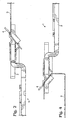
- Fig. 3 illustrates a perspective view of the second embodiment of a terminal plate circuit of the present invention
- Fig. 4 illustrates a side view thereof.
- the rectangular wire 3 is inserted into the hole of the terminal plate 2 from above, and is pressed onto the rectangular wire 2 from above by the pressing member 4.
- the rectangular wire 3 is inserted into the hole of the terminal plate 2 from below, and the rectangular wire is pressed from above by the pressing member 4.
- the second embodiment is basically the same as the first embodiment except for the above-described feature.
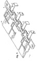
- Fig. 5 illustrates a perspective view of the third embodiment of a terminal plate circuit of the present invention.
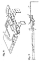
- Fig. 6 is a fractured perspective view illustrating a contact state of each constituent component of the third embodiment of the terminal plate circuit of the present invention
- Fig. 7 illustrates a side view thereof.
- the terminal plate circuit 1 of this third embodiment is constructed in such a manner that a rectangular wire 3 is inserted from between the divided sandwiching parts of a pressing member 4, and penetrates through a hole of a terminal plate 2 so as to make an electrical connection state between the rectangular wire 3 and the terminal plate 2. Then, in order to maintain this electrical connection state securely, the pressing member 4 presses onto the part of the surface of the rectangular wire 3 on the side opposite to the part of the surface of the rectangular wire 3 that is in contact with the terminal plate 2 while sandwiching the end of the terminal plate with the sandwiching parts of the pressing member 4.
- the state of pressing of the rectangular wire 3 onto the terminal plate 2 by this pressing member 4 can be best understood from Figs. 6 and 7 , and is basically achieved by a principle similar to that of the first embodiment.
- the terminal plate circuit of the present invention is suitable for the use in a severe environment such as within a terminal box for solar cell panel, because the reliability of an electrical connection state between a terminal plate and a rectangular wire is enhanced by a simple method.
Landscapes
- Photovoltaic Devices (AREA)
- Connections Effected By Soldering, Adhesion, Or Permanent Deformation (AREA)
Claims (4)
- Anschlussplattenschaltung (1) mit einer Anschlussplatte (2), einem rechteckigen Draht (3) und einem Druckelement (4), wobei ein Durchtritt, durch den der rechteckige Draht (3) verläuft, in der Anschlussplatte (2) vorgesehen ist, der rechteckige Draht (3) in diesen Durchtritt so eingesetzt ist, dass ein elektrischer Kontakt zwischen der Anschlussplatte (2) und dem rechteckigen Draht (3) zumindest in diesem Durchtritt ausgebildet ist, und der Kontaktzustand gehalten wird durch eine Druckkraft des Druckelements (4) auf den Teil der Oberfläche des rechteckigen Drahts (3) auf der Seite, die dem Teil der Oberfläche des rechteckigen Drahts (3), der mit der Anschlussplatte (2) in Kontakt ist, gegenüberliegt, dadurch gekennzeichnet, dass
das Druckelement (4) einen Aufnahmeteil aufweist, der das Ende der Anschlussplatte sandwichartig nach Art eines Clips aufnehmen kann, und die Druckkraft des Druckelements auf den rechteckigen Draht durch sandwichartiges Aufnehmen des Endes der Anschlussplatte mit diesem Aufnahmeteil erzeugt wird. - Anschlussplattenschaltung nach Anspruch 1, dadurch gekennzeichnet, dass die Anschlussplatte (2) und der rechteckige Draht (3) auch in einem flachen Teil außerhalb des Durchtritts der Anschlussplatte (2) in elektrischen Kontakt miteinander gebracht werden.
- Anschlussplattenschaltung nach Anspruch 1 oder 2, dadurch gekennzeichnet, dass zum Abdecken eines Teils, an dem die Anschlussplatte (2) und der rechteckige Draht (3) in elektrischen Kontakt miteinander sind, ein Löten oder Schweißen vorgenommen wird.
- Anschlussplattenschaltung nach einem der Ansprüche 1 bis 3, dadurch gekennzeichnet, dass die Anschlussplattenschaltung (1) in einer Anschlussbox für ein Solarzellenfeld verwendet wird.
Applications Claiming Priority (2)
| Application Number | Priority Date | Filing Date | Title |
|---|---|---|---|
| JP2007333449 | 2007-12-26 | ||
| PCT/JP2008/001630 WO2009081508A1 (ja) | 2007-12-26 | 2008-06-24 | 押付け部材を使用した端子板回路 |
Publications (3)
| Publication Number | Publication Date |
|---|---|
| EP2149932A1 EP2149932A1 (de) | 2010-02-03 |
| EP2149932A4 EP2149932A4 (de) | 2013-01-23 |
| EP2149932B1 true EP2149932B1 (de) | 2014-05-14 |
Family
ID=40800827
Family Applications (1)
| Application Number | Title | Priority Date | Filing Date |
|---|---|---|---|
| EP08764213.8A Not-in-force EP2149932B1 (de) | 2007-12-26 | 2008-06-24 | Endgerät-plattenschaltung mit einem schiebeelement |
Country Status (4)
| Country | Link |
|---|---|
| US (1) | US7955118B2 (de) |
| EP (1) | EP2149932B1 (de) |
| JP (1) | JP4799665B2 (de) |
| WO (1) | WO2009081508A1 (de) |
Families Citing this family (11)
| Publication number | Priority date | Publication date | Assignee | Title |
|---|---|---|---|---|
| JP5406843B2 (ja) * | 2009-07-27 | 2014-02-05 | オーナンバ株式会社 | 端子板回路 |
| JP2011119462A (ja) * | 2009-12-03 | 2011-06-16 | Hosiden Corp | 太陽電池モジュール用端子ボックス |
| EP2503642A1 (de) | 2010-04-07 | 2012-09-26 | Onamba Co., Ltd. | Anschlussbandschaltung |
| JP5294224B2 (ja) * | 2011-08-10 | 2013-09-18 | シャープ株式会社 | 太陽電池モジュール用の端子ボックス、リード線の挿通検査方法、挿通検査装置並びに太陽電池モジュールの製造方法及び製造システム |
| WO2013057224A1 (de) * | 2011-10-19 | 2013-04-25 | Saint-Gobain Glass France | Solarmodul mit flachbandleiter, sowie verfahren zu dessen herstellung |
| CN203150720U (zh) * | 2013-02-28 | 2013-08-21 | 泰科电子(上海)有限公司 | 弹簧夹和接线盒 |
| JP6362774B2 (ja) | 2015-05-13 | 2018-07-25 | 三菱電機株式会社 | 太陽電池モジュール及び太陽電池モジュールの製造方法 |
| USD834075S1 (en) | 2016-08-05 | 2018-11-20 | Ebara Corporation | Pressing member for substrate polishing apparatus |
| JP7215006B2 (ja) * | 2018-07-27 | 2023-01-31 | オムロン株式会社 | 端子着脱装置 |
| CN109524217A (zh) * | 2018-11-27 | 2019-03-26 | 保定天威互感器有限公司 | 一种互感器接线板分体固定装置及出线方法 |
| CN110880912B (zh) * | 2019-11-25 | 2020-12-04 | 湖南红太阳新能源科技有限公司 | 一种光伏接线盒的电气连接结构、接线盒及连接方法 |
Family Cites Families (9)
| Publication number | Priority date | Publication date | Assignee | Title |
|---|---|---|---|---|
| DE3739354A1 (de) * | 1987-11-20 | 1989-06-01 | Hochkoepper Paul Gmbh | Elektrische anschlussklemme |
| JPH0713196Y2 (ja) * | 1989-11-01 | 1995-03-29 | 株式会社ニチフ端子工業 | 電気接続子 |
| JP2913151B2 (ja) | 1995-03-30 | 1999-06-28 | 帝国通信工業株式会社 | 電子部品の端子部接続構造 |
| JP3600601B2 (ja) | 2002-07-26 | 2004-12-15 | オーナンバ株式会社 | 太陽電池パネル用端子ボックス |
| JP3493422B1 (ja) | 2003-04-07 | 2004-02-03 | エンゼル工業株式会社 | 半被覆ダイオードと太陽電池モジュール用端子ボックス |
| DE102004030085B4 (de) * | 2004-06-22 | 2013-09-26 | Wago Verwaltungsgesellschaft Mbh | Klemme zum Anschluß elektrischer Leiter und Klemmenanordnung |
| DE102005045596B3 (de) * | 2005-09-23 | 2007-06-21 | Siemens Ag | Feder-Steckklemme |
| DE102007024690B4 (de) * | 2007-05-25 | 2009-06-04 | Phoenix Contact Gmbh & Co. Kg | Elektrische Anschluß- oder Verbindungsklemme |
| US7722384B2 (en) * | 2007-07-09 | 2010-05-25 | Ideal Industries, Inc. | In-line push-in wire connector |
-
2008
- 2008-06-24 US US12/664,140 patent/US7955118B2/en not_active Expired - Fee Related
- 2008-06-24 EP EP08764213.8A patent/EP2149932B1/de not_active Not-in-force
- 2008-06-24 JP JP2009529442A patent/JP4799665B2/ja not_active Expired - Fee Related
- 2008-06-24 WO PCT/JP2008/001630 patent/WO2009081508A1/ja not_active Ceased
Also Published As
| Publication number | Publication date |
|---|---|
| US20100170716A1 (en) | 2010-07-08 |
| JP4799665B2 (ja) | 2011-10-26 |
| EP2149932A4 (de) | 2013-01-23 |
| US7955118B2 (en) | 2011-06-07 |
| WO2009081508A1 (ja) | 2009-07-02 |
| EP2149932A1 (de) | 2010-02-03 |
| JPWO2009081508A1 (ja) | 2011-05-06 |
Similar Documents
| Publication | Publication Date | Title |
|---|---|---|
| US7955118B2 (en) | Terminal plate circuit using a pressing member | |
| US7780460B2 (en) | Connecting terminal | |
| CN210120249U (zh) | 用于将导线与金属元件电连接的金属夹 | |
| US9711876B2 (en) | Clamping spring | |
| US20080045053A1 (en) | Contact element for connecting an electrical conductor | |
| US8803036B2 (en) | Electric heating device for a motor vehicle | |
| KR101504696B1 (ko) | 회로 기판에 고정하기 위한 접촉 소자, 접착 소자를 회로 기판에 고정하기 위한 방법, 및 회로 기판 | |
| EP2568539B1 (de) | Leiterverbindungswerkzeug und Relaiseinheit damit | |
| EP3425738B1 (de) | Verbinder | |
| US9543681B2 (en) | Terminal for an antenna connector | |
| US20160172771A1 (en) | Terminal for contacting an electrical conductor | |
| US20150136438A1 (en) | Electrical device with a busbar assembly having a frame providing access for laser welding | |
| JP2011119462A (ja) | 太陽電池モジュール用端子ボックス | |
| CN108574151B (zh) | 将电气部件安装在印刷电路板上的安装辅助件及安装方法 | |
| US10057987B2 (en) | Printed circuit board with side access termination pads | |
| KR20150036695A (ko) | 도전성 클립 | |
| JP5406843B2 (ja) | 端子板回路 | |
| US6685484B2 (en) | Electrical connector and terminal for flat circuitry | |
| JP2013161541A (ja) | 接続端子 | |
| JPH09213388A (ja) | ワイヤーハーネス及びワイヤーハーネスにおけるプリント回路基板と電線との接続方法 | |
| JP2013143186A (ja) | コネクタ装置 | |
| CN207705438U (zh) | 触点接通装置 | |
| EP2503642A1 (de) | Anschlussbandschaltung | |
| JP2021057195A (ja) | 端子、及び、端子と被取付面との組付構造 | |
| US10342117B2 (en) | Assembly |
Legal Events
| Date | Code | Title | Description |
|---|---|---|---|
| PUAI | Public reference made under article 153(3) epc to a published international application that has entered the european phase |
Free format text: ORIGINAL CODE: 0009012 |
|
| 17P | Request for examination filed |
Effective date: 20090922 |
|
| AK | Designated contracting states |
Kind code of ref document: A1 Designated state(s): AT BE BG CH CY CZ DE DK EE ES FI FR GB GR HR HU IE IS IT LI LT LU LV MC MT NL NO PL PT RO SE SI SK TR |
|
| AX | Request for extension of the european patent |
Extension state: AL BA MK RS |
|
| DAX | Request for extension of the european patent (deleted) | ||
| A4 | Supplementary search report drawn up and despatched |
Effective date: 20121221 |
|
| RIC1 | Information provided on ipc code assigned before grant |
Ipc: H01L 31/042 20060101ALI20121217BHEP Ipc: H01F 27/29 20060101ALI20121217BHEP Ipc: H01F 27/28 20060101ALI20121217BHEP Ipc: H01R 4/02 20060101AFI20121217BHEP |
|
| GRAP | Despatch of communication of intention to grant a patent |
Free format text: ORIGINAL CODE: EPIDOSNIGR1 |
|
| INTG | Intention to grant announced |
Effective date: 20131028 |
|
| GRAS | Grant fee paid |
Free format text: ORIGINAL CODE: EPIDOSNIGR3 |
|
| GRAA | (expected) grant |
Free format text: ORIGINAL CODE: 0009210 |
|
| AK | Designated contracting states |
Kind code of ref document: B1 Designated state(s): AT BE BG CH CY CZ DE DK EE ES FI FR GB GR HR HU IE IS IT LI LT LU LV MC MT NL NO PL PT RO SE SI SK TR |
|
| REG | Reference to a national code |
Ref country code: GB Ref legal event code: FG4D |
|
| REG | Reference to a national code |
Ref country code: AT Ref legal event code: REF Ref document number: 668895 Country of ref document: AT Kind code of ref document: T Effective date: 20140615 |
|
| REG | Reference to a national code |
Ref country code: IE Ref legal event code: FG4D |
|
| REG | Reference to a national code |
Ref country code: DE Ref legal event code: R096 Ref document number: 602008032282 Country of ref document: DE Effective date: 20140703 |
|
| REG | Reference to a national code |
Ref country code: NL Ref legal event code: VDEP Effective date: 20140514 Ref country code: AT Ref legal event code: MK05 Ref document number: 668895 Country of ref document: AT Kind code of ref document: T Effective date: 20140514 |
|
| REG | Reference to a national code |
Ref country code: LT Ref legal event code: MG4D |
|
| PG25 | Lapsed in a contracting state [announced via postgrant information from national office to epo] |
Ref country code: IS Free format text: LAPSE BECAUSE OF FAILURE TO SUBMIT A TRANSLATION OF THE DESCRIPTION OR TO PAY THE FEE WITHIN THE PRESCRIBED TIME-LIMIT Effective date: 20140914 Ref country code: GR Free format text: LAPSE BECAUSE OF FAILURE TO SUBMIT A TRANSLATION OF THE DESCRIPTION OR TO PAY THE FEE WITHIN THE PRESCRIBED TIME-LIMIT Effective date: 20140815 Ref country code: FI Free format text: LAPSE BECAUSE OF FAILURE TO SUBMIT A TRANSLATION OF THE DESCRIPTION OR TO PAY THE FEE WITHIN THE PRESCRIBED TIME-LIMIT Effective date: 20140514 Ref country code: NO Free format text: LAPSE BECAUSE OF FAILURE TO SUBMIT A TRANSLATION OF THE DESCRIPTION OR TO PAY THE FEE WITHIN THE PRESCRIBED TIME-LIMIT Effective date: 20140814 Ref country code: CY Free format text: LAPSE BECAUSE OF FAILURE TO SUBMIT A TRANSLATION OF THE DESCRIPTION OR TO PAY THE FEE WITHIN THE PRESCRIBED TIME-LIMIT Effective date: 20140514 Ref country code: LT Free format text: LAPSE BECAUSE OF FAILURE TO SUBMIT A TRANSLATION OF THE DESCRIPTION OR TO PAY THE FEE WITHIN THE PRESCRIBED TIME-LIMIT Effective date: 20140514 |
|
| PG25 | Lapsed in a contracting state [announced via postgrant information from national office to epo] |
Ref country code: SE Free format text: LAPSE BECAUSE OF FAILURE TO SUBMIT A TRANSLATION OF THE DESCRIPTION OR TO PAY THE FEE WITHIN THE PRESCRIBED TIME-LIMIT Effective date: 20140514 Ref country code: HR Free format text: LAPSE BECAUSE OF FAILURE TO SUBMIT A TRANSLATION OF THE DESCRIPTION OR TO PAY THE FEE WITHIN THE PRESCRIBED TIME-LIMIT Effective date: 20140514 Ref country code: ES Free format text: LAPSE BECAUSE OF FAILURE TO SUBMIT A TRANSLATION OF THE DESCRIPTION OR TO PAY THE FEE WITHIN THE PRESCRIBED TIME-LIMIT Effective date: 20140514 Ref country code: LV Free format text: LAPSE BECAUSE OF FAILURE TO SUBMIT A TRANSLATION OF THE DESCRIPTION OR TO PAY THE FEE WITHIN THE PRESCRIBED TIME-LIMIT Effective date: 20140514 Ref country code: AT Free format text: LAPSE BECAUSE OF FAILURE TO SUBMIT A TRANSLATION OF THE DESCRIPTION OR TO PAY THE FEE WITHIN THE PRESCRIBED TIME-LIMIT Effective date: 20140514 Ref country code: PL Free format text: LAPSE BECAUSE OF FAILURE TO SUBMIT A TRANSLATION OF THE DESCRIPTION OR TO PAY THE FEE WITHIN THE PRESCRIBED TIME-LIMIT Effective date: 20140514 |
|
| PG25 | Lapsed in a contracting state [announced via postgrant information from national office to epo] |
Ref country code: PT Free format text: LAPSE BECAUSE OF FAILURE TO SUBMIT A TRANSLATION OF THE DESCRIPTION OR TO PAY THE FEE WITHIN THE PRESCRIBED TIME-LIMIT Effective date: 20140915 |
|
| PG25 | Lapsed in a contracting state [announced via postgrant information from national office to epo] |
Ref country code: EE Free format text: LAPSE BECAUSE OF FAILURE TO SUBMIT A TRANSLATION OF THE DESCRIPTION OR TO PAY THE FEE WITHIN THE PRESCRIBED TIME-LIMIT Effective date: 20140514 Ref country code: BE Free format text: LAPSE BECAUSE OF FAILURE TO SUBMIT A TRANSLATION OF THE DESCRIPTION OR TO PAY THE FEE WITHIN THE PRESCRIBED TIME-LIMIT Effective date: 20140514 Ref country code: DK Free format text: LAPSE BECAUSE OF FAILURE TO SUBMIT A TRANSLATION OF THE DESCRIPTION OR TO PAY THE FEE WITHIN THE PRESCRIBED TIME-LIMIT Effective date: 20140514 Ref country code: RO Free format text: LAPSE BECAUSE OF FAILURE TO SUBMIT A TRANSLATION OF THE DESCRIPTION OR TO PAY THE FEE WITHIN THE PRESCRIBED TIME-LIMIT Effective date: 20140514 Ref country code: SK Free format text: LAPSE BECAUSE OF FAILURE TO SUBMIT A TRANSLATION OF THE DESCRIPTION OR TO PAY THE FEE WITHIN THE PRESCRIBED TIME-LIMIT Effective date: 20140514 |
|
| REG | Reference to a national code |
Ref country code: CH Ref legal event code: PL |
|
| REG | Reference to a national code |
Ref country code: DE Ref legal event code: R097 Ref document number: 602008032282 Country of ref document: DE |
|
| PG25 | Lapsed in a contracting state [announced via postgrant information from national office to epo] |
Ref country code: NL Free format text: LAPSE BECAUSE OF FAILURE TO SUBMIT A TRANSLATION OF THE DESCRIPTION OR TO PAY THE FEE WITHIN THE PRESCRIBED TIME-LIMIT Effective date: 20140514 |
|
| PLBE | No opposition filed within time limit |
Free format text: ORIGINAL CODE: 0009261 |
|
| STAA | Information on the status of an ep patent application or granted ep patent |
Free format text: STATUS: NO OPPOSITION FILED WITHIN TIME LIMIT |
|
| REG | Reference to a national code |
Ref country code: IE Ref legal event code: MM4A |
|
| REG | Reference to a national code |
Ref country code: FR Ref legal event code: ST Effective date: 20150227 |
|
| 26N | No opposition filed |
Effective date: 20150217 |
|
| GBPC | Gb: european patent ceased through non-payment of renewal fee |
Effective date: 20140814 |
|
| PG25 | Lapsed in a contracting state [announced via postgrant information from national office to epo] |
Ref country code: IE Free format text: LAPSE BECAUSE OF NON-PAYMENT OF DUE FEES Effective date: 20140624 Ref country code: LI Free format text: LAPSE BECAUSE OF NON-PAYMENT OF DUE FEES Effective date: 20140630 Ref country code: CH Free format text: LAPSE BECAUSE OF NON-PAYMENT OF DUE FEES Effective date: 20140630 |
|
| REG | Reference to a national code |
Ref country code: DE Ref legal event code: R097 Ref document number: 602008032282 Country of ref document: DE Effective date: 20150217 |
|
| PG25 | Lapsed in a contracting state [announced via postgrant information from national office to epo] |
Ref country code: FR Free format text: LAPSE BECAUSE OF NON-PAYMENT OF DUE FEES Effective date: 20140715 |
|
| PG25 | Lapsed in a contracting state [announced via postgrant information from national office to epo] |
Ref country code: SI Free format text: LAPSE BECAUSE OF FAILURE TO SUBMIT A TRANSLATION OF THE DESCRIPTION OR TO PAY THE FEE WITHIN THE PRESCRIBED TIME-LIMIT Effective date: 20140514 Ref country code: GB Free format text: LAPSE BECAUSE OF NON-PAYMENT OF DUE FEES Effective date: 20140814 |
|
| PG25 | Lapsed in a contracting state [announced via postgrant information from national office to epo] |
Ref country code: MT Free format text: LAPSE BECAUSE OF FAILURE TO SUBMIT A TRANSLATION OF THE DESCRIPTION OR TO PAY THE FEE WITHIN THE PRESCRIBED TIME-LIMIT Effective date: 20140514 |
|
| PG25 | Lapsed in a contracting state [announced via postgrant information from national office to epo] |
Ref country code: MC Free format text: LAPSE BECAUSE OF FAILURE TO SUBMIT A TRANSLATION OF THE DESCRIPTION OR TO PAY THE FEE WITHIN THE PRESCRIBED TIME-LIMIT Effective date: 20140514 |
|
| PG25 | Lapsed in a contracting state [announced via postgrant information from national office to epo] |
Ref country code: BG Free format text: LAPSE BECAUSE OF FAILURE TO SUBMIT A TRANSLATION OF THE DESCRIPTION OR TO PAY THE FEE WITHIN THE PRESCRIBED TIME-LIMIT Effective date: 20140514 |
|
| PG25 | Lapsed in a contracting state [announced via postgrant information from national office to epo] |
Ref country code: HU Free format text: LAPSE BECAUSE OF FAILURE TO SUBMIT A TRANSLATION OF THE DESCRIPTION OR TO PAY THE FEE WITHIN THE PRESCRIBED TIME-LIMIT; INVALID AB INITIO Effective date: 20080624 Ref country code: LU Free format text: LAPSE BECAUSE OF NON-PAYMENT OF DUE FEES Effective date: 20140624 Ref country code: TR Free format text: LAPSE BECAUSE OF FAILURE TO SUBMIT A TRANSLATION OF THE DESCRIPTION OR TO PAY THE FEE WITHIN THE PRESCRIBED TIME-LIMIT Effective date: 20140514 |
|
| PGFP | Annual fee paid to national office [announced via postgrant information from national office to epo] |
Ref country code: CZ Payment date: 20160513 Year of fee payment: 9 |
|
| PGFP | Annual fee paid to national office [announced via postgrant information from national office to epo] |
Ref country code: IT Payment date: 20160608 Year of fee payment: 9 |
|
| PGFP | Annual fee paid to national office [announced via postgrant information from national office to epo] |
Ref country code: DE Payment date: 20170622 Year of fee payment: 10 |
|
| PG25 | Lapsed in a contracting state [announced via postgrant information from national office to epo] |
Ref country code: CZ Free format text: LAPSE BECAUSE OF NON-PAYMENT OF DUE FEES Effective date: 20170624 |
|
| PG25 | Lapsed in a contracting state [announced via postgrant information from national office to epo] |
Ref country code: IT Free format text: LAPSE BECAUSE OF NON-PAYMENT OF DUE FEES Effective date: 20170624 |
|
| REG | Reference to a national code |
Ref country code: DE Ref legal event code: R119 Ref document number: 602008032282 Country of ref document: DE |
|
| PG25 | Lapsed in a contracting state [announced via postgrant information from national office to epo] |
Ref country code: DE Free format text: LAPSE BECAUSE OF NON-PAYMENT OF DUE FEES Effective date: 20190101 |