EP2149963B1 - Moteur à spin magnétique - Google Patents
Moteur à spin magnétique Download PDFInfo
- Publication number
- EP2149963B1 EP2149963B1 EP20090164351 EP09164351A EP2149963B1 EP 2149963 B1 EP2149963 B1 EP 2149963B1 EP 20090164351 EP20090164351 EP 20090164351 EP 09164351 A EP09164351 A EP 09164351A EP 2149963 B1 EP2149963 B1 EP 2149963B1
- Authority
- EP
- European Patent Office
- Prior art keywords
- pole
- magnet
- rotor
- electromagnet
- permanent magnets
- Prior art date
- Legal status (The legal status is an assumption and is not a legal conclusion. Google has not performed a legal analysis and makes no representation as to the accuracy of the status listed.)
- Not-in-force
Links
- 230000005291 magnetic effect Effects 0.000 claims description 25
- 238000000034 method Methods 0.000 claims description 5
- 230000003993 interaction Effects 0.000 claims description 3
- 230000004907 flux Effects 0.000 description 4
- 230000000694 effects Effects 0.000 description 3
- XEEYBQQBJWHFJM-UHFFFAOYSA-N Iron Chemical compound [Fe] XEEYBQQBJWHFJM-UHFFFAOYSA-N 0.000 description 2
- 230000001419 dependent effect Effects 0.000 description 2
- 230000007704 transition Effects 0.000 description 2
- 238000004804 winding Methods 0.000 description 2
- 241000446313 Lamella Species 0.000 description 1
- 206010034016 Paronychia Diseases 0.000 description 1
- 230000008859 change Effects 0.000 description 1
- 230000000295 complement effect Effects 0.000 description 1
- 238000010276 construction Methods 0.000 description 1
- 230000007717 exclusion Effects 0.000 description 1
- 239000003302 ferromagnetic material Substances 0.000 description 1
- 239000011888 foil Substances 0.000 description 1
- 230000006698 induction Effects 0.000 description 1
- 238000009413 insulation Methods 0.000 description 1
- 229910052742 iron Inorganic materials 0.000 description 1
- 230000002045 lasting effect Effects 0.000 description 1
- 230000005285 magnetism related processes and functions Effects 0.000 description 1
- 239000000463 material Substances 0.000 description 1
- 230000007935 neutral effect Effects 0.000 description 1
- 230000001846 repelling effect Effects 0.000 description 1
- 239000000126 substance Substances 0.000 description 1
- 230000001360 synchronised effect Effects 0.000 description 1
- 238000006891 umpolung reaction Methods 0.000 description 1
- 229910000859 α-Fe Inorganic materials 0.000 description 1
Images


Classifications
-
- H—ELECTRICITY
- H02—GENERATION; CONVERSION OR DISTRIBUTION OF ELECTRIC POWER
- H02K—DYNAMO-ELECTRIC MACHINES
- H02K1/00—Details of the magnetic circuit
- H02K1/06—Details of the magnetic circuit characterised by the shape, form or construction
- H02K1/22—Rotating parts of the magnetic circuit
- H02K1/223—Rotor cores with windings and permanent magnets
-
- H—ELECTRICITY
- H02—GENERATION; CONVERSION OR DISTRIBUTION OF ELECTRIC POWER
- H02K—DYNAMO-ELECTRIC MACHINES
- H02K1/00—Details of the magnetic circuit
- H02K1/06—Details of the magnetic circuit characterised by the shape, form or construction
- H02K1/12—Stationary parts of the magnetic circuit
- H02K1/17—Stator cores with permanent magnets
Definitions
- the invention relates to a magnet spin motor according to the preamble of patent claim 1 and a method for operating such a magnet spin motor according to claim 6.
- JP-A-2004/147425 describes a rotary electric machine in which the torque is to be improved.
- a rotor 1 is fixed to a non-magnetic tube 3 which is surrounded by an annular magnetic body 4.
- On the magnetic body 4 four uniformly spaced apart (by 90 °) arranged permanent magnets 5 are fixed, the north and south poles are axially aligned and are arranged alternately with respect to the north and south poles. Between the permanent magnets 5 non-magnetic intermediate pieces 3a are provided.
- the stator 6 has a tubular stator core 7 with projecting pole pieces 8, which are arranged at a uniform distance from each other (by 30 °).
- the pole pieces 8 are surrounded by a coil 12 and thus form the electromagnet 13.
- the magnetic fields of the electromagnets 13 are aligned radially and are arranged alternately in the field direction. Between the electromagnets 13 permanent magnets 9 are arranged whose magnetic fields are aligned in a circle and whose poles are provided corresponding to the poles (N / S) of the electromagnets 13. With respect to the magnetic pole of the stator 6, the magnetic flux generated by the electromagnet 13 superimposes those of the applied permanent magnets 9.
- the rotor 1 is driven by repelling the magnetic pole of the rotor of the same polarity and the attraction of the magnetic pole of the rotor of opposite polarity.
- This is a synchronous motor, in which the electromagnets out of phase are each subjected to a DC pulse.
- DE-U-299 21 874 describes an electromagnetic machine for a bicycle having a coil unit on a vehicle frame and a return part on a vehicle wheel. This is a dynamo that should generate electrical energy and not an electric motor.
- the rotor consists of two permanent magnets 51 and 52, which are oppositely poled and are magnetically connected via a yoke 53. Coils 7 and 9 are arranged around the permanent magnets 51 and 52, so that the magnetic fields of the permanent magnets 51 and 52 and the coils 7 and 9 are aligned the same.
- protruding teeth 11 are provided, which shoot with the permanent magnets 51 and 52 with the coils 7 and 9, the magnetic circuit. From which material the ring gear 3 is not described. From experience, however, it must be assumed that it is a ferromagnetic material such as iron.
- the present invention has for its object to provide a motor in which this disadvantage is much smaller.
- the structure corresponds in principle to the known types of a collector motor, consisting of a stationary part, called stator, and a rotatable about an axis part, called a rotor. Distinct pole heads are provided on the rotor and stator.
- a collector causes the required polarity reversal of the pole heads, for example, those of the rotor at the moment of coincidence with those of the stator.
- the innovation relates in particular to the pole heads, the rotor or the stator. They allow a polarity reversal without a lasting braking induction effect occurs in the switching windings.
- the pole heads of the stator are consistently equipped with permanent magnets, the rotor in half.
- the other half occupies a polarity causing the polarity reversal, whose field is also involved in the drive.
- the engine is operated with direct current, whereby this is converted by means of the collector in speed-dependent alternating current for feeding the electromagnet.
- the amperage is set so that, depending on the momentary polarity of the electro-magnet (called E-magnet), it neutralizes one or the other of the counter-poled permanent magnets (called P-magnet) to a magnetically closed circuit, while at the same time the field of the other P-magnet, in this case the same polarity to the field of the E-magnet, is doubled and both contribute together to the drive.
- E-magnet momentary polarity of the electro-magnet
- P-magnet counter-poled permanent magnets
- phase position of the alternating current, adjustable at the collector is such that the respectively over the air gap corresponding Polkmü tighten at field inlet, repel at the field outlet, creating a same direction torque.
- FIGS. 1a to 1d the concept of the rotor according to the invention is illustrated in more detail.
- the FIGS. 1a to 1d show the structure of a pole head and the FIGS. 2a to 2c the switching principle in three positions when rotating the rotor.
- FIG. 1a shows a front view
- FIG. 1b the top view according to FIG. 1a
- Figure 1c a side view
- Figure 1d the top view according to Figure 1c
- the Umpolung causing E-magnet with a core 1 and a wire coil 2 are located in the center of the pole head.
- P magnets permanent magnets
- Both pairs are counterpolar. They are also each magnetically connected with tabs 5 and 6, which are also in magnetic connection with the core 1 of the E-magnet.
- a console 7 on the opposite side causes the magnetic closure for all magnets.
- Winding and control current are chosen so that the field of the E-magnet, depending on the polarity, always that of the complementary tab, at least approximated (same flux), added to a magnetically closed circle, while at the same time the field of the other tab, reinforced by the opposing field of the e-magnet in the sense of a magnetically closed through the air gap closed circuit causes (see FIGS. 3 and 4 ).
- the possible directions of rotation are in Fig. 1a marked with R.
- FIGS. 2a to 2c The interplay of the magnetic fields regarding polarity reversal and drive is in the FIGS. 2a to 2c shown.
- the view of the pole heads corresponds to the section pp in FIG. 1b ,
- the registered polarities are arbitrary; they could be the other way round too.
- the running direction is indicated by the arrow S.
- the pole face of the P magnet 8 is approximately the same size (with the same field strengths) as the entire pole faces of the P magnets 3 and 4 on the rotor. Any screw connections are omitted.
- the tabs 5 and 6 have, from their P-magnet forth, in all three positions of the rotor always the same polarities; Pole left + pole right. It is assumed that the P magnet 8 is a pole toward the rotor. The E-magnet then has the + pole at the top. It now complements the field of tab 5 to a complete magnetic circuit. The tab 5 is then the outside, with sufficient thickness, field-free. The tab 6, the same polarity to the field of the E-magnet, doubles the flux to the stator magnet 8. In 2b (Pole change) the electric magnet is momentarily field-free due to current interruption. The gegengepolten fields of the tabs 5 and 6 close over the core 1 to a full magnetic circuit in principle. The outer surfaces of both tabs are almost field-free.
- stator P magnets which are established in a rotary plane of the rotor are all the same polarity. As the rotor passes to the next stator P magnet, the E magnet is reversed, approximately halfway, and the interplay of the magnetic fields begins again. The switching frequency is therefore twice as high as the rotational frequency of the rotor.
- the associated collector is in four parts, with two diametrically opposite segments are electrically connected. At the transition from one segment to the next there is a neutral lamella, so that when the current direction changes a short-term power interruption occurs.
- the two required collector brushes are offset by 90 ° on the brush bridge and, if necessary, can still be moved azimuthally so that optimum torque can be set.
- the effects may be greater if there is no clearance between the tabs and the magnetic surfaces.
- a thin foil (0.01 mm) as an intermediate layer is sufficient.
- the three faces, the E-magnet and the two P-magnets do not need to be exactly on the same plane.
- the distance of the E-magnet to the tabs can also be slightly larger (0.1 to 0.3 mm), which, however, has a larger switching capacity result.
- the magnetic processes are effectively more involved than stated here.
- the DC fields of the P magnets 3 and 4 or in the tabs 5 and 6 are partially directed axially at least in the region of the crossed wire spool. In the area of the E-magnet, these axial DC fields are deflected into radial alternating fields. Also at the transition to the stator magnets are radial field components available. In the drive-causing flooding the P-magnets are to 3/4 and the E-magnet to 1/4 involved (a special feature!). Due to the relatively low influence of the e-magnet on the torque, the performance-decelerating self-induction also hardly matters.
- pole heads also requires measures against susceptible eddy currents. Particularly affected are the core 1 and the tabs 5 and 6. Proven means, however, are inter alia laminated cores with intermediate insulation, but also substances with particularly poor electrical conductivity such. Ferrites.
- a flux reaching from the rotor to the stator must have a return path to the rotor closing the magnetic circuit.
- a same, polar opposite polarity (arranged with opposite poles on the stator).
- the pairwise magnetically acting rotor and stator magnets each have, on the side facing away from the air gap sides, common brackets, whereby the magnetic circuit is closed.
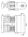
- FIG. 3 The just revealed combination at the moment of a pile round is in FIG. 3 in a front view, in FIG. 4 shown in a side view.
- the components are up to and with index 9 (without 7) the same as according to the FIGS. 1 and 2 described.
- the at least approximately identically identical pole heads are each a gegengepoltes pair (including the stator magnets) in the relatively small axial distance A on the brackets 11 and 12 attached.
- the console 12 is connected via the centering base 13 with the rotor shaft 14.
- the magnetic closure across the air gap 15 with coincidence of the rotor and stator pole heads is obvious.
- the direction of the torque (left or right-hand rotation) of the second, all-polarity magnet system (see Fig. 3 ) is necessarily the same as that of the first magnet system.
- the original torque is doubled.
Landscapes
- Engineering & Computer Science (AREA)
- Power Engineering (AREA)
- Permanent Magnet Type Synchronous Machine (AREA)
- Permanent Field Magnets Of Synchronous Machinery (AREA)
Claims (8)
- Moteur à spin magnétique composé d'une partie fixe appelée stator et d'une partie capable de rotation, concentrique du stator et appelée rotor, dans lequel le rotor et le stator sont garnis de façon continue de bornes polaires en relief qui sont en interaction magnétique par l'intermédiaire d'un entrefer, caractérisé en ce que soit, sur un premier rotor, chaque borne polaire contient au moins un électroaimant (1, 2) qui provoque des inversions de polarité de la borne polaire et avec celui-ci au moins deux aimants permanents (3, 4) de pôles opposés par paire et, sur un premier stator correspondant, les bornes polaires sont équipées de façon continue d'aimants permanents (8) de même polarité, soit, dans un deuxième stator, chaque borne polaire contient au moins un électroaimant qui provoque des inversions de polarité de la borne polaire et avec celui-ci au moins deux aimants permanents de pôles opposés par paire et, sur un premier stator correspondant, les bornes polaires sont équipées de façon continue d'aimants permanents de même polarité.
- Moteur à spin magnétique selon la revendication 1, caractérisé en ce que l'électroaimant (1, 2), compartant un noyau (1) et une bobine d'excitation (2), est supporté au moins approximativement au centre de la borne polaire et les aimants permanents (3, 4) sont disposés à l'extérieur de la bobine d'excitation (2).
- Moteur à spin magnétique selon la revendication 2, caractérisé en ce que l'électroaimant (1, 2) et les aimants permanents (3, 4) sont reliés magnétiquement sur le côté opposé à l'entrefer et en ce que les aimants permanents (3, 4) sont reliés magnétiquement au noyau (1) de l'électroaimant sur le côté tourné vers l'entrefer, à une distance mutuelle discrète.
- Moteur à spin magnétique selon l'une des revendications 1 à 3, caractérisé en ce qu'un collecteur et des bagues collectrices sont prévus pour l'inversion de polarité.
- Moteur à spin magnétique selon l'une des revendications 1 à 4, caractérisé en ce qu'il est prévu à côté de chaque première borne polaire, décalée axialement (A), une deuxième borne polaire identique mécaniquement, chaque aimant de la deuxième la borne polaire étant de polarité opposée à celui de la première borne polaire et ces paires de bornes polaires étant reliées magnétiquement par des consoles (11, 12) sur les côtés opposés à l'entrefer.
- Procédé d'exploitation d'un moteur à spin magnétique selon l'une des revendications 1 à 5, caractérisé en ce que le courant d'excitation de l'électroaimant (1, 2) est choisi de telle façon que le champ alternatif de l'un des aimants permanents (4, 5) soit neutralisé dans un circuit fermé magnétique tandis que le champ de l'autre aimant permanent (3, 5) est doublé.
- Procédé selon la revendication 6, caractérisé en ce que la fréquence de commutation à laquelle la polarité de l'électroaimant (1, 2) est inversée est deux fois plus élevée que la fréquence de révolution du rotor.
- Procédé selon la revendication 7, caractérisé en ce que la fréquence de commutation est produite en synchronisation avec la vitesse de rotation du moteur au moyen du collecteur et des bagues collectrices.
Applications Claiming Priority (1)
| Application Number | Priority Date | Filing Date | Title |
|---|---|---|---|
| CH10712008A CH699130B1 (de) | 2008-07-09 | 2008-07-09 | Magnetspinmotor. |
Publications (3)
| Publication Number | Publication Date |
|---|---|
| EP2149963A2 EP2149963A2 (fr) | 2010-02-03 |
| EP2149963A3 EP2149963A3 (fr) | 2010-10-13 |
| EP2149963B1 true EP2149963B1 (fr) | 2012-09-12 |
Family
ID=41429682
Family Applications (1)
| Application Number | Title | Priority Date | Filing Date |
|---|---|---|---|
| EP20090164351 Not-in-force EP2149963B1 (fr) | 2008-07-09 | 2009-07-01 | Moteur à spin magnétique |
Country Status (2)
| Country | Link |
|---|---|
| EP (1) | EP2149963B1 (fr) |
| CH (1) | CH699130B1 (fr) |
Families Citing this family (2)
| Publication number | Priority date | Publication date | Assignee | Title |
|---|---|---|---|---|
| GB2535161A (en) * | 2015-02-09 | 2016-08-17 | Skf Ab | Power generator assembly for rotating applications |
| GB2535160A (en) * | 2015-02-09 | 2016-08-17 | Skf Ab | Power generator assembly for rotating applications |
Family Cites Families (5)
| Publication number | Priority date | Publication date | Assignee | Title |
|---|---|---|---|---|
| US4972112A (en) * | 1989-06-12 | 1990-11-20 | Kim Dae W | Brushless DC motor |
| DE29921874U1 (de) * | 1999-12-13 | 2000-04-13 | Müller, Michael, 51377 Leverkusen | Elektromagnetische Maschine für ein Fahrzeug, insbesondere ein Fahrrad |
| WO2002047237A1 (fr) * | 2000-12-06 | 2002-06-13 | Ali Cavusoglu | Moteurs ps |
| JP4160358B2 (ja) * | 2002-10-24 | 2008-10-01 | 夏目光学株式会社 | 回転電機 |
| US7737594B2 (en) * | 2006-12-01 | 2010-06-15 | Honda Motor Co., Ltd. | Axial gap type motor |
-
2008
- 2008-07-09 CH CH10712008A patent/CH699130B1/de not_active IP Right Cessation
-
2009
- 2009-07-01 EP EP20090164351 patent/EP2149963B1/fr not_active Not-in-force
Also Published As
| Publication number | Publication date |
|---|---|
| EP2149963A3 (fr) | 2010-10-13 |
| CH699130A2 (de) | 2010-01-15 |
| EP2149963A2 (fr) | 2010-02-03 |
| CH699130B1 (de) | 2010-05-14 |
Similar Documents
| Publication | Publication Date | Title |
|---|---|---|
| EP2639936B1 (fr) | Machine électrique à rotor excité en permanence et rotor excité en permanence correspondant | |
| DE102004017157B4 (de) | Verfahren zur Herstellung einer Rotoranordnung und Rotoranordnung für eine elektrische Maschine | |
| DE2225442A1 (de) | Kollektorloser gleichstrom-motor | |
| DE102016202477B4 (de) | Elektrische maschine | |
| DE102015110652B4 (de) | Rotor-stator-anordnung für eine hybriderregte synchronmaschine und ein rotor dafür | |
| EP3545610A1 (fr) | Machine synchrone à démultiplication magnétique de champ tournant et concentration de flux | |
| WO2014127855A1 (fr) | Moteur électrique pourvu d'un stator divisé | |
| DE3730615A1 (de) | Elektrische maschine mit permanentmagnet-erregung | |
| DE112019007070T5 (de) | Rotierende elektrische maschine | |
| EP2997644A2 (fr) | Rotor pour machine électromécanique | |
| DE102020112423A1 (de) | Rotor für einen axialfluss-elektromotor, axialfluss-elektromotor mit einem solchen rotor, und verfahren zum herstellen eines rotors für eine rotierende elektrische maschine | |
| DE102010036828A1 (de) | Stator für elektrische Maschine mit überlappenden U-förmigen Kernblechen | |
| DE102016113188A1 (de) | Bremssystem und Verfahren zum Betreiben eines Bremssystems | |
| EP2149963A2 (fr) | Moteur à spin magnétique | |
| DE3037724C2 (de) | Gleichstrommotor | |
| WO2001042079A1 (fr) | Machine electromagnetique pour un vehicule, en particulier pour une bicyclette | |
| DE3317129C2 (de) | Magnetisches Getriebe | |
| DE102016201094A1 (de) | Elektrische Maschine | |
| DE1488053B2 (de) | Rotierende elektrische gleichstrommaschine fuer niedrige spannungen und grosse stromstaerken | |
| DE102014106620B4 (de) | Mittelläufermotor | |
| DE102016201092A1 (de) | Elektrische Maschine | |
| DE102019129782B4 (de) | Multipol-GENERATOR mit Gesamtmagnetfluss umschließenden Spulen | |
| EP3198707B1 (fr) | Transducteur électrodynamique | |
| DE68911905T2 (de) | Elektrischer Motor ohne Stromwenderteile mit in der Richtung der Achse aufgestellten Polen und auf demselben Prinzip basierender magnetischer Motor. | |
| EP1758229B1 (fr) | Moteur électrique |
Legal Events
| Date | Code | Title | Description |
|---|---|---|---|
| PUAI | Public reference made under article 153(3) epc to a published international application that has entered the european phase |
Free format text: ORIGINAL CODE: 0009012 |
|
| AK | Designated contracting states |
Kind code of ref document: A2 Designated state(s): AT BE BG CH CY CZ DE DK EE ES FI FR GB GR HR HU IE IS IT LI LT LU LV MC MK MT NL NO PL PT RO SE SI SK SM TR |
|
| AX | Request for extension of the european patent |
Extension state: AL BA RS |
|
| PUAL | Search report despatched |
Free format text: ORIGINAL CODE: 0009013 |
|
| AK | Designated contracting states |
Kind code of ref document: A3 Designated state(s): AT BE BG CH CY CZ DE DK EE ES FI FR GB GR HR HU IE IS IT LI LT LU LV MC MK MT NL NO PL PT RO SE SI SK SM TR |
|
| AX | Request for extension of the european patent |
Extension state: AL BA RS |
|
| RIC1 | Information provided on ipc code assigned before grant |
Ipc: H02K 1/17 20060101ALI20100907BHEP Ipc: H02K 1/22 20060101AFI20091229BHEP |
|
| 17P | Request for examination filed |
Effective date: 20110408 |
|
| 17Q | First examination report despatched |
Effective date: 20110704 |
|
| GRAP | Despatch of communication of intention to grant a patent |
Free format text: ORIGINAL CODE: EPIDOSNIGR1 |
|
| GRAS | Grant fee paid |
Free format text: ORIGINAL CODE: EPIDOSNIGR3 |
|
| GRAA | (expected) grant |
Free format text: ORIGINAL CODE: 0009210 |
|
| AK | Designated contracting states |
Kind code of ref document: B1 Designated state(s): AT BE BG CH CY CZ DE DK EE ES FI FR GB GR HR HU IE IS IT LI LT LU LV MC MK MT NL NO PL PT RO SE SI SK SM TR |
|
| REG | Reference to a national code |
Ref country code: GB Ref legal event code: FG4D Free format text: NOT ENGLISH |
|
| REG | Reference to a national code |
Ref country code: CH Ref legal event code: EP |
|
| REG | Reference to a national code |
Ref country code: AT Ref legal event code: REF Ref document number: 575431 Country of ref document: AT Kind code of ref document: T Effective date: 20120915 |
|
| REG | Reference to a national code |
Ref country code: IE Ref legal event code: FG4D Free format text: LANGUAGE OF EP DOCUMENT: GERMAN |
|
| REG | Reference to a national code |
Ref country code: DE Ref legal event code: R096 Ref document number: 502009004708 Country of ref document: DE Effective date: 20121108 |
|
| REG | Reference to a national code |
Ref country code: CH Ref legal event code: NV Representative=s name: SPIERENBURG AND PARTNER AG, PATENT- UND MARKEN, CH |
|
| PG25 | Lapsed in a contracting state [announced via postgrant information from national office to epo] |
Ref country code: FI Free format text: LAPSE BECAUSE OF FAILURE TO SUBMIT A TRANSLATION OF THE DESCRIPTION OR TO PAY THE FEE WITHIN THE PRESCRIBED TIME-LIMIT Effective date: 20120912 Ref country code: CY Free format text: LAPSE BECAUSE OF FAILURE TO SUBMIT A TRANSLATION OF THE DESCRIPTION OR TO PAY THE FEE WITHIN THE PRESCRIBED TIME-LIMIT Effective date: 20120912 Ref country code: LT Free format text: LAPSE BECAUSE OF FAILURE TO SUBMIT A TRANSLATION OF THE DESCRIPTION OR TO PAY THE FEE WITHIN THE PRESCRIBED TIME-LIMIT Effective date: 20120912 Ref country code: HR Free format text: LAPSE BECAUSE OF FAILURE TO SUBMIT A TRANSLATION OF THE DESCRIPTION OR TO PAY THE FEE WITHIN THE PRESCRIBED TIME-LIMIT Effective date: 20120912 Ref country code: NO Free format text: LAPSE BECAUSE OF FAILURE TO SUBMIT A TRANSLATION OF THE DESCRIPTION OR TO PAY THE FEE WITHIN THE PRESCRIBED TIME-LIMIT Effective date: 20121212 |
|
| REG | Reference to a national code |
Ref country code: NL Ref legal event code: VDEP Effective date: 20120912 |
|
| REG | Reference to a national code |
Ref country code: LT Ref legal event code: MG4D Effective date: 20120912 |
|
| PG25 | Lapsed in a contracting state [announced via postgrant information from national office to epo] |
Ref country code: LV Free format text: LAPSE BECAUSE OF FAILURE TO SUBMIT A TRANSLATION OF THE DESCRIPTION OR TO PAY THE FEE WITHIN THE PRESCRIBED TIME-LIMIT Effective date: 20120912 Ref country code: SE Free format text: LAPSE BECAUSE OF FAILURE TO SUBMIT A TRANSLATION OF THE DESCRIPTION OR TO PAY THE FEE WITHIN THE PRESCRIBED TIME-LIMIT Effective date: 20120912 Ref country code: GR Free format text: LAPSE BECAUSE OF FAILURE TO SUBMIT A TRANSLATION OF THE DESCRIPTION OR TO PAY THE FEE WITHIN THE PRESCRIBED TIME-LIMIT Effective date: 20121213 Ref country code: SI Free format text: LAPSE BECAUSE OF FAILURE TO SUBMIT A TRANSLATION OF THE DESCRIPTION OR TO PAY THE FEE WITHIN THE PRESCRIBED TIME-LIMIT Effective date: 20120912 |
|
| PG25 | Lapsed in a contracting state [announced via postgrant information from national office to epo] |
Ref country code: EE Free format text: LAPSE BECAUSE OF FAILURE TO SUBMIT A TRANSLATION OF THE DESCRIPTION OR TO PAY THE FEE WITHIN THE PRESCRIBED TIME-LIMIT Effective date: 20120912 Ref country code: IS Free format text: LAPSE BECAUSE OF FAILURE TO SUBMIT A TRANSLATION OF THE DESCRIPTION OR TO PAY THE FEE WITHIN THE PRESCRIBED TIME-LIMIT Effective date: 20130112 Ref country code: CZ Free format text: LAPSE BECAUSE OF FAILURE TO SUBMIT A TRANSLATION OF THE DESCRIPTION OR TO PAY THE FEE WITHIN THE PRESCRIBED TIME-LIMIT Effective date: 20120912 Ref country code: RO Free format text: LAPSE BECAUSE OF FAILURE TO SUBMIT A TRANSLATION OF THE DESCRIPTION OR TO PAY THE FEE WITHIN THE PRESCRIBED TIME-LIMIT Effective date: 20120912 Ref country code: ES Free format text: LAPSE BECAUSE OF FAILURE TO SUBMIT A TRANSLATION OF THE DESCRIPTION OR TO PAY THE FEE WITHIN THE PRESCRIBED TIME-LIMIT Effective date: 20121223 Ref country code: NL Free format text: LAPSE BECAUSE OF FAILURE TO SUBMIT A TRANSLATION OF THE DESCRIPTION OR TO PAY THE FEE WITHIN THE PRESCRIBED TIME-LIMIT Effective date: 20120912 |
|
| PG25 | Lapsed in a contracting state [announced via postgrant information from national office to epo] |
Ref country code: PL Free format text: LAPSE BECAUSE OF FAILURE TO SUBMIT A TRANSLATION OF THE DESCRIPTION OR TO PAY THE FEE WITHIN THE PRESCRIBED TIME-LIMIT Effective date: 20120912 Ref country code: SK Free format text: LAPSE BECAUSE OF FAILURE TO SUBMIT A TRANSLATION OF THE DESCRIPTION OR TO PAY THE FEE WITHIN THE PRESCRIBED TIME-LIMIT Effective date: 20120912 Ref country code: PT Free format text: LAPSE BECAUSE OF FAILURE TO SUBMIT A TRANSLATION OF THE DESCRIPTION OR TO PAY THE FEE WITHIN THE PRESCRIBED TIME-LIMIT Effective date: 20130114 |
|
| PLBE | No opposition filed within time limit |
Free format text: ORIGINAL CODE: 0009261 |
|
| STAA | Information on the status of an ep patent application or granted ep patent |
Free format text: STATUS: NO OPPOSITION FILED WITHIN TIME LIMIT |
|
| PG25 | Lapsed in a contracting state [announced via postgrant information from national office to epo] |
Ref country code: BG Free format text: LAPSE BECAUSE OF FAILURE TO SUBMIT A TRANSLATION OF THE DESCRIPTION OR TO PAY THE FEE WITHIN THE PRESCRIBED TIME-LIMIT Effective date: 20121212 Ref country code: DK Free format text: LAPSE BECAUSE OF FAILURE TO SUBMIT A TRANSLATION OF THE DESCRIPTION OR TO PAY THE FEE WITHIN THE PRESCRIBED TIME-LIMIT Effective date: 20120912 |
|
| PGFP | Annual fee paid to national office [announced via postgrant information from national office to epo] |
Ref country code: CH Payment date: 20130611 Year of fee payment: 5 |
|
| 26N | No opposition filed |
Effective date: 20130613 |
|
| PG25 | Lapsed in a contracting state [announced via postgrant information from national office to epo] |
Ref country code: IT Free format text: LAPSE BECAUSE OF FAILURE TO SUBMIT A TRANSLATION OF THE DESCRIPTION OR TO PAY THE FEE WITHIN THE PRESCRIBED TIME-LIMIT Effective date: 20120912 |
|
| REG | Reference to a national code |
Ref country code: DE Ref legal event code: R097 Ref document number: 502009004708 Country of ref document: DE Effective date: 20130613 |
|
| PGFP | Annual fee paid to national office [announced via postgrant information from national office to epo] |
Ref country code: DE Payment date: 20130723 Year of fee payment: 5 Ref country code: BE Payment date: 20130725 Year of fee payment: 5 |
|
| PGFP | Annual fee paid to national office [announced via postgrant information from national office to epo] |
Ref country code: FR Payment date: 20130719 Year of fee payment: 5 |
|
| PG25 | Lapsed in a contracting state [announced via postgrant information from national office to epo] |
Ref country code: MC Free format text: LAPSE BECAUSE OF FAILURE TO SUBMIT A TRANSLATION OF THE DESCRIPTION OR TO PAY THE FEE WITHIN THE PRESCRIBED TIME-LIMIT Effective date: 20120912 |
|
| GBPC | Gb: european patent ceased through non-payment of renewal fee |
Effective date: 20130701 |
|
| REG | Reference to a national code |
Ref country code: IE Ref legal event code: MM4A |
|
| PG25 | Lapsed in a contracting state [announced via postgrant information from national office to epo] |
Ref country code: GB Free format text: LAPSE BECAUSE OF NON-PAYMENT OF DUE FEES Effective date: 20130701 |
|
| PG25 | Lapsed in a contracting state [announced via postgrant information from national office to epo] |
Ref country code: IE Free format text: LAPSE BECAUSE OF NON-PAYMENT OF DUE FEES Effective date: 20130701 |
|
| REG | Reference to a national code |
Ref country code: DE Ref legal event code: R119 Ref document number: 502009004708 Country of ref document: DE |
|
| REG | Reference to a national code |
Ref country code: CH Ref legal event code: PL |
|
| REG | Reference to a national code |
Ref country code: FR Ref legal event code: ST Effective date: 20150331 |
|
| PG25 | Lapsed in a contracting state [announced via postgrant information from national office to epo] |
Ref country code: LI Free format text: LAPSE BECAUSE OF NON-PAYMENT OF DUE FEES Effective date: 20140731 Ref country code: DE Free format text: LAPSE BECAUSE OF NON-PAYMENT OF DUE FEES Effective date: 20150203 Ref country code: CH Free format text: LAPSE BECAUSE OF NON-PAYMENT OF DUE FEES Effective date: 20140731 |
|
| REG | Reference to a national code |
Ref country code: DE Ref legal event code: R119 Ref document number: 502009004708 Country of ref document: DE Effective date: 20150203 |
|
| PG25 | Lapsed in a contracting state [announced via postgrant information from national office to epo] |
Ref country code: FR Free format text: LAPSE BECAUSE OF NON-PAYMENT OF DUE FEES Effective date: 20140731 Ref country code: SM Free format text: LAPSE BECAUSE OF FAILURE TO SUBMIT A TRANSLATION OF THE DESCRIPTION OR TO PAY THE FEE WITHIN THE PRESCRIBED TIME-LIMIT Effective date: 20120912 |
|
| PG25 | Lapsed in a contracting state [announced via postgrant information from national office to epo] |
Ref country code: MT Free format text: LAPSE BECAUSE OF FAILURE TO SUBMIT A TRANSLATION OF THE DESCRIPTION OR TO PAY THE FEE WITHIN THE PRESCRIBED TIME-LIMIT Effective date: 20120912 Ref country code: TR Free format text: LAPSE BECAUSE OF FAILURE TO SUBMIT A TRANSLATION OF THE DESCRIPTION OR TO PAY THE FEE WITHIN THE PRESCRIBED TIME-LIMIT Effective date: 20120912 |
|
| PG25 | Lapsed in a contracting state [announced via postgrant information from national office to epo] |
Ref country code: HU Free format text: LAPSE BECAUSE OF FAILURE TO SUBMIT A TRANSLATION OF THE DESCRIPTION OR TO PAY THE FEE WITHIN THE PRESCRIBED TIME-LIMIT; INVALID AB INITIO Effective date: 20090701 Ref country code: LU Free format text: LAPSE BECAUSE OF NON-PAYMENT OF DUE FEES Effective date: 20130701 Ref country code: MK Free format text: LAPSE BECAUSE OF FAILURE TO SUBMIT A TRANSLATION OF THE DESCRIPTION OR TO PAY THE FEE WITHIN THE PRESCRIBED TIME-LIMIT Effective date: 20120912 |
|
| REG | Reference to a national code |
Ref country code: AT Ref legal event code: MM01 Ref document number: 575431 Country of ref document: AT Kind code of ref document: T Effective date: 20140701 |
|
| PG25 | Lapsed in a contracting state [announced via postgrant information from national office to epo] |
Ref country code: AT Free format text: LAPSE BECAUSE OF NON-PAYMENT OF DUE FEES Effective date: 20140701 |
|
| PG25 | Lapsed in a contracting state [announced via postgrant information from national office to epo] |
Ref country code: BE Free format text: LAPSE BECAUSE OF NON-PAYMENT OF DUE FEES Effective date: 20140731 |