EP2150093A2 - LED-Lampe und Betriebsverfahren dafür - Google Patents
LED-Lampe und Betriebsverfahren dafür Download PDFInfo
- Publication number
- EP2150093A2 EP2150093A2 EP09009400A EP09009400A EP2150093A2 EP 2150093 A2 EP2150093 A2 EP 2150093A2 EP 09009400 A EP09009400 A EP 09009400A EP 09009400 A EP09009400 A EP 09009400A EP 2150093 A2 EP2150093 A2 EP 2150093A2
- Authority
- EP
- European Patent Office
- Prior art keywords
- lamp
- led
- ptc thermistor
- heat
- ptc
- Prior art date
- Legal status (The legal status is an assumption and is not a legal conclusion. Google has not performed a legal analysis and makes no representation as to the accuracy of the status listed.)
- Withdrawn
Links
Images

Classifications
-
- F—MECHANICAL ENGINEERING; LIGHTING; HEATING; WEAPONS; BLASTING
- F21—LIGHTING
- F21V—FUNCTIONAL FEATURES OR DETAILS OF LIGHTING DEVICES OR SYSTEMS THEREOF; STRUCTURAL COMBINATIONS OF LIGHTING DEVICES WITH OTHER ARTICLES, NOT OTHERWISE PROVIDED FOR
- F21V29/00—Protecting lighting devices from thermal damage; Cooling or heating arrangements specially adapted for lighting devices or systems
- F21V29/50—Cooling arrangements
- F21V29/70—Cooling arrangements characterised by passive heat-dissipating elements, e.g. heat-sinks
- F21V29/74—Cooling arrangements characterised by passive heat-dissipating elements, e.g. heat-sinks with fins or blades
-
- F—MECHANICAL ENGINEERING; LIGHTING; HEATING; WEAPONS; BLASTING
- F21—LIGHTING
- F21K—NON-ELECTRIC LIGHT SOURCES USING LUMINESCENCE; LIGHT SOURCES USING ELECTROCHEMILUMINESCENCE; LIGHT SOURCES USING CHARGES OF COMBUSTIBLE MATERIAL; LIGHT SOURCES USING SEMICONDUCTOR DEVICES AS LIGHT-GENERATING ELEMENTS; LIGHT SOURCES NOT OTHERWISE PROVIDED FOR
- F21K9/00—Light sources using semiconductor devices as light-generating elements, e.g. using light-emitting diodes [LED] or lasers
- F21K9/20—Light sources comprising attachment means
- F21K9/23—Retrofit light sources for lighting devices with a single fitting for each light source, e.g. for substitution of incandescent lamps with bayonet or threaded fittings
- F21K9/232—Retrofit light sources for lighting devices with a single fitting for each light source, e.g. for substitution of incandescent lamps with bayonet or threaded fittings specially adapted for generating an essentially omnidirectional light distribution, e.g. with a glass bulb
-
- F—MECHANICAL ENGINEERING; LIGHTING; HEATING; WEAPONS; BLASTING
- F21—LIGHTING
- F21V—FUNCTIONAL FEATURES OR DETAILS OF LIGHTING DEVICES OR SYSTEMS THEREOF; STRUCTURAL COMBINATIONS OF LIGHTING DEVICES WITH OTHER ARTICLES, NOT OTHERWISE PROVIDED FOR
- F21V25/00—Safety devices structurally associated with lighting devices
-
- H—ELECTRICITY
- H05—ELECTRIC TECHNIQUES NOT OTHERWISE PROVIDED FOR
- H05B—ELECTRIC HEATING; ELECTRIC LIGHT SOURCES NOT OTHERWISE PROVIDED FOR; CIRCUIT ARRANGEMENTS FOR ELECTRIC LIGHT SOURCES, IN GENERAL
- H05B45/00—Circuit arrangements for operating light-emitting diodes [LED]
-
- H—ELECTRICITY
- H05—ELECTRIC TECHNIQUES NOT OTHERWISE PROVIDED FOR
- H05B—ELECTRIC HEATING; ELECTRIC LIGHT SOURCES NOT OTHERWISE PROVIDED FOR; CIRCUIT ARRANGEMENTS FOR ELECTRIC LIGHT SOURCES, IN GENERAL
- H05B45/00—Circuit arrangements for operating light-emitting diodes [LED]
- H05B45/50—Circuit arrangements for operating light-emitting diodes [LED] responsive to malfunctions or undesirable behaviour of LEDs; responsive to LED life; Protective circuits
- H05B45/56—Circuit arrangements for operating light-emitting diodes [LED] responsive to malfunctions or undesirable behaviour of LEDs; responsive to LED life; Protective circuits involving measures to prevent abnormal temperature of the LEDs
-
- F—MECHANICAL ENGINEERING; LIGHTING; HEATING; WEAPONS; BLASTING
- F21—LIGHTING
- F21V—FUNCTIONAL FEATURES OR DETAILS OF LIGHTING DEVICES OR SYSTEMS THEREOF; STRUCTURAL COMBINATIONS OF LIGHTING DEVICES WITH OTHER ARTICLES, NOT OTHERWISE PROVIDED FOR
- F21V29/00—Protecting lighting devices from thermal damage; Cooling or heating arrangements specially adapted for lighting devices or systems
- F21V29/85—Protecting lighting devices from thermal damage; Cooling or heating arrangements specially adapted for lighting devices or systems characterised by the material
- F21V29/89—Metals
-
- F—MECHANICAL ENGINEERING; LIGHTING; HEATING; WEAPONS; BLASTING
- F21—LIGHTING
- F21Y—INDEXING SCHEME ASSOCIATED WITH SUBCLASSES F21K, F21L, F21S and F21V, RELATING TO THE FORM OR THE KIND OF THE LIGHT SOURCES OR OF THE COLOUR OF THE LIGHT EMITTED
- F21Y2115/00—Light-generating elements of semiconductor light sources
- F21Y2115/10—Light-emitting diodes [LED]
Definitions
- the present invention relates to a LED (Light Emitting Diode) illumination lamp and, in particular, to a lamp which can be supplied at mains voltage.
- LED Light Emitting Diode
- lamps having an increased light emission yield have been proposed, such a compact fluorescent lamps and LED lamps which require less electrical energy to emit the same amount of light.
- EP-A-1526759 discloses some embodiments of LED lamps in which a temperature sensitive component, in particular a PTC thermistor, is used to protect the LEDs by limiting the maximum supply current as the temperature increases.
- a temperature sensitive component in particular a PTC thermistor
- EP-A-0891120 relates to some circuits for protecting the LEDs from high currents and temperatures in lamps for motorvehicles, wherein a PTC thermistor is connected in series to the LED supply in order to obtain the desired protection.
- the PTC thermistors are forced to work throughout their whole characteristic curve, particularly along the linear section where the coefficient is strongly positive. Indeed, in the linear section of the characteristic curve, the resistance increases significantly even for small changes in temperature and therefore, for the same supply voltage, the supply current of the LEDs is reduced drastically to avoid damage. This can lead however to a significant fluctuation of the light emission and power dissipation.
- the task of the present invention is to provide a LED lamp that overcomes the drawbacks of the prior art.
- an object of the present invention is to provide a LED lamp having very limited or no electromagnetic emissions.
- Another object of the present invention is to provide a LED lamp and a method for operating the same that allow the electrical power input of the lamp, and therefore its light emission, to be maintained as constant as possible, regardless of fluctuations in the electrical parameters in the mains power supply.
- a further object of the present invention is to provide a LED lamp that allows the heat generated by these LEDs and by the relative power supply control circuit to be effectively dissipated.
- the LED lamp includes in particular at least one PTC thermistor connected in series to the supply line of the LED(s) and suitable means for dissipating the heat generated into the lamp in order to keep the PTC thermistor at a preset substantially constant operating temperature.
- the dissipation of the heat generated into the lamp tends to stabilize the temperature of the system by varying the current in proportion through the PTC thermistor and other components of supply control circuit connected to it.
- thermodynamic coupling is established between the PTC thermistor and the lamp as a whole, so that the PTC thermistor can be operated at a specific point of its characteristic curve (also known as "knee") near or below its transition temperature.
- the system according to the present invention has unique characteristics because it can be adapted to different environmental and voltage conditions, bringing the system to always work at the same temperature, then at the same power dissipation, and therefore at the same brightness level regardless of the voltage supply and other parameters.
- the means for heat dissipation include at least one body made of thermally conductive and electrically insulating plastic material to which a heat dissipator is thermally coupled.
- the heat dissipator preferably made of aluminium or its alloys, is produced in the form of a plurality of fins that project radially outward from a cylindrical body fixed by means of a thermally conductive material, such as a paste, a resin or the like, to this body in thermally conductive plastic material.
- a thermally conductive material such as a paste, a resin or the like
- the lamp shown in Figure 1 includes a body 10 made of thermally conductive and electrically insulating plastic material, on which a bulb 20, made of plastic material transparent to the light, is removably mounted.
- the embodiment represented here is that of a lamp having a common screw base provided with terminals 21 and 22.
- the body 10 is made of thermally conductive plastic material, such as the compound LATICONTHER 82 manufactured by LATI S.p.A., or other similar materials having a good level of thermal conductivity, and the bulb 20 is produced, for example, of polycarbonate or other similar sufficiently heat-resistant materials.
- the body 10 includes a hollow cylindrical portion 12 which if necessary can house a fuse 23 ( Figures 3 and 4 ) and through which the conductors (not shown) pass for connection of the terminals 21 and 22 that supply the electrical power to the control circuit and, from this, to the LED or LEDs installed in the lamp.
- a board 11 which supports at least one LED 30 on the upper face thereof and can include on the lower face thereof the connection tracks for the components of the power supply control circuit, among which a thermistor 40 of the PTC type is provided, positioned in contact with this board 11.
- the thermistor 40 is shown in Figure 1 as a component of the SMD type (Surface Mounting Device) mounted on the lower face of the board 11, but can also be of a different type and/or mounted on the upper face of the board 11, as will be explained below.
- SMD Surface Mounting Device
- the LED 30 is preferably a LED supplied with alternating current at mains voltage, for example a LED of the ACRICHE series manufactured by Seoul Semiconductors.
- the body 10 made of thermally conductive plastic material is thermally coupled to a heat dissipator 50 made of aluminium or its alloys.
- the dissipator 50 includes a plurality of fins 51 which project radially outward from a cylindrical body 52 fixed to the outer surface of the cylindrical portion 12 of the body 10 made of thermally conductive plastic material.
- the heat dissipator 50 is also thermally coupled to the body 10 through interposition of a thermally conductive material between the surfaces reciprocally in contact. Suitable materials to produce fixing and thermal coupling are represented by the thermally conductive adhesives, such as a paste with the identification code 315 from the LOCTITE ® line (Henkel), or other materials having similar characteristics.
- the characteristic curve of a PTC thermistor is represented in Figure 2 , by way of example, in a diagram that illustrates the values of resistance of the thermistor R PTC as a function of the values of temperature T PTC to which the thermistor is subject.
- the transition temperature Ts (also known as the Curie temperature) is particularly highlighted in the graph, above which the thermistor takes a strongly positive and almost linear coefficient as the temperature changes.
- the working point Wp of the PTC thermistor 40 is also highlighted along the characteristic curve, which corresponds to a predetermined working temperature Tw at which the thermistor is maintained using the means 50 for the heat dissipation according to the present invention.
- the working temperature Tw is maintained substantially constant, or anyway variable in a short range near the transition temperature Ts.
- the heat dissipation means allow to maintain the working temperature Tw at a value below the transition temperature Ts, contrary to what occurs in the known supply systems in which the PTC thermistor generally works in the linear section of the curve with temperatures above the transition temperature Ts.
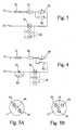
- FIG. 3 represents the diagram of an electrical power supply control circuit in a lamp according to the present invention.
- a resistor R1 of suitable value to limit the maximum current circulating in the lamp, is connected in series downstream of the protective fuse 23.
- the circuit Downstream of the resistor R1, the circuit continues with parallel connection between the PTC thermistor 40 and a resistor R2 with suitable value to correct the current of this thermistor 40. At the output of the parallel connection of these two components, the circuit continues with one or more LEDs 30 connected in parallel with one another and then continues to the other terminal 22 of the lamp.
- FIG. 4 An alternative embodiment to the circuit of Figure 3 is represented in Figure 4 , in which, between the LEDs 30 and the terminal 22, a capacitor C1 as current limiter and a respective discharge resistor R3 are also provided, connected in parallel to each other.
- This embodiment of the circuit is more suitable in the case in which low power LEDs 30 are used.
- the limiting resistor R1 must dissipate a large amount of energy and it is therefore advisable to fit a capacitor C1 in series with the circuit to vary the phase of the current and decrease leakages.
- Figures 5A and 5B show some possible embodiments of a lamp according to the invention with two or three LEDs 30.
- the lamp in the configuration of Figure 5A provides for the use of two LEDs 30 and the PTC thermistor is composed of an SMD component mounted on the opposite face of the board 11 with respect to the LEDs 30.
- the lamp in the configuration of Figure 5B includes, for example, three LEDs 30 and a PTC thermistor mounted on the same face of the board 11 housing the LEDs.
- the PTC thermistor is not of the SMD type, as in the case represented in Figure 5B , it must in any case be thermally coupled to the surface of the board, for example using also in this case thermally conductive pastes such as those previously described for thermal coupling between the body made of plastic material 10 and the dissipator 50.
- a lamp according to the present invention does not produce electromagnetic emissions.
- the lamp can also be produced with a different base with respect to the screw base and can also comprise a different number of LEDs, if necessary also with different colours and/or emission temperatures to one another.
- the supporting board 11 for the LEDs 30 and the board with the relative printed conductive tracks for supporting the components of the power supply control circuit can also be distinct from each other, provided that the contact is maintained between the thermistor 40 and the board 11, or at least a certain closeness sufficient to ensure the proper thermodynamic coupling between the PTC thermistor 40 and the heat dissipator 50.
- the body 10 made of thermally conductive plastic material can also be moulded directly on the aluminium dissipator 50.
Landscapes
- Engineering & Computer Science (AREA)
- General Engineering & Computer Science (AREA)
- Physics & Mathematics (AREA)
- Microelectronics & Electronic Packaging (AREA)
- Optics & Photonics (AREA)
- Circuit Arrangement For Electric Light Sources In General (AREA)
Priority Applications (1)
| Application Number | Priority Date | Filing Date | Title |
|---|---|---|---|
| EP09009400A EP2150093A3 (de) | 2008-07-30 | 2009-07-20 | LED-Lampe und Betriebsverfahren dafür |
Applications Claiming Priority (2)
| Application Number | Priority Date | Filing Date | Title |
|---|---|---|---|
| EP08425529 | 2008-07-30 | ||
| EP09009400A EP2150093A3 (de) | 2008-07-30 | 2009-07-20 | LED-Lampe und Betriebsverfahren dafür |
Publications (2)
| Publication Number | Publication Date |
|---|---|
| EP2150093A2 true EP2150093A2 (de) | 2010-02-03 |
| EP2150093A3 EP2150093A3 (de) | 2012-04-18 |
Family
ID=39865554
Family Applications (1)
| Application Number | Title | Priority Date | Filing Date |
|---|---|---|---|
| EP09009400A Withdrawn EP2150093A3 (de) | 2008-07-30 | 2009-07-20 | LED-Lampe und Betriebsverfahren dafür |
Country Status (1)
| Country | Link |
|---|---|
| EP (1) | EP2150093A3 (de) |
Cited By (4)
| Publication number | Priority date | Publication date | Assignee | Title |
|---|---|---|---|---|
| DE102011114253A1 (de) * | 2011-09-26 | 2013-03-28 | e:lumix OptoSemi Industries Verwaltungs GmbH | Leuchtvorrichtung |
| CN103162259A (zh) * | 2013-03-01 | 2013-06-19 | 河南华阳光电照明技术有限公司 | 一种led灯具通过安规高压测试的方法及一种高耐压led灯具 |
| CN104244501A (zh) * | 2013-06-14 | 2014-12-24 | 海洋王(东莞)照明科技有限公司 | 一种具有主动散热装置的灯具 |
| US20150062939A1 (en) * | 2012-02-28 | 2015-03-05 | Peter Frieden | Bicycle dynamo |
Citations (2)
| Publication number | Priority date | Publication date | Assignee | Title |
|---|---|---|---|---|
| EP0891120A2 (de) | 1997-07-07 | 1999-01-13 | Reitter & Schefenacker GmbH & Co. KG | Schaltungseinrichtung zum Schutz von strombetriebenen Leuchtmittein, insbesondere von LEDs, zu Signal- oder Beleuchtungszwecken |
| EP1526759A2 (de) | 2003-10-16 | 2005-04-27 | Immobiliare Eder S.R.L. | Steuerungsgerät für Leuchtdioden |
Family Cites Families (1)
| Publication number | Priority date | Publication date | Assignee | Title |
|---|---|---|---|---|
| TWI279659B (en) * | 2005-12-27 | 2007-04-21 | Polytronics Technology Corp | LED with temperature control function |
-
2009
- 2009-07-20 EP EP09009400A patent/EP2150093A3/de not_active Withdrawn
Patent Citations (2)
| Publication number | Priority date | Publication date | Assignee | Title |
|---|---|---|---|---|
| EP0891120A2 (de) | 1997-07-07 | 1999-01-13 | Reitter & Schefenacker GmbH & Co. KG | Schaltungseinrichtung zum Schutz von strombetriebenen Leuchtmittein, insbesondere von LEDs, zu Signal- oder Beleuchtungszwecken |
| EP1526759A2 (de) | 2003-10-16 | 2005-04-27 | Immobiliare Eder S.R.L. | Steuerungsgerät für Leuchtdioden |
Cited By (6)
| Publication number | Priority date | Publication date | Assignee | Title |
|---|---|---|---|---|
| DE102011114253A1 (de) * | 2011-09-26 | 2013-03-28 | e:lumix OptoSemi Industries Verwaltungs GmbH | Leuchtvorrichtung |
| US20150062939A1 (en) * | 2012-02-28 | 2015-03-05 | Peter Frieden | Bicycle dynamo |
| US9463835B2 (en) * | 2012-02-28 | 2016-10-11 | Velogical Engineering Gmbh | Bicycle dynamo |
| CN103162259A (zh) * | 2013-03-01 | 2013-06-19 | 河南华阳光电照明技术有限公司 | 一种led灯具通过安规高压测试的方法及一种高耐压led灯具 |
| CN104244501A (zh) * | 2013-06-14 | 2014-12-24 | 海洋王(东莞)照明科技有限公司 | 一种具有主动散热装置的灯具 |
| CN104244501B (zh) * | 2013-06-14 | 2016-10-12 | 海洋王(东莞)照明科技有限公司 | 一种具有主动散热装置的灯具 |
Also Published As
| Publication number | Publication date |
|---|---|
| EP2150093A3 (de) | 2012-04-18 |
Similar Documents
| Publication | Publication Date | Title |
|---|---|---|
| US9301362B2 (en) | LED driver circuit | |
| EP2718616B1 (de) | Festkörperbeleuchtungsvorrichtung unter verwendung von wärmekanälen in einem gehäuse | |
| EP2227925B1 (de) | Austausch einer led-leuchte in einer niedrigleistungsglühlampe | |
| US11877362B2 (en) | Light emitting diode thermal foldback control device and method | |
| US8444299B2 (en) | Dimmable LED bulb with heatsink having perforated ridges | |
| US9293447B2 (en) | LED thermal protection structures | |
| WO2009035203A1 (en) | Led lighting of fluorescent lamp with ballaster | |
| JP5398249B2 (ja) | 電源装置及び照明装置 | |
| US20130241426A1 (en) | Led light comprising an integrated driver | |
| US8004216B2 (en) | Variable intensity LED illumination system | |
| JP2006012622A (ja) | Led点灯装置、led実装基板およびledパッケージ | |
| JP5410906B2 (ja) | 照明装置 | |
| EP2150093A2 (de) | LED-Lampe und Betriebsverfahren dafür | |
| US20140042908A1 (en) | Connector with Surge Protection Structure | |
| US20160334091A1 (en) | Led lighting apparatus | |
| JP2025171999A (ja) | 多機能保護回路を備えた照明装置 | |
| KR20180120394A (ko) | 우회 전력 소모 수단을 이용한 과전압 보호 장치 | |
| US20120081004A1 (en) | Light emitting diode system | |
| US9194569B2 (en) | Illuminant device with over-temperature protecting function | |
| Kamal et al. | Fabrication of LED flood light from recycle material with high quality | |
| JPH11167425A (ja) | 定電流モジュール | |
| KR200164587Y1 (ko) | 취침등 | |
| CN204362401U (zh) | Led过温保护电路 | |
| CN115700001A (zh) | 用于设置灯具的驱动电流的方法和系统 | |
| Tang et al. | A Design of Ring-Shaped LED Driving Circuit Used in Optical Instruments Illuminating System |
Legal Events
| Date | Code | Title | Description |
|---|---|---|---|
| PUAI | Public reference made under article 153(3) epc to a published international application that has entered the european phase |
Free format text: ORIGINAL CODE: 0009012 |
|
| AK | Designated contracting states |
Kind code of ref document: A2 Designated state(s): AT BE BG CH CY CZ DE DK EE ES FI FR GB GR HR HU IE IS IT LI LT LU LV MC MK MT NL NO PL PT RO SE SI SK SM TR |
|
| AX | Request for extension of the european patent |
Extension state: AL BA RS |
|
| PUAL | Search report despatched |
Free format text: ORIGINAL CODE: 0009013 |
|
| AK | Designated contracting states |
Kind code of ref document: A3 Designated state(s): AT BE BG CH CY CZ DE DK EE ES FI FR GB GR HR HU IE IS IT LI LT LU LV MC MK MT NL NO PL PT RO SE SI SK SM TR |
|
| AX | Request for extension of the european patent |
Extension state: AL BA RS |
|
| RIC1 | Information provided on ipc code assigned before grant |
Ipc: H05B 33/08 20060101AFI20120312BHEP |
|
| STAA | Information on the status of an ep patent application or granted ep patent |
Free format text: STATUS: THE APPLICATION IS DEEMED TO BE WITHDRAWN |
|
| 18D | Application deemed to be withdrawn |
Effective date: 20120201 |